
MSC – Motor and Suspension Check#
MSC - Tutorial#
Overview#
The Motor and Suspension Check (MSC) is an add-on to the KLIPPEL Analyzer System for the QC end-of-line testing framework. This module measures selected large signal parameters such as voice coil offset and suspension asymmetry within an extremely short measurement time. The parameters are easy to interpret and give feedback for process control to avoid manufacturing units which will fail the test specification. The MSC can be applied to all kinds of transducers such as woofers, tweeters, headphones, micro-speakers and compression drivers, even mounted in a closed or vented box.
What is the Goal of This Tutorial?#
This tutorial makes you familiar with the MSC module. It is divided into the following steps:
Creating an MSC Test#
QC System Framework#
Creating a New QC Test#
Open the
Click
Give the test a clear name and choose a proper Transducer test template (i.e. Woofer), then click Ok.
You may log into the test now by clicking on the Measure button.
Note
You may select template Woofer with Coil Offset. This template already includes MSC.
Adding the MSC Task#
Follow these steps to add a new MSC task to your existing test sequence.
Skip this step if you have selected a test template that already includes MSC.
Start the QC Test; click the Add… button in the Tasks section of the property page to add a new task.
Choose the task script msc.task.klb. The default location is
%ProgramData%\Klippel\QC\Scripts\Klippel\QC\Modules
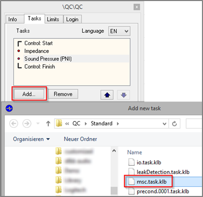
The MSC task will be added to the list of measurement tasks.
Note
Adding a new task always requires creating new reference units. You have to confirm that you want to delete all reference measurements, if limits exist in your test.
It is recommended to put the MSC at the first position in the tasks sequence to speed-up the complete test. While the MSC processes the data, the following tasks can start measurement.
Note
The acoustical decay of the MSC large signal test may degrade acoustical tests results (e.g. Rub&Buzz) of the following step. Therefore, Sound Pressure task should not be located after MSC, especially if the measurement is performed in a reverberant environment.
R&D System Framework#
If you are operating the MSC in the KLIPPEL R&D System framework, you may add a QC MSC operation by using the provided operation template.
Create or open a KLIPPEL database
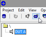
Add a new operation by using the operation icon or
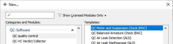
Select Module - QC quality control and Template – QC Motor and Suspension Check (MSC)); you may enter MSC in the filter input field to quickly find the template
Choose a name and click OK to create a new QC operation
Click Run
 to log in.
See dB-Lab Software Manual for more information.
Performing a First MSC Test#
This is a step-by-step guide about how to perform a first MSC measurement.
Setting up the Hardware#
Running the MSC task requires a KLIPPEL Analyzer device (Production Analyzer or KLIPPEL Analyzer 3) and an external or internal power amplifier (KA3 QC-Card or Amplifier-Card). No microphone is required for the MSC.
Find more general information about setting up the hardware setup in QC User Manual.
Note
Using QC Stand-alone Software the BAC can also be operated with 3rd party test front-ends such as smart amplifier (e.g. Powersoft Mezzo) that provide a WDM Audio or ASIO driver (natively or via virtual sound cards). However, optimal testing with BAC can only be ensured using a KLIPPEL Analyzer with dedicated and highly sensitive voltage and current sensing. Please refer to QC Manual section Using Soundcards and Testing Digital Audio Devices for more information.
Your First MSC Test#
After adding the new MSC task to your test sequence, you can start with your first measurement. In QC Engineer mode you may select the MSC task and edit the setup parameters. Refer to the next section for more information about the most important parameters.
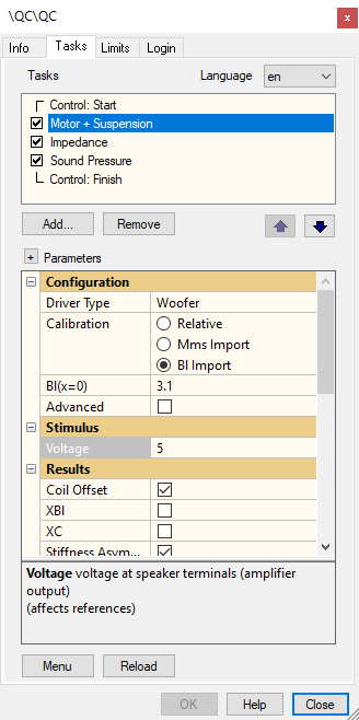
Select the correct Driver Type according to your test unit and check the voltage setting before running the MSC.
Click on the Start button to start your first measurement
Basic Settings#
These are the basic settings that have to be adjusted according to the connect test object. For detailed considerations about finding suitable test settings based on results of the KLIPPEL R&D System, refer to Application Note 65 Linking Large Signal Testing Between QC and R&D .
Driver Type#
In this menu you have to select one of the listed driver templates. Choose the Driver Type that fits best to your device under test (DUT) according to its typical resonance frequency. Please find more information in section Finding the Optimal Driver Type.
Note
Tweeters with a lower resonance frequency may be handled as micro speakers and in the same way micro speakers with a very low resonance may be handled as midrange drivers.
Voltage#
Here, the RMS voltage of the stimulus signal is specified. It should be set high enough to drive the speaker in the large signal range to get sensible results for the nonlinear parameters.
The stimulus signal contains very high peak voltage, about 3 to 4 times higher than the RMS voltage. Please use a powerful amplifier that can provide enough peak voltage without clipping.
Warning
A too high voltage can damage your speakers! Check peak displacement in the result table to make sure that the safe range is not exceeded. A suitable target peak displacement may be taken from LSI measurements with the KLIPPEL R&D System. Please find more information in AN 65 Linking Large Signal Testing Between QC and R&D.
Calibration (Relative, Mms Import, Bl Import)#
The MSC is based on voltage and current measurement only. A laser sensor is not required for nonlinear parameter identification. However, a mechanical calibration factor is required to get result parameters in absolute units.
If you choose Relative measurement, no mechanical T/S parameters (e.g. \(K_{\text{ms}}\)) are displayed and the values of coil offset and the mechanical state variables (e.g. displacement) are expressed in percent (the coil displacement is given relative to \(x_{\text{peak}}\), the peak displacement during the measurement).
By importing a typical \(Bl(x = 0)\) or \(M_{\text{ms}}\) instead, all mechanical measures are displayed in absolute units (e.g., displacement in mm).
Viewing MSC Results#
In this section the most important results of the MSC are explained.
Summary Window#
The Summary window shows the results measured by the MSC task.
The most important results are:
Coil Offset \(x_{\text{off}}\)
Stiffness Asymmetry \(A_{\text{kms}}\)
\(X_{Bl}\) and \(Bl_{\text{min}}\)
\(X_{C}\) and \(C_{\text{ms,min}}\)
\(X_{\text{peak}}\)
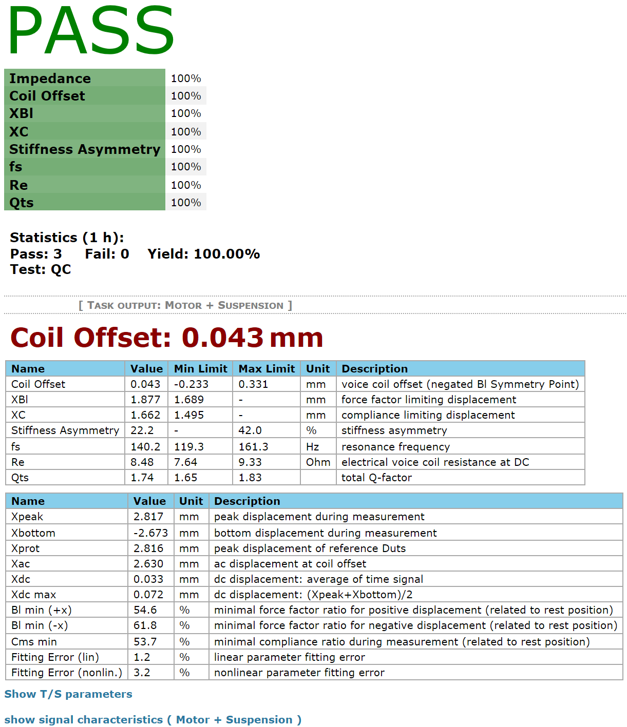
The table below gives a short explanation of the single-valued parameters measured by MSC. Please find a detailed definition in the MSC – Reference which also explains the relationship to the nonlinear curve parameters measured by other techniques (Large Signal Identification of KLIPPEL R&D System).
- Coil Offset
Voice Coil Offset is a useful characteristic to evaluate the rest position of the voice coil based on nonlinear force factor \(Bl(x)\) characteristic. A coil offset may generate 2nd-order harmonic distortion, a DC component in the displacement, initiate a motor instability or it limit the excursion range. MSC provides two calculation modes for the Coil Offset: Bl Symmetry Point and relative to Reference DUT.
\(Bl(x)\) symmetry point based method is useful for assessing the asymmetry of the motor which can be compensated by a voice coil shift (see Method 1: Bl Symmetry Point).
The alternative calculation method relative to Reference DUT is suitable for asymmetric motor topologies, where the coil offset is defined relative to an approved reference unit (see Method 2: Reference DUT).
Note
By default, the voice coil offset is defined as a shift recommendation, which is the actual offset with inverted sign. Therefore, the stated value must be applied to compensate the actual offset. This can be switched using the parameter Coil Offset Sign.
- Stiffness Asymmetry
The stiffness asymmetry \(A_{\text{kms}}\) is a useful characteristic for assessing the large signal asymmetry of the suspension part which generates 2nd-order harmonic distortion. Stiffness asymmetry only considers asymmetrical variation of the suspension nonlinearity separated from other nonlinearities. \(A_{\text{kms}}\) should be close to zero. The sign corresponds to the sign of the DC displacement generated by an asymmetrical suspension.
- \(X_{\text{peak}}\) , \(X_{\text{bottom}}\) , \(X_{\text{ac}}\) , \(X_{\text{dc}}\) and \(X_{\text{dc,max}}\)
The \(X_{\text{peak}}\) and \(X_{\text{bottom}}\) parameters represent the maximum and respectively minimum voice coil excursion during measurement. If no mechanical calibration was entered, the larger of the two displacements defines the reference of 100 %.
The \(X_{\text{ac}}\) parameter provides the (virtual) AC displacement around the Bl Symmetry Point. \(X_{\text{dc}}\) represents the true DC of the displacement time signal (mean value), while \(X_{\text{dc,max}}\) is based on \(X_{\text{peak}}\) and \(X_{\text{bottom}}\) only.
Note
older versions of the MSC only provided \(X_{\text{peak}}\) which represents the maximal absolute displacement (positive or negative).
- \(X_{Bl}\) and \(Bl_{\text{min}}\)
The force factor limited displacement \(X_{Bl}\) is a useful characteristic for finding a motor defect causing significant harmonic distortion.
However, harmonic distortion is not a unique symptom but may be caused by other nonlinearities. \(X_{Bl}\) considers symmetrical and asymmetrical variation of the force factor only.
Note
Any voice coil offset directly degrades/affects \(X_{Bl}\) as well.
\(Bl_{\text{min}}\) represents the minimal force factor ratio. It describes the maximal variation of the force factor during the measurement relative to the rest position in percent \(\bigl( \frac{\triangle Bl}{BL(x = 0)} \bigl)\). Both \(Bl_{\text{min}}\) for positive (\(+x\)) and negative (\(-x\)) displacements is given by the MSC.
- \(X_{C}\) and \(C_{\text{ms,min}}\)
The compliance limited displacement \(X_{C}\) is a useful characteristic for finding a defective suspension part such as a spider or surround causing significant harmonic distortion (THD). However, harmonic distortion is not a unique symptom of suspension problems but may also be caused by a voice coil offset. \(X_{C}\) considers symmetrical and asymmetrical variation of the suspension nonlinearity only.
The \(C_{\text{ms}}\) variation represents the minimal compliance ratio. It describes the maximal variation of the compliance during the measurement relative to the rest position in percent \(\bigl( \frac{\triangle C_{\text{ms}}}{C_{\text{ms}}(x = 0)} \bigl)\).
Impedance#
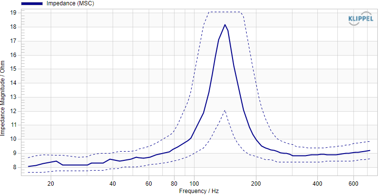
The MSC task also measures the impedance magnitude, which can be found in result window Impedance. If the impedance measure is activated, limits may be defined for the impedance curve.
Note
The impedance curve is a result of a large signal measurement. Therefore, a distorted curve is typical and expected. The curve distortion should be reproducible because it is caused by the speaker’s inherent nonlinearities.
T/S Parameters#
The MSC task may measure the following effective linear Thiele/Small parameters measured in the large signal domain. Limits may be applied to them:
- Voice coil resistance
- \(R_{\text{e}}\) in Ohm
- Resonance frequency
- \(f_{\text{s}}\) in Hz
- Total loss factor
- \(Q_{\text{ts}}\)
- Vented enclosure resonance frequency )
- \(f_{\text{b}}\) in Hz
only for Driver Type - … in vented box
- Vented enclosure loss factor
- \(Q_{\text{b}}\)
only for Driver Type - … in vented box
These additional Thiele/Small parameters can be found in the Summary Window, but no limits can be applied:
- Electrical loss factor
- \(Q_{\text{es}}\)
- Mechanical loss factor
- \(Q_{\text{ms}}\)
- Inductance of the LR2 Model
- \(L_{\text{e}}\) in mH
- Electrical capacitance representing moving mass
- \(C_{\text{mes}}\) in \(\mu \text{F}\)
- Electrical inductance representing driver compliance
- \(L_{\text{ces}}\) in mH
- Electrical resistance representing mechanical losses
- \(R_{\text{es}}\) in Ohm
These parameters are only available when the results are mechanically calibrated by a specified \(Bl(x = 0)\) or Mms:
- Force Factor
- \(Bl\) in N/A
- Moving mass
- \(M_{\text{ms}}\) in g
- Stiffness
- \(K_{\text{ms}}\) in N/mm
- Mechanical resistance
- \(R_{\text{ms}}\) in kg/s
Testing with Limits#
Limits can be defined for the following measures:
- Coil Offset
relative, statistic, absolute, shift
- \(X_{Bl}\)
relative, statistic, absolute
- \(X_{C}\)
relative, statistic, absolute
- Stiffness Asymmetry
shift, statistic, absolute
- \(f_{\text{s}}\)
relative, statistic, absolute
- \(R_{\text{e}}\)
relative, statistic, absolute
- \(Q_{\text{ts}}\)
relative, statistic, absolute
- \(f_{\text{b}}\)
relative, statistic, absolute
- \(Q_{\text{b}}\)
relative, statistic, absolute
These limit calculation modes can be selected:
- Relative
Tolerance is the percentage the measured parameter may differ in positive or negative direction in relation to the average value of the reference units
Note
The reference value for the relative limit of the Coil Offset, \(X_{Bl}\) and \(X_{C}\) is \(X_{\text{prot}}\) which equals \(X_{\text{peak}}\) of the selected main MSC Reference DUT.
- Statistic
Sigma is the standard deviation factor for a uniform distribution of measurement values
Statistic limit calculation is only reasonable for a statistically significant amount of reference units.- Absolute
Defines absolute values for the lower (min) and the upper (max) limit.
This value is independent of the reference units- Shift
The shift value is added to the average value of the reference units for the upper limit and subtracted from the average value for the lower limit.
For additional information about limit calculation modes see QC Manual section Limit Calculation.
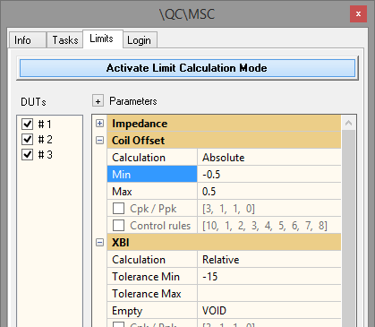
Production Capability and Process Performance indexes (\(C_{\text{pk}}\), \(P_{\text{pk}}\)) as well as Control rules can be activated for all single value measures (for details see QC User Manual section Ppk / Cpk).
Note
The MSC task uses calculation results from limit measurements (MSC Reference DUT) to speed up signal processing in testing mode. Therefore, processing is considerably quicker when measuring with at least one reference DUT existing.
Customizing the MSC Task#
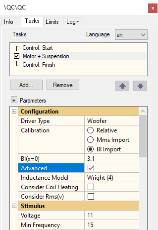
This section describes how to select optimal setup parameters for the MSC task. Some sections refer to advanced setup parameters that may be activated with the checkbox Advanced in the MSC properties as shown below.
For detailed considerations about finding suitable test settings based on results of the KLIPPEL R&D System, refer to Application Note 65 Linking Large Signal Testing Between QC and R&D.
Please refer to section Advanced Setup for more information.
Note
As long as the Advanced checkbox is deactivated, all advanced settings are set to default values according to the selected Driver Type. For most applications, the Driver Type settings templates provide optimal settings. Activate Advanced setup only if you are encountering errors or unreliable results.
Finding the Optimal Driver Type#
In order to obtain meaningful measurement results it is very important to choose the correct Driver Type template in your MSC task depending on the specified resonance frequency. Select the correct driver type according to this table:
Driver Type |
Resonance frequency \(f_{\text{s}}\) (Hz) |
|---|---|
Subwoofer |
\(f_{\text{s}}\) below 80 Hz |
Woofer |
40 Hz \(< f_{\text{s}} <\) 150 Hz |
Midrange Driver |
150 Hz \(< f_{\text{s}} <\) 400 Hz |
Microspeaker |
400 Hz \(< f_{\text{s}} <\) 1500 Hz |
Tweeter |
\(f_{\text{s}}\) above 1000 Hz |
The MSC can also be applied to drivers that are already mounted in a vented box system. In this case, the following Driver Types shall be selected:
Driver Type |
Resonance frequency \(f_{\text{s}}\) (Hz) |
|---|---|
Subwoofer in Vented \(>\) Box |
Box \(f_{\text{s}}\) below 80 Hz |
Woofer in Vented Box |
40 Hz \(< f_{\text{s}} <\) 150 Hz |
Midrange in Vented Box (This template applies for small full range systems.) |
150 Hz \(< f_{\text{s}} <\) 400 Hz |
Note
In case the resonance frequency of the tested speaker fulfills the frequency range of two different Driver Type templates, it is recommended to select the “lower” template. This may improve accuracy as a longer test time is used.
Setting the Stimulus Voltage#
The Voltage setting indirectly defines the peak displacement during the MSC measurement. Use a sufficiently high excitation voltage to drive the DUT in the large signal range. This is necessary to generate nonlinear distortion which is the basis for the identification of the nonlinear parameters.
The stimulus voltage should be adjusted in order to achieve a defined peak displacement, which is usually defined by thermal or mechanical protection limits. Ideally, the reference peak displacement is defined by measurement results of the Large Signal Identification (LSI) module of the KLIPPEL R&D System. Otherwise refer to the rated peak displacement or power handling limits according to the device’s specification.
The peak displacement achieved during the measurement is displayed in the MSC’s state parameter table (Summary window).
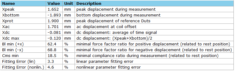
Since the target peak displacement is not always known and does not provide information about the “nonlinearity” of the operating range, a reasonable indicator is the \(Bl(x)\) decay achieved during the test, instead. The parameter \(Bl_{\text{min}}\) in percent expresses the decay of the force factor at positive and negative peak excursion related to coil rest position. A symmetric decay below 70 % is desirable (although not always possible).
Note
A \(Bl(x)\) decay below 30 % shall be avoided since limiting effects may degrade the results or may result in instabilities of the algorithm.
Getting Absolute Mechanical Parameters#
To measure the mechanical values in absolute units, it is required to calibrate the measurement.
As no mechanical sensors are used, this can be done by:
Inserting the value of \(Bl(x = 0)\) in
Inserting the value of the moving mass in
These parameters are measured accurately with the LPM – Linear Parameter Measurement of the KLIPPEL R&D System or the Impedance task (with TSX license) using a laser sensor. Alternatively, the Added Mass task as of the QC System may be used for this purpose.
In end-of-line testing, the mechanical calibration is usually not updated for each tested DUT. Therefore, a typical value shall be entered. It is recommended to use the parameter which is more stable in production.
Note
You have to enter the calibration before the measurement to get absolute results; otherwise, the measurement needs to be repeated.
Coil Offset Calculation Mode#
As stated in section Summary Window the Coil Offset may be calculated in two different ways. The Coil Offset Mode may be selected in parameter section Processing as shown below.
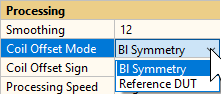
This section gives some information on selecting and using the right calculation mode. For details about the actual calculation methods please refer to section Voice Coil Offset Xoffset.
Note
The sign (interpretation) of the stated coil offset value may be switched with parameter Coil Offset Sign.
Bl Symmetry#
The default calculation mode is based on the symmetry characteristic of the nonlinear force factor (Bl(x) Symmetry Point) characteristic as defined in section Method 1: Bl Symmetry Point. This mode is preferable if the test object has a relatively symmetrical \(Bl(x)\) curve shape, which is only shifted due to a misplacement of voice coil rest position.
For most regular transducers with symmetric motor designs, this calculation mode is suitable. An absolute coil offset close to zero is usually desirable for optimal performance.
Note
You may test, whether this mode is suitable by measuring coil offset at different voltage settings. If the coil offset varies significantly with voltage/peak displacement, the force factor characteristic is most likely not symmetric. Consider selecting Reference DUT mode in this case.
Reference DUT#
This calculation mode uses a novel technique to estimate the coil offset of a device under test relative to a defined reference driver of the same type. The calculation is also based on the nonlinear force factor \(Bl(x)\) characteristic, but it requires a defined reference. See section Method 2: Reference DUT for an example and more information.
This mode may be applied to any electro-dynamic transducer, but it is especially recommended in case the force factor characteristic is asymmetrical by design due to motor topology (e.g. micro speaker). In this case \(Bl\) symmetry point based method is not valid. It is also suitable if the deviation to a defined reference unit is of interest.
After selecting mode Reference DUT in MSC properties, the coil offset is not measured until a reference unit has been assigned. In order to do so, activate Limit Calculation Mode and measure at least one reference DUT.
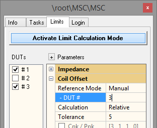
The relative coil offset is only defined for one specific reference unit, therefore one DUT must be picked out of the reference DUT pool in case there is more than one. Parameter Reference Mode defines how the DUT is assigned:
Auto - the DUT with the most average coil offset is selected automatically as reference
Manual – the MSC reference is defined manually by entering the DUT number
After pressing Calculate, the selected reference DUT is indicated in Summary window as shown below. In the limit table the coil offset of all reference units relative to the selected unit is displayed.

Note
The MSC Reference DUT provides further meta information which is used to speed up the processing in normal testing. Therefore, make sure you only select valid and representative units.
Finding the Optimal Test Time#
The total MSC test time depends on the duration of the Preloop (to generate steady state condition), the duration of the main measurement and the signal processing time. The processing may be performed while the next task (e.g. SPL task) is running.
Note
As soon as reference data and limits are existing, the calculation time of the MSC will be significantly faster. The result obtained from the MSC Reference DUT is used to speed-up signal processing. Refer to section Reference DUT for more information.
Main Measurement#
The default measurement time depending on Driver Type is listed in the following table.
Driver type |
Time in s (without preloop) |
|---|---|
Subwoofer |
2.73 |
Woofer |
1.35 |
Midrange |
0.68 |
Micro- speaker |
0.34 |
Tweeter |
0.17 |
A longer measurement time can yield more accurate results but increases the processing time. Making the measurement shorter as the recommended values may degrade the precision of the results, therefore this is not recommended.
Note
To verify that the selected measurement time is sufficient, it is recommended to compare MSC results with reference results obtained with the Large Signal Identification (LSI) module of the KLIPPEL R&D System. If this is not available or results differ, start with a longer measurement time (activate Advanced mode) to obtain reference results and decrease time setting until results start to deviate.
Preloop#
Before the measurement starts, a fraction (or multiples) of the excitation signal is played back in order to achieve steady-state conditions of the DC. If the loudspeaker has significant asymmetrical nonlinear parameters, a DC component in the voice coil displacement can be generated which may shift the operating point.
The duration of the Preloop signal is specified always relative to the main measurement. The default settings are:
Driver type |
Preloop |
Test time including preloop |
|---|---|---|
Subwoofer |
0.5 |
4 s |
Woofer |
0.5 |
2 s |
Midrange Driver |
1 |
1.35 s |
Microspeaker |
1 |
0.7 s |
Tweeter |
1 |
0.4 s |
Decreasing the default Preloop may degrade the steady-state condition which may result in additional linear spectral components at low frequencies which will be interpreted as nonlinear distortion.
Note
Avoid a Preloop smaller than 0.5!
Tweeters which have significant stiffness asymmetries or ferro-fluids in the gap may need an extended preloop time to achieve steady-state condition. During the measurement a DC displacement may be generated which moves the coil away from the rest position. The visco-elastic behavior of the ferro-fluid can lead to a time constant of about 1 s and more.
Using the Optimal Inductance Model#
The Inductance Model is an advanced setup parameter of the MSC. The default setting depends on selected Driver Type.
The LR-2 model uses three parameters \(L_{\text{e}}\) , \(R_{\text{e}}\) , \(R_{2}\). The Leach model is the simplest model and uses only two parameters \(K\) and \(n\). It is recommended for micro speakers.
The most complex Wright model uses four parameters. Increasing the complexity of the model will require more bandwidth of the stimulus. This is the default model for low frequency transducers.
Note
The inductance model which is most suitable for your speaker may be identified using the Linear Parameter Measurement (LPM) module of the KLIPPEL R&D System.
Use a higher value for \(f_{\text{stop}}\) if the inductance model cannot be identified. In this case the linear error is too high, a warning will be displayed.
Note
A poor linear fitting due to wrong selection of inductance model also impairs the nonlinear model fitting and thus the MSC result.
Optimal Frequency Range#
For the proper identification of the linear and nonlinear transducer parameters, a persistent excitation with sufficient bandwidth is necessary. The main bandwidth of the excitation spectrum is adjusted by the advanced parameters Min. Frequency (\(f_{\text{min}}\)) and Max. Frequency (\(f_{\text{max}}\)). Moreover, F Re (\(f_{R_{\text{e}}}\)) defines the frequency of an additional low frequency tone for measuring \(R_{\text{e}}\) (pilot tone).
The default settings according to the Driver Type templates are listed below:
Driver Type |
Min. Freq in Hz |
Max. Freq. in Hz |
F Re in Hz |
|---|---|---|---|
Subwoofer |
10 |
750 |
2 |
Woofer |
15 |
750 |
5 |
Midrange Driver |
50 |
1500 |
10 |
Microspeaker |
100 |
3000 |
10 |
Tweeter |
250 |
6000 |
10 |
Note
\(f_{\text{Re}}\) should be at least \(\frac{1}{10}\) of the resonance frequency \(f_{\text{s}}\) for proper identification of \(R_{\text{e}}\).
Acoustical Requirements#
The mechanical and acoustical system should be a 2nd order system that can be realized by measuring the loudspeaker in free air or mounted in a closed box. Ambient noise and the acoustical properties of the environment (room) are not critical for MSC.
Drivers mounted in vented box systems (4th order system) can also be measured (choose a Driver Type with vented box). The driver parameters are separated from the vented box parameters.
Note
The MSC cannot handle parasitic resonances such as acoustical resonance occurring in some horn compression drivers.
Powered Speaker Systems#
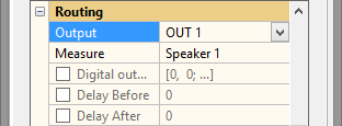
To be able to test powered systems with integrated amplifiers, the Routing parameter section of the MSC task must be activated. This can be done by selecting controlled by task in the Routing section of the Control: Start task.
The settings OUT1, OUT2 can be used to test active systems or systems, which do not require an external amplifier.
Warning
The test voltage is specified at the line level outputs! Amplifier gain is not checked.
For the measurement it is still necessary to connect the DUT to the Speaker outputs terminals, directly. The amplifier output must be fed through the analyzer hardware using the Amplifier input for input current and voltage measurement.
MSC – Reference#
Definition of Motor Parameters#
The motor parameters describe characteristics which are related to the force factor varying with voice coil displacement \(Bl(x)\). All parameters follow the definitions of the standard IEC 62458.
Bl-limited Peak Displacement XBl#
Definition#
The decrease of the force factor \(Bl(x)\) caused by coil displacement away from the rest position \(x = 0\) limits the maximal peak displacement. The force factor limited displacement \(X_{Bl}\) indicates the maximal displacement amplitude limited by motor distortion. It is indirectly defined by the ratio of the minimal force factor in the working range \(\pm X_{\text{Bl}}\) referred to the \(Bl\) value at the rest position
It shall be stated along with a defined minimal force factor ratio (typically: \(\text{Bl}_{\text{min}} = 82\: \%\)).
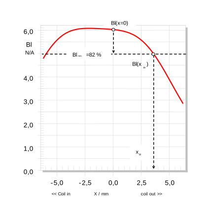
The definition is illustrated in Figure 1 showing a \(Bl(x)\)-curve measured by the Large Signal Identification (LSI) module of the KLIPPEL R&D system (curve not available in MSC):
Read the value \(Bl(x = 0)\) at the rest position and multiply this value with the threshold of the minimal force factor ratio (\(Bl_{\text{min}} = 82 \: \%\)).
Search for the smallest \(X_{Bl}\) where the \(Bl(x)\) equals \(Bl(x = 0) \cdot 0.82\).
The peak value \(X_{Bl}\) shall be reported with the used minimal force factor ratio, \(Bl_{\text{min}}\) for example: \(X_{Bl} = 3 \: \text{mm}\) (@ \(Bl_{\text{min}} = 82 \: \%\))
Application to end-of-line-testing#
The force factor limited displacement \(X_{Bl}\) is a useful characteristic for finding a motor defect causing significant harmonic distortion. However, harmonic distortion is not a unique symptom but may be caused by other nonlinearities. \(X_{Bl}\) considers symmetrical and asymmetrical variation of the force factor only. Minimal or maximal QC limits may be applied to check \(X_{Bl}\) and to make a PASS/FAIL decision.
Bl Symmetry Point XSYM#
Definition#
The Bl Symmetry Point describes the center point between two points on the \(Bl(x)\)-curve providing the same \(Bl\)-value
The distance between these points is 2 \(x_{\text{ac}}\) which is peak-to-peak value of a symmetric AC displacement.
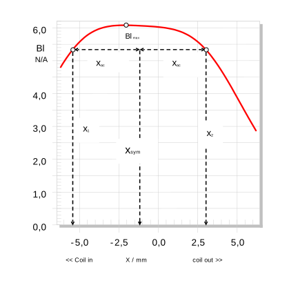
The definition is illustrated in Figure 2 showing a \(Bl(x)\)-curve measured by the Large Signal Identification (LSI) module of the KLIPPEL R&D system (curve not available in MSC):
Select a \(Bl\)-value that is smaller than or equal to \(Bl_{\text{max}}\) as illustrated in Figure 2
Read the corresponding displacement values \(x_{1}\) and \(x_{2}\) on both sides of the \(Bl\) maximum giving \(Bl(x_{1}) = Bl(x_{2})\).
Calculate the symmetry point \(X_{\text{sym}} = \frac{(x_{1} + x_{2})}{2}\) and the displacement \(X_{\text{ac}} = \frac{\vert x_{2} - x_{1} \vert}{2}\). Repeat the procedure for other \(Bl\)-values.
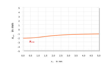
Plot the dependency of the symmetry point \(x_{\text{xym}}(x_{\text{ac}})\) versus displacement \(x_{\text{ac}}\) as a curve (Figure 3)
Application to end-of-line testing#
The symmetry point assesses the degree of symmetry of the \(Bl(x)\) curve depending on peak displacement. Thus, it is one base method for assessing the voice coil offset being a more useful characteristic for QC tests.
Voice Coil Offset Xoffset#
Method 1: Bl Symmetry Point#
Definition#
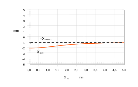
The voice coil offset \(X_{\text{offset}}\) is defined as the negative symmetry point \(x_{\text{sym}}(x_{\text{ac}})\) for a high value of \(x_{\text{ac}}(> x_{Bl})\)
It assesses the symmetry of \(Bl(x)\) at the steep slopes of the curve where field asymmetry has a lower impact to estimate a coil offset.
Note
The sign and thus the interpretation of the stated Coil Offset may be adjusted by parameter Coil Offset Sign, the default state is Shift recommendation which inverts the sign of the definition above. Therefore, it represents the shift recommendation to compensate the voice coil offset relative to the magnetic field. In MSC the maximal measured symmetric excursion defines the stated \(x_{\text{ac}}\).
The definition is illustrated in Figure 4 showing the symmetry point measured by the Large Signal Identification (LSI) module of the KLIPPEL R&D system (curve not available in MSC):
Calculate the symmetry point \(x_{\text{sym}}(x_{\text{ac}})\) as a function of displacement \(x_{\text{ac}}\).
Read the (negative) voice coil offset at max available displacement \(x_{\text{ac}}\).
Report the voice coil offset \(X_{\text{offset}}\) together with the amplitude \(x_{\text{ac}}\) for example: \(X_{\text{offset}} = 1.2 \: \text{mm}\) (@ \(X_{\text{ac}} = 5.0 \: \text{mm}\))
Application to end-of-line testing#
Voice coil offset is a useful characteristic for assessing the asymmetry of the motor which can be compensated by a voice coil shift. A coil offset generates 2nd-order harmonic distortion, a DC part in the displacement and may initiate motor instability. Therefore, \(x_{\text{offset}}\) should be close to zero.
Note
If the symmetry point varies significantly with \(x_{\text{ac}}\) (\(x_{\text{sym}}(x_{\text{ac}}) \neq\) constant), the asymmetry of the \(Bl\)-curve is caused by the asymmetry of the magnetic field which cannot be compensated by a coil shift completely. In this case use coil offset calculation Method 2: Reference DUT.
Method 2: Reference DUT#
Definition#
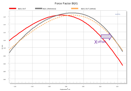
The voice coil offset \(x_{\text{offset}}\) is defined as the voice coil shift which must be applied to the DUT in order to achieve minimal deviation between \(Bl_{\text{DUT}}(x)\) and reference \(Bl_{\text{ref}}(x)\) curve of an approved DUT of the same type. \(x_{\text{offset}}\) results in minimizing the mean square error based on the sampled \(Bl(x)\) curves.
The curves are normalized first and weighting is applied to focus on the displacement range close to the rest position.
Note
The sign and thus the interpretation of the stated Coil Offset may be adjusted by parameter Coil Offset Sign, the default state is Shift recommendation according to the definition above. This means shift recommendation to compensate the voice coil offset relative to the reference DUT. By selecting offset it represents the actual voice coil offset relative to the reference DUT.
The following plot illustrates how \(Bl_{\text{DUT}}(x)\) (red curve) must be shifted in order to match the reference curve (grey) optimally resulting in the orange curve which is virtually shifted.
Application to end-of-line testing#
The relative coil offset is suitable for devices where the \(Bl\) symmetry point according to Method 1: Bl Symmetry Point cannot be applied. This mainly refers to drivers with asymmetric motor designs, such as micro speakers. The optimal coil rest position is often defined by geometrical restrictions rather than optimal force factor symmetry. By using an approved reference unit, which is close to the desired optimal coil rest position, relative coil offset can be calculated interpreted easily.
Note
Although there is no restriction for the curve shape of the nonlinear force factor, a local maximum (peak) is required in order to normalize the DUT and reference curves.
Definition of Suspension Parameters#
The suspension parameters describe characteristics which are related to the compliance \(C_{\text{MS}}(x)\) varying with voice coil displacement \(x\). All parameters follow the definitions of the standard IEC 62458.
CMS-limited Peak Displacement XC#
Definition#
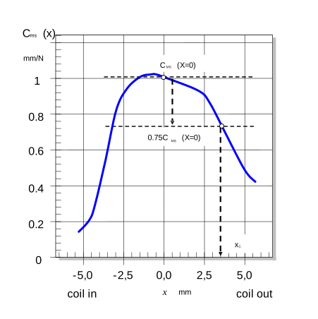
The decrease of the compliance value \(C_{\text{MS}}\) - caused by a displacement of the coil away from the rest position \(x = 0\) limits the maximal peak displacement. This value called compliance limited peak displacement \(X_{C}\) is implicitly defined by the condition that the minimal compliance ratio equals a threshold \(C_{\text{min}}\) (typically 75 %).
The definition is illustrated in Figure 6 showing a \(C_{\text{MS}}(x)\)-curve measured by the Large Signal Identification (LSI) module of the KLIPPEL R&D system (curve not available in MSC):
Read the value \(C_{\text{ms}}(x = 0)\) at the rest position and multiply this value with the threshold of the minimal compliance ratio (e.g. \(C_{\text{min}} = 75 \: \%\)).
Find the smallest \(X_{C}\) where \(C_{\text{ms}}(x)\) equals \(C_{\text{MS}}(x = 0) \cdot C_{min}\).
Application to end-of-line testing#
The compliance limited displacement \(X_{C}\) is a useful characteristic for detecting defective suspension parts such as a spider or surround causing significant harmonic distortion (THD). \(X_{C}\) considers symmetrical and asymmetrical variation of the suspension nonlinearity only.
Stiffness Asymmetry AK#
Definition#
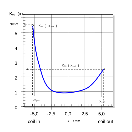
The asymmetry of the \(K_{\text{ms}}(x)\)-curve (inverted \(C_{\text{ms}}(x)\) curve) is the ratio defined by the stiffness at the maximal displacement achieved symmetrically during measurement.
The definition is illustrated in Figure 7 showing a \(K_{\text{MS}}(x)\)-curve measured by the Large Signal Identification (LSI) module of the KLIPPEL R&D system (curve not available in MSC):
Read the stiffness values at positive and negative peak displacement \(x_{\text{peak}}\) in the measured \(K_{\text{ms}}(x)\) curve as illustrated in
Calculate the stiffness asymmetry using the above-mentioned equation
Report the peak displacement \(x_{\text{peak}}\) together with the asymmetry value: \(A_{\text{K}} = 90 \: \%\) (\(x_{\text{peak}} = 5.5 \: \text{mm}\))
Note
It is recommended to calculate stiffness asymmetry for \(x_{\text{peak}} > x_{C}\).
Application to end-of-line testing#
The stiffness asymmetry \(A_{\text{K}}\) is a useful characteristic for assessing the asymmetry of the suspension part which typically generates 2nd-order harmonic distortion. This parameter only considers asymmetrical variation of the suspension nonlinearity. The stiffness asymmetry \(A_{\text{K}}\) should be close to zero. The sign of \(A_{\text{K}}\) corresponds to the sign of the DC displacement generated by an asymmetrical suspension.
Setup#
Template Based Setup#
The MSC offers several Driver Type templates for different standard transducers. Settings like measurement time, frequency range and resolution are set automatically and hidden in the user interface.
Find details about the standard parameters in the section Customizing the MSC Task.
Advanced Setup#
To customize all settings of the MSC, you may activate the advanced parameters by activating Advanced checkbox in the Configuration of the MSC task.
By default, these parameters are set automatically according to the selected Driver Type. In most cases the default settings are optimal. Please activate advanced parameters only if errors occur or the results are not reliable.
Note
If you activate the advanced parameters, the default values are normally filled in automatically. However, in some cases (e.g., right after changing Driver Type) this is not true. In any case, you can find the recommended values for the current driver type as comment below the Parameters panel.
Example:
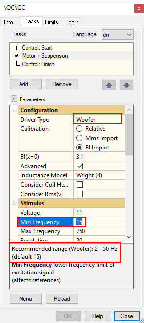
Driver Type Tweeter is selected. Hence for \(f_{\text{min}}\) the recommended range is shown in the parameter description (2 Hz … 50 Hz). Furthermore, the value (15 kHz) is given which is used for this type without advanced setup.
Stimulus#
For speeding up the measurements or to measure difficult speakers correctly it can be useful to modify some of the default settings.
- Min. Frequency
The frequency \(f_{\text{min}}\) is the lowest frequency in the main test signal band.
It should be at least 4 times lower than the resonance frequency of the driver.- Max. Frequency
The frequency \(f_{\text{max}}\) is the highest frequency in the excitation signal
It should be at least 3 times higher than the resonance frequency of the driver.Note
This parameter can affect result accuracy and overall test speed. Increasing \(f_{\text{max}}\) can lead to a longer processing time, but also more accurate results.
- F Re
This defines the lowest additional frequency in the excitation signal for \(R_{\text{e}}\) measurement (pilot tone)
It should be at least 10 times lower than the resonance frequency of the driver- Resolution
The resolution parameter gives the number of excited frequencies in the stimulus signal per octave.
The default value should not be changed.- Time
The parameter Time is the main measurement time in your MSC Task (without Preloop)
- Preloop
The parameter Preloop defines the additional excitation time spent to bring the speaker into steady state conditions. It is defined relative to the main test time (fraction/multiples)
A preloop of 1 means that the complete stimulus is played back once before the actual measurement starts.
The total time spent by MSC consists of the main test time \(+\) preloop time \(+\) processing time. Do not choose a preloop which is too short, it should be \(>\) 0.5 to achieve steady state conditions
If you get different results depending on the polarity of the driver connection (beside sign changes) then the preloop parameter needs to be increased.
- Compensate Amplifier
This parameter compensates the low frequency gain roll-off (high pass) of the amplifier. The compensation should only be activated in case of SNR problems.
Note
If your amplifier has not enough headroom deactivate this option or use a more powerful amplifier.
Processing#
Inductance Model#
In case the linear fitting error is high, you might try a different inductance model.
- Leach
The Leach model is the simplest model and uses only two parameters \(K\) and \(n\).
- LR-2
The LR-2 model uses three parameters \(L_{\text{e}}\) , \(R_{2}\) , \(R_{2}\).
- Wright
The Wright model is the most complex model, using four parameters. It may fall back to a simpler model automatically, however.
Note
Increasing the complexity of the model can require more bandwidth of the stimulus. Use a higher value of upper frequency limit in f the inductance model cannot be identified.
Nonlinear Mechanical Damping#
If enabled, the \(R_{\text{ms}}(v)\) nonlinearity is considered in the nonlinear driver model. See the LSI Manual of the KLIPPEL R&D system for more details.
This parameter mainly applies for small speakers such as headphone drivers and micro speakers. Hence it is enabled for the Driver Type Microspeaker only. It improves the fitting of the nonlinear model but has a minor influence on the coil offset result. It has minor influence on computation time.
Voice Coil Heating#
During longer measurements and small thermal capacities (micro speaker) the self-heating effect of the voice coil may affect the results. Using this option, the heating effect is compensated. However, the measurement time will be tripled.
Note
This option increases test and processing time significantly. It is recommended to use a longer pre-loop to establish steady state condition and a short measurement time instead.
Processing Speed#
Processing Speed controls the convergence speed of the nonlinear transducer parameter identification during on-line testing (with reference data & limits available). It is related to signal processing load only and does not affect the test signal duration.
The default mode ensures optimal result accuracy and stability. High speed mode speeds up calculation time in case a lower overall test cycle time is required. In most cases, this will not impair result accuracy. However, do not use this mode if fitting errors occur frequently during testing.
Note
Before QC version 6.4, Processing Speed was permanently set High. Therefore, you may use this mode for timing compatibility reasons. This parameter may be switched without discarding reference DUT’s and limits.
Reference DUT Integrity#
Most parameters may be adjusted without invalidating the limits and reference units. Menu option Preserve Reference DUT Integrity must be deactivated, though. For more information see section Reference DUT Integrity in QC User Manual.
Note
It is recommended to avoid significant setup deviation between reference units and online test. During operator testing, start values of the reference units are used to speed up calculation.
Settings Import#
Most task properties (setup and limit parameters) are available for import from an external parameter file during login.
Setup Parameters#
The following table lists the IDs of the parameters and the corresponding text labels (English version) as shown in the user interface. Only use the IDs for import.
- Driver Type
- Type: string
Note
can only be imported if no reference DUTs are available
Parameter Name (EN) |
ID (in parameter file) |
|---|---|
Driver Type |
|
|
|
|
|
|
|
|
|
|
|
|
|
|
|
|
|
- Calibration
- Type: string
Note
can only be imported if no reference DUTs are available
Parameter Name (EN) |
ID (in parameter file) |
|---|---|
Calibration |
|
|
|
|
|
|
|
- Mms
- Type: numerical value
Parameter Name (EN) |
ID (in parameter file) |
|---|---|
Mms |
|
- Bl(x=0)
- Type: numerical value
Parameter Name (EN) |
ID (in parameter file) |
|---|---|
Bl(x=0) |
|
- Advanced
- Type: bool
Note
can only be imported if no reference DUTs are available
Parameter Name (EN) |
ID (in parameter file) |
|---|---|
Advanced |
|
- Inductance Model
- Type: string
Note
can only be imported if no reference DUTs are available
Parameter Name (EN) |
ID (in parameter file) |
|---|---|
Inductance Model |
|
|
|
|
|
|
|
- Consider Coil Heating
- Type: bool
Parameter Name (EN) |
ID (in parameter file) |
|---|---|
Consider Coil Heating |
|
- Consider Rms(v)
- Type: bool
Parameter Name (EN) |
ID (in parameter file) |
|---|---|
Consider Rms(v) |
|
- Voltage
- Type: numerical value
Parameter Name (EN) |
ID (in parameter file) |
|---|---|
Voltage |
|
- Min. Frequency
- Type: numerical value
Parameter Name (EN) |
ID (in parameter file) |
|---|---|
Min. Frequency |
|
- Max. Frequency
- Type: numerical value
Parameter Name (EN) |
ID (in parameter file) |
|---|---|
Max. Frequency |
|
- Resolution
- Type: numerical value
Parameter Name (EN) |
ID (in parameter file) |
|---|---|
Resolution |
|
- Time
- Type: string
Parameter Name (EN) |
ID (in parameter file) |
|---|---|
Time |
|
|
|
|
|
|
|
|
|
|
|
|
|
- Preloop
- Type: numerical value
Parameter Name (EN) |
ID (in parameter file) |
|---|---|
Preloop |
|
- F Re
- Type: numerical value
Parameter Name (EN) |
ID (in parameter file) |
|---|---|
F Re |
|
- Compensate Amplifier
- Type: bool
Parameter Name (EN) |
ID (in parameter file) |
|---|---|
Compensate Amplifier |
|
- Custom File for Import
- Type: string
Parameter Name (EN) |
ID (in parameter file) |
|---|---|
Custom File for Import |
|
- Output (Routing)
- Type: string
Parameter Name (EN) |
ID (in parameter file) |
|---|---|
Output (Routing) |
|
|
|
|
|
|
|
|
|
|
|
- Measure
- Type: string
Parameter Name (EN) |
ID (in parameter file) |
|---|---|
Measure |
|
|
|
|
|
- Speaker 1 Connect
- Type: bool
Parameter Name (EN) |
ID (in parameter file) |
|---|---|
Speaker 1 Connect |
|
- Speaker 2 Connect
- Type: bool
Parameter Name (EN) |
ID (in parameter file) |
|---|---|
Speaker 2 Connect |
|
- Output Channel
- Type: integer vector
Parameter Name (EN) |
ID (in parameter file) |
|---|---|
Output Channel |
|
- Voltage Input Channel 1
- Type: numerical value
Parameter Name (EN) |
ID (in parameter file) |
|---|---|
Voltage Input Channel 1 |
|
- Current Input Channel 2
- Type: numerical value
Parameter Name (EN) |
ID (in parameter file) |
|---|---|
Current Input Channel 2 |
|
- Digital Output
- Type: numerical matrix
Parameter Name (EN) |
ID (in parameter file) |
|---|---|
Digital Output |
|
- Delay Before
- Type: numerical value
Parameter Name (EN) |
ID (in parameter file) |
|---|---|
Delay Before |
|
- Delay After
- Type: numerical value
Parameter Name (EN) |
ID (in parameter file) |
|---|---|
Delay After |
|
- Results
- Type: bool
Note
can only be imported if no reference DUTs are available
Parameter Name (EN) |
ID (in parameter file) |
|---|---|
|
|
|
|
|
|
|
|
|
|
|
|
|
|
|
|
|
|
|
|
- Smoothing
- Type: numerical value
Parameter Name (EN) |
ID (in parameter file) |
|---|---|
Smoothing |
|
- Coil Offset Mode
- Type: string
Note
can only be imported if no reference DUTs are available
Parameter Name (EN) |
ID (in parameter file) |
|---|---|
Coil Offset Mode |
|
|
|
|
|
- Coil Offset Sign
- Type: string
Note
can only be imported if no reference DUTs are available
Parameter Name (EN) |
ID (in parameter file) |
|---|---|
Coil Offset Sign |
|
|
|
|
|
- Processing Speed
- Type: string
Parameter Name (EN) |
ID (in parameter file) |
|---|---|
Processing Speed |
|
|
|
|
|
- Customizations
- Type: bool
Parameter Name (EN) |
ID (in parameter file) |
|---|---|
Customizations |
|
- Custom Parameter
- Type: String matrix
Parameter Name (EN) |
ID (in parameter file) |
|---|---|
Custom Parameter |
|
- Impedance - Ymax
- Type: numerical value
Parameter Name (EN) |
ID (in parameter file) |
|---|---|
Impedance - Ymax |
|
- Impedance - Ymin
- Type: numerical value
Parameter Name (EN) |
ID (in parameter file) |
|---|---|
Impedance - Ymin |
|
- Impedance – Scale
- Type: string
Parameter Name (EN) |
ID (in parameter file) |
|---|---|
Impedance – Scale |
|
|
|
|
|
- Custom Colors
- Type: bool
Parameter Name (EN) |
ID (in parameter file) |
|---|---|
Custom Colors |
|
- Impedance
- Type: numerical value
HTML color code (RGB integer); \(color = R + G ⋅ 256 + B ⋅ 65536\) with \(R,G,B = [0 ... 256]\)
Parameter Name (EN) |
ID (in parameter file) |
|---|---|
Impedance |
|
- Show MSC details
- Type: bool
Parameter Name (EN) |
ID (in parameter file) |
|---|---|
Show MSC details |
|
- Show T/S parameters
- Type: bool
Parameter Name (EN) |
ID (in parameter file) |
|---|---|
Show T/S parameters |
|
Note
For general information on importing task settings, see section Settings Import in QC User Manual.
Limits and Limit Settings#
All limit parameters of the task are available for import. The parameter IDs are a combination of the measure ID as the prefix and the parameter ID as suffix. The following tables list all measure and limit/parameter names (English version) and the corresponding IDs. Only use the IDs for import.
Note
For general information on limit import refer to QC User Manual section Limit Import.
Results (Prefix)#
Name |
ID |
|---|---|
Impedance |
|
Coil Offset |
|
XBl |
|
XC |
|
Stiffness Asymmetry |
|
fs |
|
Re |
|
Qts |
|
fb |
|
Qb |
|
Parameters (Suffix)#
Name |
ID |
|---|---|
Calculation (List items depend on measure) |
|
|
|
|
|
|
|
|
|
|
|
|
|
Min |
|
Max |
|
Shift (Mask) |
|
Shift Max (Only available for single value measures) |
|
Shift Min (Only available for single value measures) |
|
Tolerance (Mask) |
|
Tolerance Max (Only available for single value measures) |
|
Tolerance Min (Only available for single value measures) |
|
Sigma (Mask) |
|
Sigma Max (Only available for single value measures) |
|
Sigma Min (Only available for single value measures) |
|
Jitter (Only available for curve measures) |
|
Shift (Coil Offset) |
|
Tolerance (Coil Offset) |
|
Empty (Only available for measures Xc and XBl) |
|
|
|
|
|
|
|
Control Rules |
|
Cpk / Ppk (Only available for single value measures) |
|
Note
The parameter format differs between single value and curve measures. Please stick to the format as used in the user interface of Limit Calculation Mode.
Warnings and Error Messages#
Please contact support, if any other error or warning occurs except the following:
Specified voltage could not be realized#
The realized voltage may be less than the specified voltage due to finite output impedance of the power amplifier, cable losses or the shunt resistor in High Sensitivity current sensing. A warning will be generated, if the output voltage of the test is 10 % below the specified voltage.
Recommended range / recommended value#
The default MSC settings are selected according to the specified driver type. If advanced parameters are activated, then a warning is displayed when the current setting is not recommended for the selected driver type.
Nonlinear working range not reached#
The MSC is designed for the large signal range of the loudspeaker. If the force factor \(Bl(x)\) did not vary by more than 70 % symmetrically (for positive and negative displacement) during the measurement, a warning is displayed. The parameter \(X_{Bl}\) cannot be calculated in this case (according to definition).
The estimated voice coil offset based on Bl Symmetry Point may be unreliable as well if there is no significant decay of the \(Bl(x)\)! However, this is not the case for all test objects (especially for symmetric \(Bl\) designs). Therefore, in doubt please verify with the KLIPPEL R&D System whether a lower \(Bl\) variation is acceptable for reliable results in case there are other limitations preventing the recommended variation.
- Remedies:
Increase the stimulus voltage if applicable.
Poor SNR of current signal#
- Cause:
Poor SNR of current signal
- Remedies:
If the current signal is measured with an SNR lower than 5 dB then this warning is shown. It is very likely, that the connection to the driver has been loose or the driver is defect.
Linear parameter estimation failed#
- Cause:
This error occurs if the MSC cannot determine the linear speaker parameters.
- Remedies:
Check that the appropriate driver type is selected!
Return to the default values, if advanced parameters are activated.Reduce the stimulus voltage if applicable.Increase the stimulus length.Set Processing Speed to Default (update reference DUT’s)
High fitting error#
- Cause:
The error of the linear or nonlinear parameter estimation is very high; the measurement results are likely to be incorrect.
- Remedies:
- Check that the appropriate driver type is selected.Try a different inductance model (activate Advanced parameters)Reduce the voltage if applicable.
Coil offset estimation failed: No distinct Bl(x) peak found#
- Cause:
To estimate the voice coil offset, a clear maximum of the force factor vs. displacement (\(Bl(x)\)) characteristic is required. This warning is displayed if the force factor maximum is at positive or negative peak displacement (skewed characteristic).
- Remedies:
- Increase voltage, if peak displacement is not sufficient to measure sufficient force factor range.Deactivate coil offset measurement, if force factor characteristic is skew by design.
Reduce fRe#
- Cause:
The start frequency should be 1/10th of the driver’s resonance frequency for a correct determination of \(R_{\text{e}}\) and for sufficient excitation below the resonance.
- Remedies:
- Select a lower driver type (e.g. subwoofer instead of woofer).Reduce \(f_{\text{Re}}\) if applicable.Increase the stimulus time to be able to select a lower \(f_{\text{min}}\) .
Reduce fmin#
- Cause:
The start frequency should be 1/4th of the driver’s resonance frequency for sufficient excitation below the resonance.
- Remedies:
- Select a lower driver type (e.g. subwoofer instead of woofer).Reduce \(f_{\text{min}}\) if applicable.
Increase fmax#
- Cause:
The upper frequency should be at least three times higher than the driver’s resonance frequency.
- Remedies:
- Select the next higher driver type (e.g. midrange instead of woofer).Choose a higher \(f_{\text{max}}\) .
Compatibility Mode#
Please remove existing reference DUT’s to update to latest MSC processing version.
- Cause:
This warning indicates that you are running MSC in legacy mode using old setup parameters and processing kernel for compatibility with your reference DUT’s.
- Remedies:
- Remove your old reference DUT’s.Create a new test.
