
Pro Driver Stand#
Related to hardware revision >= 1.4
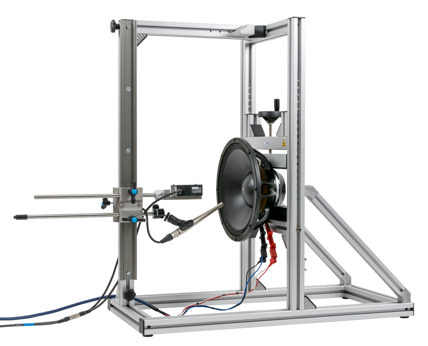
Bill of Material#
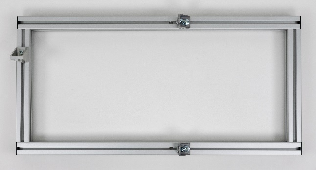
- Bottom frame with pre-mounted T-bolts and Nuts
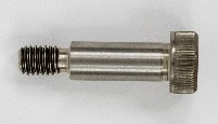
- 2 Shoulder screws
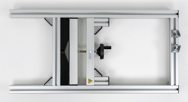
- Holder frame with pre-mounted T-bolts and Nuts
- 2x 45° struts with Sliding blocks and Hex socket head cup screws

- Traverse
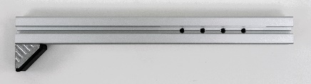
- Sensor slide rail with carriage and two hand screws
 Caution: Do not tighten the hand screws without inserted sensor rods!
 - Sensor slide hand screw

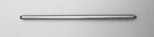
- Laser sensor rod with outer M8 thread

- Microphone sensor rod with outer 1/4” and 3/8” thread
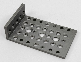
- Laser Bracket rev. 108
- Calibration target rev. 3.0 with hand screw
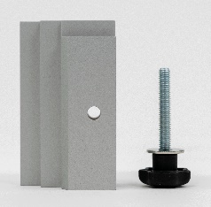
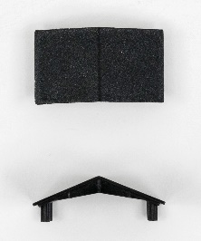
- 4x Plastic covers Type A
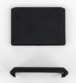
- 4x Plastic covers Type B
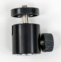
- Microphone Ball Joint with thread reduction
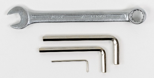
- Tools13 mm wrench6 mm Allen key5 mm Allen key1.5 mm Allen key
Mounting Guide#
Unpacking and Preparing#
While unpacking the parts put them on a solid table or at the ground.
Consider the weight of some of the parts.
Take care that no part will fall down while removing the packaging material.
For example the Sensor Slide Rail (6) is packed together with the Holder Frame (3).
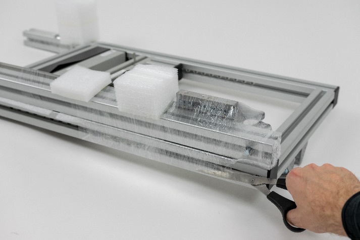
Preparation bottom frame#
Put the bottom frame (1) vertically on a table or on the ground.
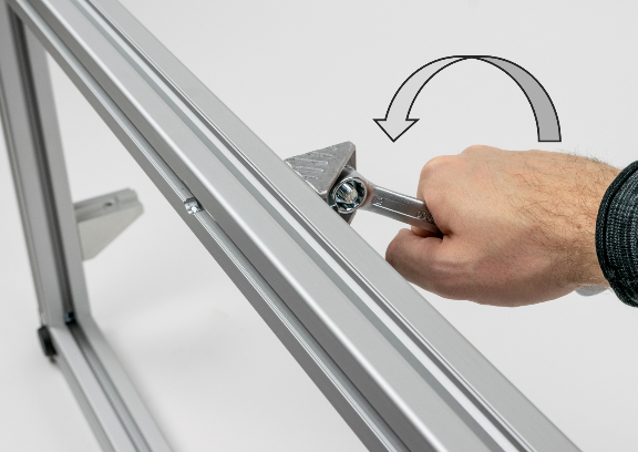
Untighten the pre-mounted screws from the corner brackets.
The corner brackets have to stick at the bottom frame (1).
Mounting holder frame#
Place the holder frame (3) at the fixed brackets at the bottom frame (1).
DIRECTION: Brackets on top of the holder frame (3) must face to the bracket on the bottom frame (1).
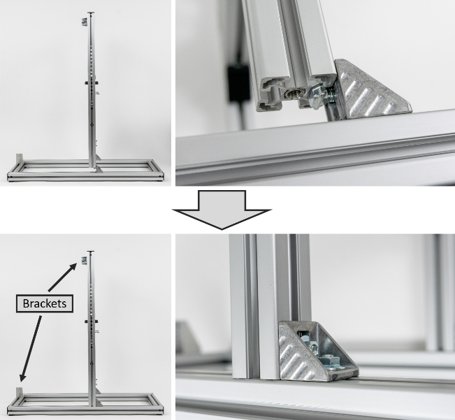
Mount the holder frame (3) with the shoulder screws (2) from the bottom.
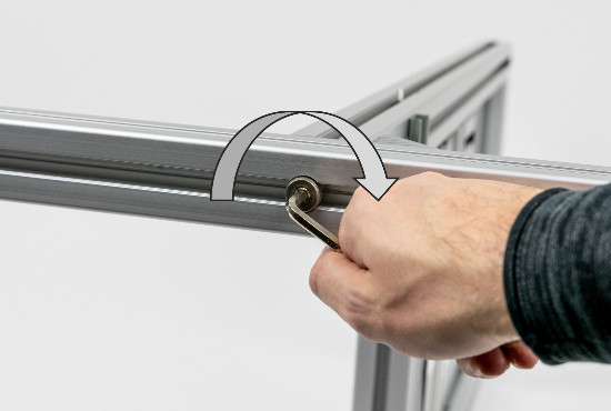
Raise the Pro Stand.
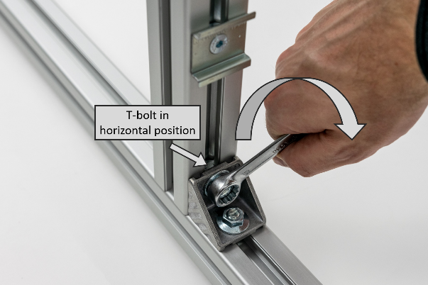
Tighten the T-bolts with the nuts.
Make sure, that the T-bolts are in horizontal position while tightening.
Mounting 45° struts#
Insert the 45° struts (4) into the bottom frame (1) and the holder frame (3).
Ensure that the T-bolts are in parallel to the 45° struts (4) at both ends. Untighten the T-bolt screws until the T-bolts can be turned by 90°.
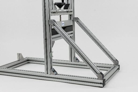
Align the 45° struts (4) in line to the bottom frame (1).
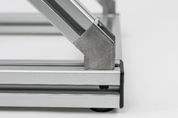
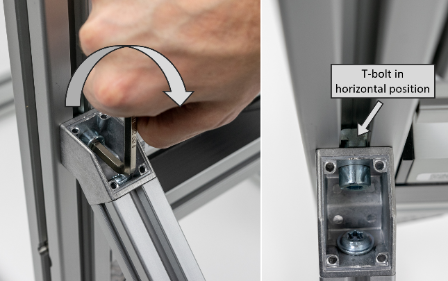
Tighten the screws.
Make sure, that the T-bolts are in horizontal position while tightening.
Mounting of the traverse#
Untighten the pre-mounted screws from the brackets holding to upper traverse (5).
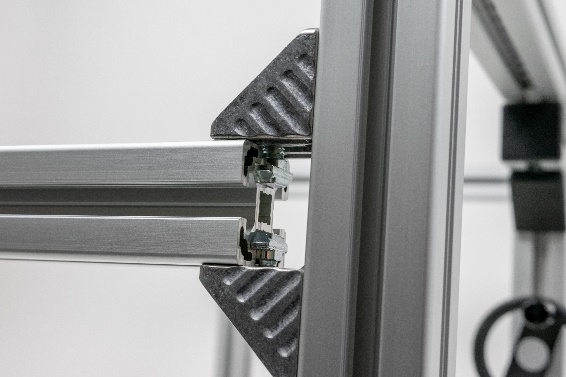
Insert the traverse (5) into the brackets.
Tighten the T-bolts.
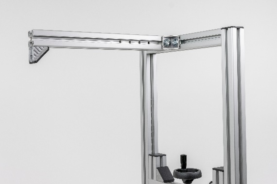
Make sure that the bracket is facing down at the other end.
Mounting of the sensor slide rail#
Insert and tighten the hand screw (7) to lock the carriage of the sensor slide rail (6).
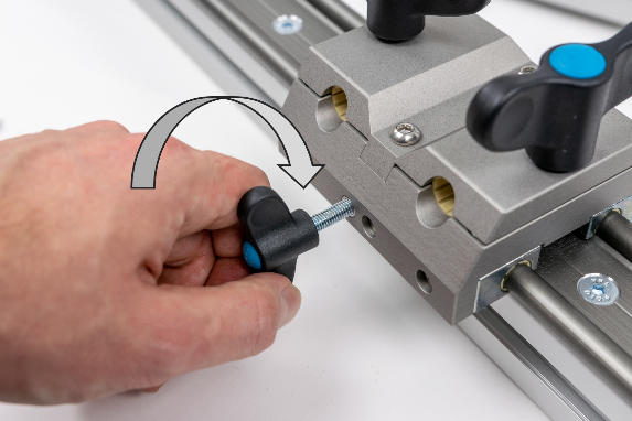
Align the sensor slide rail (6) to the bracket at the bottom frame (1) and at the traverse (5).
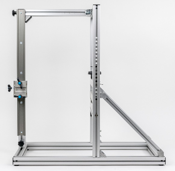
Tighten the hand screws to lock the sensor slide rail (6) to the traverse (5) and the bottom frame (1).
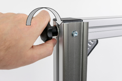
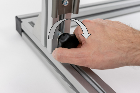
Loose the two big hand screws at the carriage of the sensor slide rail (6) and mount the sensor rods (8 + 9).
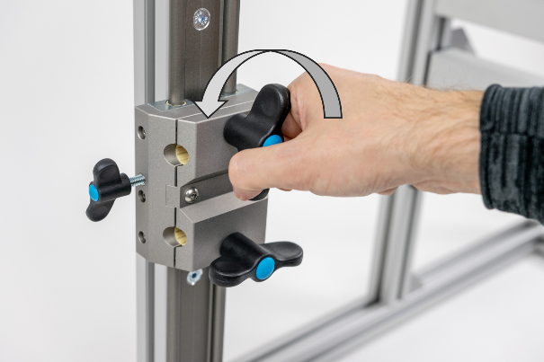
If needed, mount the microphone ball joint (14) to the microphone sensor rod (9)
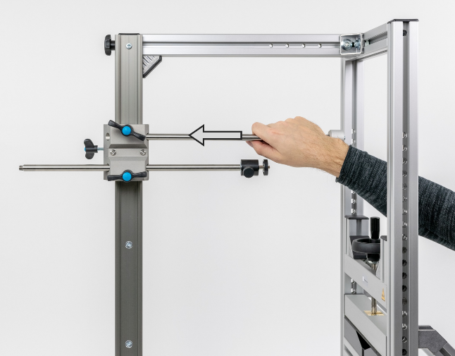
Tighten the hand screws.
Caution: Do not tighten the hand screws without mounted sensor rods!
Mounting of the laser calibration target#
Screw the laser calibration target (11) at the traverse (5) with the hand screw.
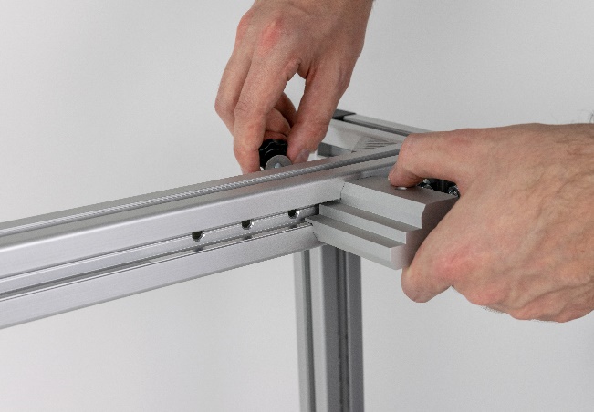
The rearmost hole is recommended.
Make sure that it is facing correctly (positioned on the right side).
Mount the plastic covers#
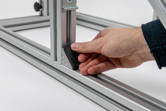
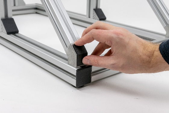
Snap the covers (12 + 13) on all open brackets.
Attach the Laser Controller#
Most laser Controllers have a cap rail clip on their back side which could be used to attach the Laser Controller to the Pro Driver Stand. For the popular Keyence LK-G5000 series Lasers it is recommended to mount the Laser Controller at the bottom frame (1) as shown here. The position of the cap rail could easily be moved to another position just requiring a 4mm Allen key. It is mounted with a removable t-nut.
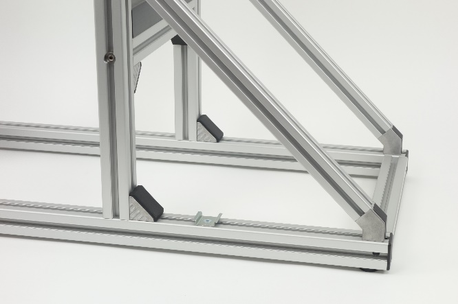
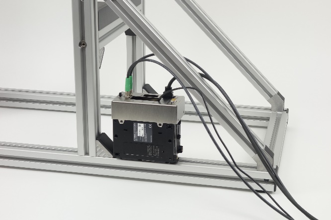
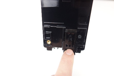
Open the cap rail clip on the backside of the Laser Controller.
Set the Laser Controller onto the cap rail.
Fix it by closing the cap rail clip.
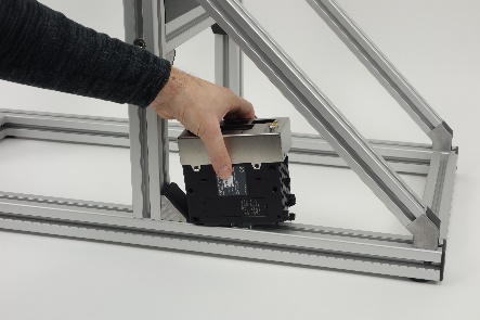
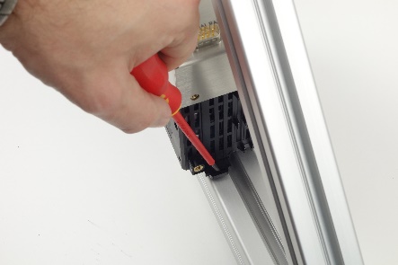
(Alternatively the cap rail clip could be left closed and the Laser Controller will be slipped in sidewards.)
For sensitive acoustical measurements it could be necessary to remove the Laser Controller from the Pro Driver Stand to avoid ratteling noises. The cap rail could aslo be used to mount the Laser Controller at any other lab facility close to the Pro Driver Stand or the Klippel measurement device.
Usage#
Precise sensor adjustment#
The carriage can move up and down by loosen the left hand screw.
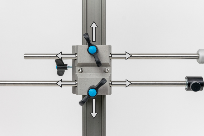
The laser sensor rod and the microphone sensor rod can move left and right by loosen the screws in front.
Rigid clamping of the driver#
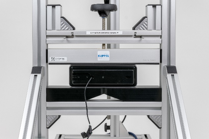
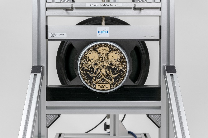
The lower clamp has a rest with three different shapes (plane, V-shaped for tweeters, V-shaped for woofers). This makes it easy to mount the driver in the same center position.
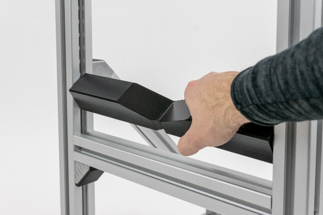
ATTENTION: It is essential to mount the driver in center position, since the pressure for fixing may easily damage the stand at other positions. Similar to the possibility of changing its clamping side, it could easily be taken out of its guidance and replaced by the spare parts which is available separately. Just move it up on one side until it could be taken out. Feed in the replacement lower clamp in the same way.
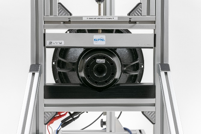
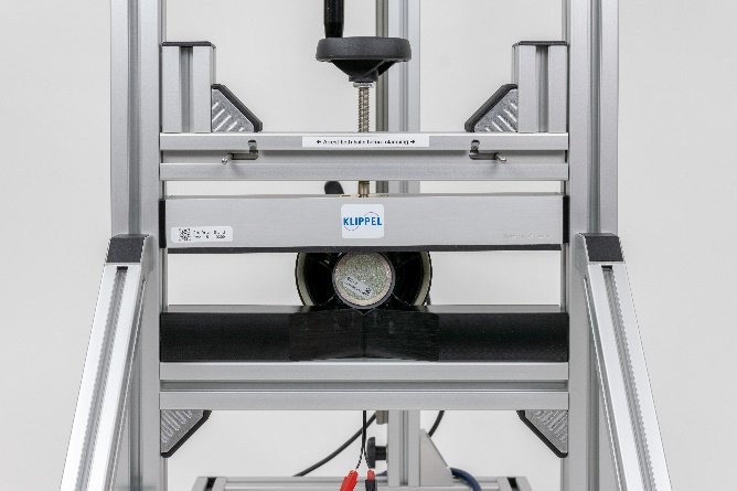
Examples of mounting speakers of different size and shape:
Note
When using the Translation Stage it can start rattling when used in highly stressed environments since it is spring loaded. It comes with a small M3x8mm screw that can be attached from the side to lock the sliding mechanism, hence prevent it from rattling. Torque this screw very gentle to not damage the Translation Stage!
Removable sensor guide#
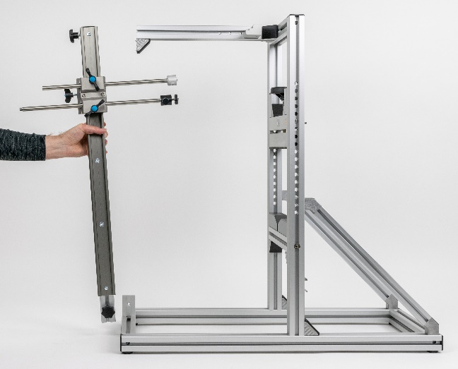
The complete sensor guide may be removed by losing two hand screws. This is convenient when big drivers have to be set into or removed from the stand without changing the position of the laser and microphone.
One-hand operation#
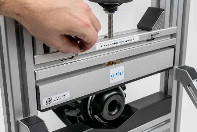
While holding the driver in one hand the cross bolts may be released by the other hand.
Then the driver is clamped by using the center wheel.
Laser sensor plate adjustment#
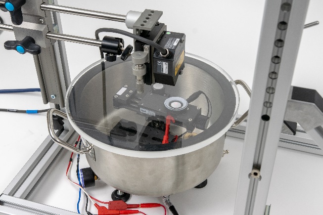
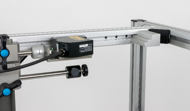
The stand supports the operation of the laser sensor in horizontal and vertical direction. | |
Horizontal default measurement direction
Vertical measurement position as used with vacuum chamber
Laser Calibration Targets#
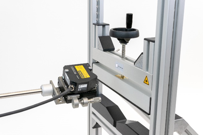
The calibration spacer for the laser calibration is incorporated into the professional driver stand to avoid calibration errors due to tilting.
Additionally a white, matt calibration target is provided by the professional driver stand. It can be used for Laser calibration using a translation stage.
Fixation#
To fix the whole stand at a table, rack or frame all Pro Driver Stands since rev. 1.6 offer four 8.5mm mounting holes at its Bottom Frame. At older revisions this drawing could be used for own modification. M8 screws are recommended. The rubber feet should be placed at the cornes of the frame, close to the fixation screws.
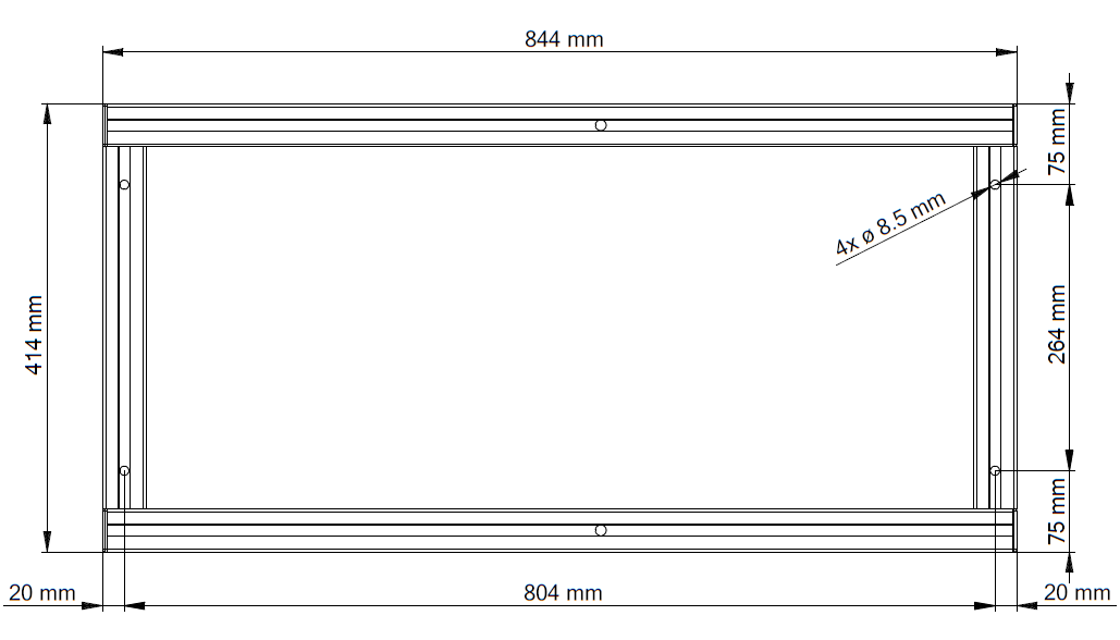
To reduce vibration when heavy transducers should be tested under full power, the whole stand could also be fixed with belts or weighted with sandbags.
Adjustments of the stand#
If the carriage is moving too easily or with too much force, you may adjust the friction of the carriage at the guide.
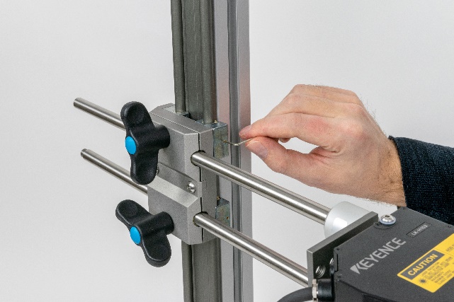
Loosen or tighten the 1.5 mm hex socket screws using the 1.5 mm hex key according to your needs.
If too moch force is required to move the laser or microphone rods inside the carriage, the carriage is most likely deformed must be restored to its original shape. (This usually happens when the hand screws of the carriage are thigtened without rods inserted.)
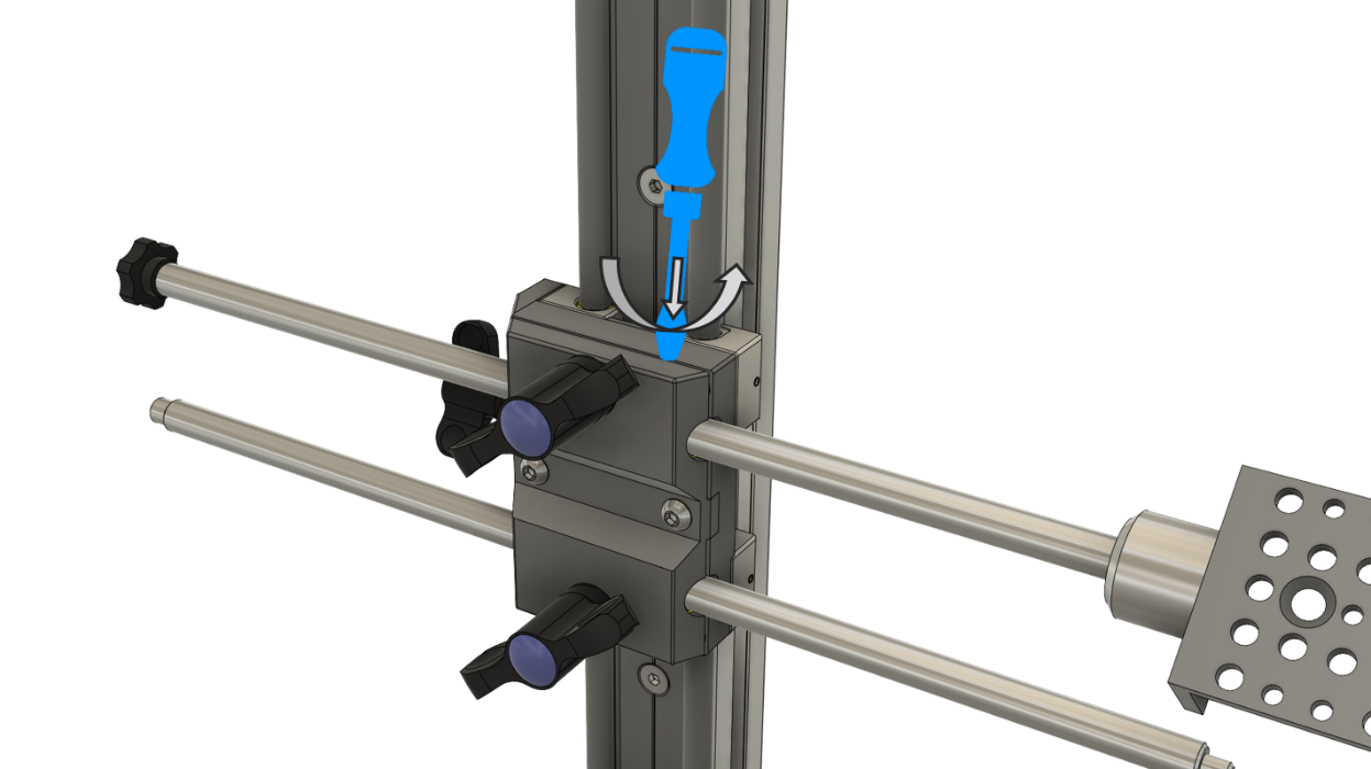
Loosen the hand screws of both the laser and microphone rod
Insert a slotted screw driver into the slot of the carriage and gently pry the carriage open.
Replacement Parts#
- Holder Frame with DUT clamping
- Upgrade kit for rev. 1.0 - 1.2, replacement kit for rev. >= 1.3(needed tools included with Pro Driver Stand)
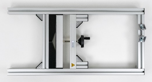
Item Code: 2211-015 Following spare parts are included in the Holder Frame with DUT clamping:Lower Speaker Clamping
Locking Pin with gas spring
Following spare parts are included in the Holder Frame with DUT clamping, due to a difficult replacement procedure they are not offered separately anymore:Upper Speaker Clamping
Upper Speaker Clamping rubber strip
Spindle & insert nut for spindle
- Lower Speaker Clamping
- Replacement part for rev. >= 1.0(no tools needed)
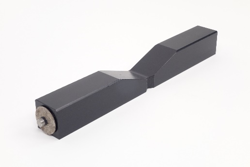
Item Code: 2211-025 - Locking Pin with gas spring
- Upgrade kit for rev. >= 1.0, replacement kit for rev. >= 1.32x locking pin with mounted gas spring + operating lever(pliers needed)
Item Code: 2211-021 - Sensor Slide Rail & Slider
- Upgrade kit for rev. 1.0 - 1.1, replacement kit for rev. >= 1.2, vertical strut with guiding rail & slider, without laser sensor and microphone sensor rod(needed 1.5mm Allen key included)

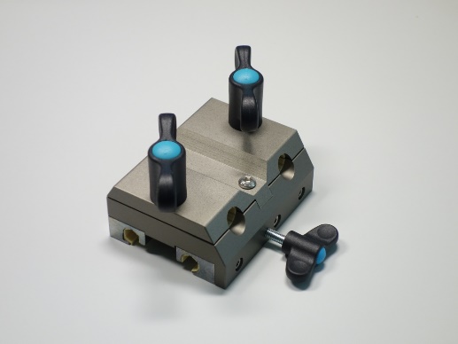
Item Code: 2211-011 - Sensor Slider
- Upgrade kit for rev. >= 1.2, replacement kit for rev. >= 1.5without laser sensor and microphone sensor rod(needed 1.5 and 5mm Allen key included)
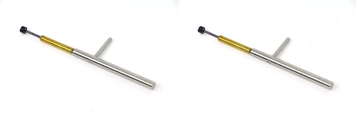
Item Code: 2211-024 - Laser Sensor Rod
- Replacement laser sensor rod with outer M8 thread, 35cm (rod) 38cm (total) length, for Pro Driver Stand rev.1.x(no tools needed)

Item Code: 2211-009 - Microphone Sensor Rod
- Replacement microphone sensor rod with outer 1/4” and 3/8” thread, 38cm (rod) 40cm (total) length, for Pro Driver Stand rev.1.x(no tools needed)

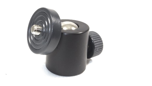
Item Code: 2211-014 - Swivel Head / Ball Joint
- Replacement microphone swivel head with 1/4” outer thread (top side) and 1/4” inner thread (bottom side)(no tools needed)
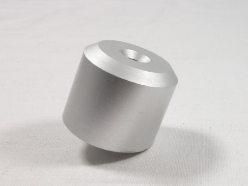
Item Code: 2400-226 - Microphone Sensor Rod adapter
- Adapter from 1/4” inner thread to M8 outer thread for using a 2nd Laser at Pro Driver Stand mic rod(recommended thread locking fluid not included)
Item Code: 2211-023 - Laser bracket rev.108
- For Pro Driver Stand, Micro Speaker Clamping, SPM/MPM Bench, LST (with external boom) Bench or Translation Stage. Could be combined with Laser Plate rev.602 for LK-G and LK-H series and Laser Plate rev.702 for LM10, HL-G and IL series.(needed Allen keys included with Laser Sensors)
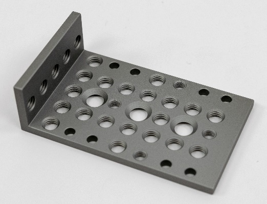
Item Code: 2211-016 - Calibration target rev. 3.0
- Upgrade for rev. 1.0 - 1.3, replacement for rev. >= 1.4For calibration of laser sensor: ANR-1282, ANR-1215, LK-G82, LK-H082, HL-G112,to be mounted at Pro Driver Stand or SPM Bench(no tools needed)
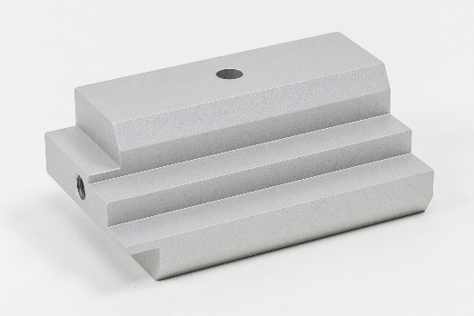
Item Code: 2201-004 - Microphone accessories
- See microphone specification A4Mic Clamp, Swivel Adaptor, Ball Joint
