
ALS – Air Leak Stethoscope#
ALS - Tutorial#
ALS - Overview#
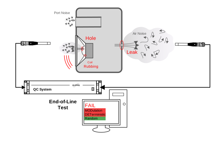
The Air Leak Stethoscope (ALS) is an add-on to the KLIPPEL Analyzer System for the QC end-of-line testing framework. The off-line diagnostics tool is closely related to the end-of-line testing module Air Leak Detection (ALD). Both modules are dedicated to detecting air leaks and other defects in transducers, enclosures and other parts of loudspeaker systems, they share the same signal processing kernel and provide comparable results.
In contrast to the ALD, which is optimized for end-of-line applications using a static measurement setup and relative limits, the ALS was specifically designed for manual defect diagnostics. The test microphone is used as a stethoscope by the operator to trace the origin of air leakage. In addition to the both quantitative and qualitative result display, the isolated defect sound can be auralized with headphones.
Note
This manual focuses mainly on the specifics of the ALS module. Please also refer to ALD Manual to find out more about optimizing the test performance and background information about the unique measures provided.
What is the Goal of this Tutorial?#
This tutorial makes you familiar with the ALS module.
It is divided into the following steps:
See also
You may also take a look at the short ALS tutorial video which can be found on www.klippel.de.
Setting up the Hardware#
Running the ALS task requires the standard QC system setup according to QC User Manual section Connecting the System.
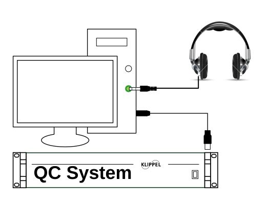
The sketch below shows a typical hardware setup for a passive speaker box including ambient noise measurement and defect auralization.
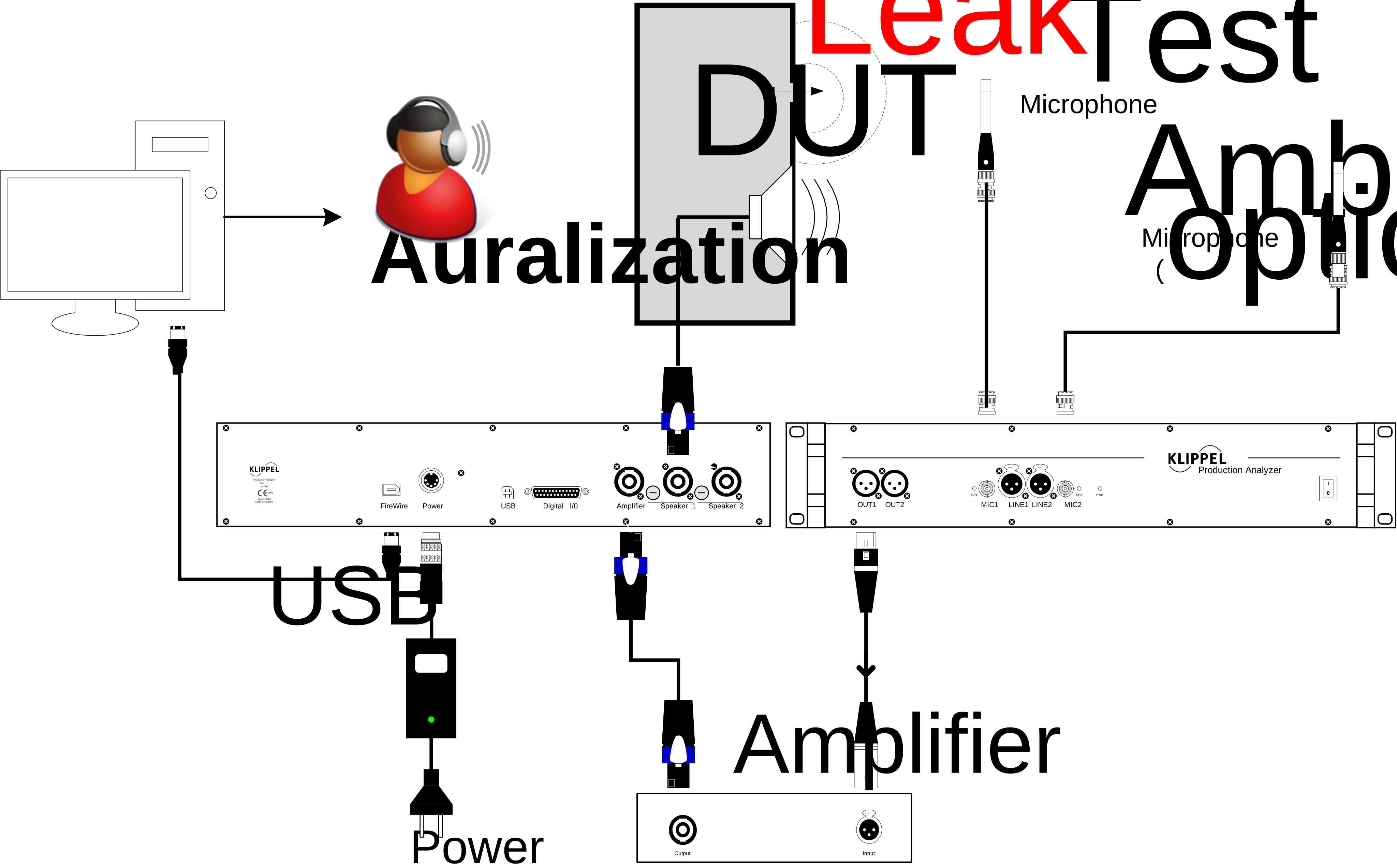
Connect the headphones for auralization to the sound card output (or any other primary audio device) of the host computer. For active systems, no external power amplifier is required.
Creating an ALS Test#
QC System Framework#
Start QC Engineer and select to create a new QC test. If available, navigate to the Air Leak Stethoscope test template. Otherwise select Default (empty) template to create your own test. Choose a suitable test name and click OK.
Click the Measure button to log in.
In case you have selected an empty test template:
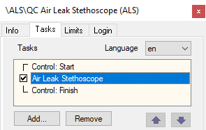
Open property page Tasks
Click the Add… button on property page Tasks
Choose the KLIPPEL task script als.task.klb
The default location is (English Windows version):
%ProgramData%\Klippel\QC\Scripts\Klippel\QC\Modules
Note
The ALS is designed as a standalone application. Although it is possible to add other measurement tasks to your test sequence, it is not recommended. Auxiliary tasks like IO Task may be used, though.
R&D System Framework#
If you are operating the ALS within the KLIPPEL R&D System framework, you may add an ALS test by using the provided operation template:
Create or open a KLIPPEL database
Add a new operation by using the operation icon or
Select and
Choose a name and click OK to create a new QC operation with an ALS task
Click Run
 to log in
See dB-Lab – Software manual for more information.
Setting up the ALS#
Before the first measurement can be started it is necessary to adjust some basic settings of the ALS. A detailed description of all available settings can be found in section Task Parameters.
In the task list select Air Leak Stethoscope to access the modules settings.
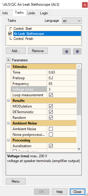
Stimulus#
The category stimulus provides the settings related to the single tone excitation signal.
Time#
With this option the measurement time can be selected from a list of possible values. Only discrete values are provided due to the requirements of the signal analysis. A long measurement time improves sensitivity, but it will reduce the result and auralization update rate. The stated values include a default pre-loop time to achieve steady-state conditions before the data acquisition starts.
Frequency#
This parameter specifies the frequency of the sine tone. The test frequency should be close to the lower frequency range limit of the DUT to ensure high excursion and high sound pressure in the speaker system. Please refer to Overview section Finding the Optimal Stimulus Frequency for more information.
Note
The actual test frequency might slightly differ from the entered value since it is adapted to optimally fit the signal analysis. The actual frequency is displayed in the comment of the Frequency parameter in the ALS Property Page.
Voltage/Level#
Here the RMS voltage of the stimulus signal is specified. Make sure to set a critical stimulus voltage which is high enough to cause defect and leakage symptoms.
Depending on the parameter Output in the category Routing this value either defines the voltage at the speaker terminals for passive systems (Speaker 1 , Speaker 2) or at the selected Line output of the analyzer or 3rd party audio interface for active systems, respectively.
Warning
A too high voltage can damage the speaker.
Loop Measurement#
Activate this checkbox to loop the measurement automatically until canceled by the user. The result display and auralization will be updated in each loop. This mode is recommended for interactive defect localization.
Note
The measurement will only be looped if the reference noise floor has been recorded in Limit Calculation Mode.
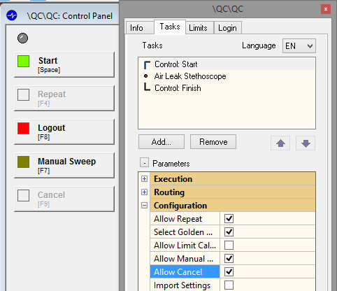
If this setting is activated, make sure that the Cancel button is activated and shown in the Control Panel. You make activate this function in as shown below.
Measurement#
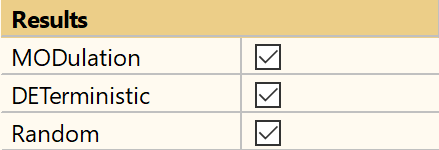
This parameter category defines which parameters shall be measured by the ALS. You may activate all available measure to cover the full range of distortion related to all kinds of possible loudspeaker defects.
In contrast to ALD, the measures (in total seven) are grouped in subsets according to their characteristics:
MODulation (modulated noise)
MODabs (absolute)
MODrel (relative)
DETerministic (deterministic distortion)
DETabs (absolute)
DETrel (relative)
DET(L)abs (absolute)
DET(L)rel (relative)
Random (sporadic distortion)
You may activate or deactivate each group as a whole.
Refer to section Definition of Measures for more information on the available measures.
Processing#
Auralization#
Activate the checkbox Auralization to enable audio output for the Operator. The isolated defect distortion signal is sent to the primary audio device of your PC. This helps the operator tracing defects without supervising the result on the screen. Additionally, subjective evaluation of the defect is made easy while protecting the ears.
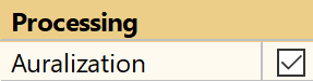
The Auralization offers several advanced parameters for optimizing performance; take a look at section Auralization for more information.
Note
Make sure that the correct primary audio device is selected in the Windows playback device panel. Adjust the system volume to a low value to prevent hearing damage. The volume may be adjusted during operation.
Performing an ALS Measurement#
After basic setup parameters have been set, the first ALS can be performed.
First Measurement#
Hit Start button in the Control Panel to start your first measurement. The test tone is played back once; all results are displayed in Summary Window. Without having recorded the reference background noise floor the Summary Window only shows the plain result levels of the defect measures.
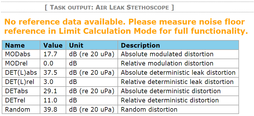
Note
The measurement is not repeated automatically unless limits have been defined.
Noise Floor and Limits#
In order to activate the custom result output of the ALS, it is required to “calibrate” the measurement by measuring the acoustic background noise floor which defines the maximal sensitivity of your ALS measurement. To do so, activate Limit Calculation Mode and perform one or more measurements. No stimulus is played back, the resulting thresholds are independent of the actual DUT connected. This is different to end-of-line testing using ALD where the limits are typically based on the reference DUT’s.
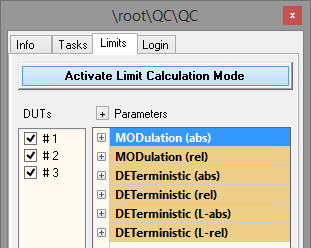
The threshold limits for the individual distortion measures are derived automatically from the reference measurements by clicking Calculate. A summary table shows all results. Make sure that the reference measurements are consistent.
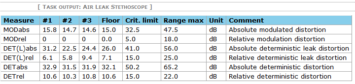
There are two threshold limits calculated for each measure. Range max defines the saturation limit representing excessive distortion. The Critical limit defines the level where distortion gets significant and may indicate a possible defect.
Main Measurement#
After the distortion threshold limits have been derived from the noise floor, they are applied in normal measurement mode to evaluate the measured distortion qualitatively. Click Start to see how the result display has changed in Summary Window. The measurement is now repeated automatically, if requested.
Summary Window#
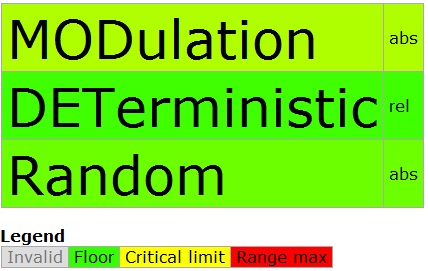
A color bar display above the result table represents the distortion levels in an intuitive and qualitative way. One bar stands for one measure group (e.g. MODulation), the suffix in the second column indicates which sub-measure is currently displayed (e.g. abs for absolute distortion level).
The actual distortion level is coded by the background color of each bar. A green color indicates that the currently measured level is close to the noise floor as measured in Limit Calculation Mode.
Placing the microphone far from the DUT should result in a “green” display as shown below.
Move the microphone towards the DUT and slowly “scan” the surface. In case Auralization has been activated the isolated distortion signal should be played back periodically via your audio device.
If the distortion levels are rising significantly above reference level towards Critical Limit, the color will change to yellow and orange.
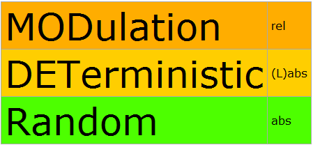
The color will turn to deep red in case excessive distortion is measured. This should be the case if the microphone very close to an air leak or a defective driver.
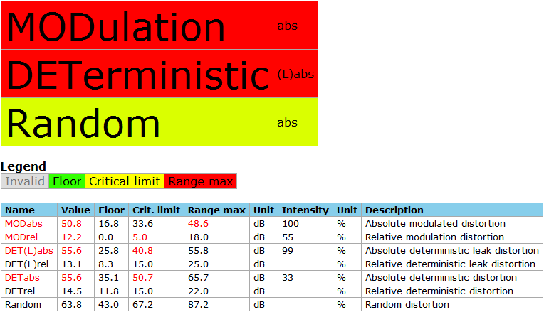
The result table indicates which measures are critical and which thresholds have been violated using red highlighting.
Audio Playback#
In case Auralization has been activated and a playback device is connected to your PC you should be able to hear the isolated distortion signal. It played back right after each measurement including a short break between each run.
Working with the ALS Task#
Auralization#
The ALS Auralization feature was designed to enhance the objective measurement results with subjective evaluation focusing on distortion caused by typical loudspeaker defects. Activate this feature to play back the isolated defect distortion via the sound card of your PC. This feature supports the operator in tracing defects without supervising the screen. Additionally, the distortion can be evaluated subjectively. Using sound insulating headphones even ear protection may be provided in case the test is performed at high sound pressure levels.
Setup#
Plug your playback device (e.g., powered speakers or headphones) into the audio output of the host PC’s sound card or any external audio interface connected.
Note
It is recommended to use headphones instead of speaker to minimize interference of the playback signal picked up by the microphone with the measurement results. However, as the audio signal is not synchronized with the measurement there is no danger of feedback loops.
Check your Windows playback audio device to make sure that the correct audio output is selected as your default audio device using the loudspeaker symbol in the task bar.
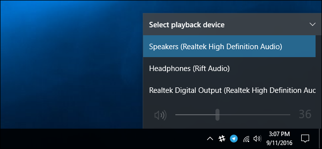
If your playback device does not provide a volume control, adjust the output device volume here as well. Start with a low value before running the test to prevent damage to the ears.
Parameters#
The Auralization feature provides several parameters to modify audio signal processing in ALS parameter section Processing.
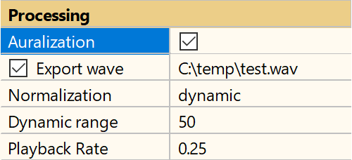
Playback Rate#
This relative factor allows to adjust the playback sample rate in order to slow down and reduce pitch of the exported wave file to better analyze the time patterns and pitch of the filtered distortion signal. The lower the value, the slower is the playback speed and the pitch. A factor of one means that the signal is played back with original speed.
Normalization#
This drop-down list affects the playback volume of the auralization audio signal. Off means that the distortion signal is played back as recorded, no normalization is applied. As the isolated distortion is usually very low level, this setting results in a very low audio output.
To apply a static normalization to the output signal, select -3 dB. The peak level of the audio signal will be normalized to -3 dB (full scale). This has a drawback as the absolute level cannot be evaluated by the operator. Approaching a defect will not result in an increasing level. Background noise is boosted in case there is no defect distortion.
Dynamic mode in contrast, applies a smart normalization algorithm. The playback level is adjusted within a dynamic range which is defined by parameter Dynamic range. The low-end level is derived from the noise floor measurement (see Noise Floor and Limits), the upper limit is full scale. In a noisy environment set a low Dynamic range.
Export wave#
Using this option, the audio signal may be exported to a WAVE file. This can be used for diagnostics, training, evaluation or further signal analysis.
Note
The file is overwritten in each test run. Therefore, it is recommended to deactivate Loop measurement and perform single shot measurements for exporting wave files.
Ambient Noise Detection#
Although it is less relevant for diagnostic applications, the ALS provides ambient noise detection, optionally. The algorithm and setup parameters are based on the ALD task, please refer to ALD Manual for more information. As the threshold limits are not based on reference measurements, the algorithm is slightly modified and less sensitive.
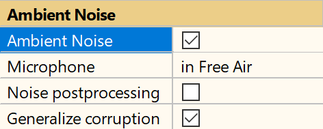
If Ambient Noise is activated and set up correctly, any ambient noise corruption will be indicated in the colored result bar diagram by an invalid result with grey background color. Corrupted measurements are not auralized or exported.
Note
The default microphone input channel for noise monitoring is Mic2. However, the input routing may be set manually or automatically depending on the global routing settings in Control:Start task. For more information, please refer to QC User Manual section Routing / Delay / GPIO Control.
Adjusting Limits#
According to section Noise Floor and Limits the threshold limits are calculated automatically using default calculation parameters. However, the threshold parameters may be customized for each available measure.
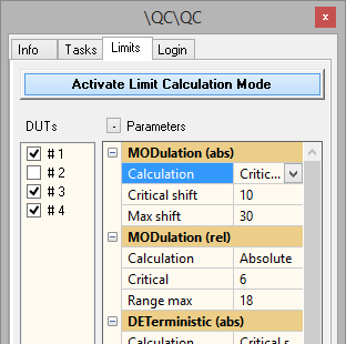
In ALS task threshold limits for the following measures may be defined:
- MODabs
absolute, shift
- MODrel
absolute, shift
- DET(L)abs
absolute, shift
- DET(L)rel
absolute, shift
- DETabs
absolute, shift
- DETrel
absolute, shift
- Random
absolute, shift
The following limit types are thus available:
- Absolute
Gives absolute values for the uppe limit. This value is independent of the average value of the reference units.
- Shift
The shift value is added to the average value of the reference units for the upper limit.
For additional information about limit calculation mode see Limit Calculation.
However, limit parameters slightly differ to other modules because the ALS provides two limits per measure, the Critical Limit (warn or PASS/FAIL limit) and Range Max Limit which defines the saturation limit.
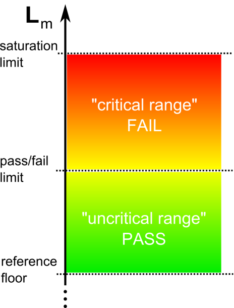
Therefore, two limit parameters are provided for each measure to independently define both limits relatively (Critical shift and Max shift) or absolutely (Critical and Range max).
ALS - Reference#
Task Parameters#
The table below lists and describes all available task parameters of the ALS task.
Stimulus#
- Time
Measurement Time (drop-down list with discrete values), default pre-loop time included
- Preloop
duration of stimulus pre-excitation before measurement starts to ensure steady-state conditions
- Frequency
Stimulus frequency; Value is adjusted to a discrete frequency defined by signal analysis
- Voltage (RMS)
RMS stimulus voltage at speaker terminals or respectively at Line output of the analyzer or output device (depends on output routing settings)
- Loop measurement
Measurement is repeated automatically
Routing#
- Custom File for Import
path of task-specific custom wave file for processing (raw data import) (only available in case of wave file processing)
- Output
- Options: Speaker 1,2 (loudspeaker terminals); OUT 1, 2, 1+2
Select output of analyzer or playback device. The test voltage/level is specified at selected output (only available if global output routing is set to controlled by task)
- Speaker 1 connect
Connect Speaker 1 to power amplifier output
- Speaker 2 connect
Connect Speaker 2 to power amplifier output
- Output Channel
select output channel(s) of playback device (only available for 3rd playback audio device output and if global Output is set to controlled by Task)
- Input channel
- Options: Mic 1, Line 1, Mic 2, Line 2
Select input channel for measurement channel 1. (only available if global input routing is set to controlled by task)
- Noise channel
- Options: Mic 1, Line 1, Mic 2, Line 2
Select input channel for ambient noise channel. (only available if Noise Monitoring measurement is active and global input routing is set to controlled by task)
- Test Sensor Input Channel
select channel of capture device or wave file for test sensor signal (Only displayed with 3rd capture device or Execution Mode - Load Input Signals and if Test Sensor Input is set to controlled by Task)
- Noise Sensor Input Channel
select channel of capture device or wave file for noise sensor signal (Only displayed with 3rd party capture device or Execution Mode - Load Input Signals and if Test Sensor Input is set to controlled by Task)
- Digital Output
- Options: Format 1: [Value1, Mask1; Value2, Mask2; …]; Format 2: [Value1; Value2; …]
Bit mask for digital output (GPIO) of KLIPPEL analyzer (e.g. for multiplexer control), pins are set before test. Rows correspond to pins 24, (11), 5, 17, 4, 16, 3, 15, 2
- Delay Before
Set delay before measurement starts (after GPIO setting, if requested)
- Delay After
Set delay after measurement (before next task starts)
Results#
- MODulation
Measure modulated noise (absolute and relative)
- DETerministic
Measure deterministic distortion (general and leak, both absolute and relative)
- Random
Measure absolute Random distortion
Ambient Noise#
- Noise Monitoring
Activate ambient noise measurement
- Microphone
- Options: In Free Air, In Box (attenuation 15 dB), Custom (use attenuation curve)
Position/location of test microphone; Specify the measurement setup to apply box attenuation, if a measurement enclosure is used (available if Noise Monitoring is active).
- Attenuation
- Format:
[Frequency in Hz, Attenuation in dB]Acoustical attenuation of ambient noise at near field mic due to box enclosure (available if Ambient Noise is active and Microphone – Custom is selected)
- Noise postprocessing
Activate ambient noise post-processing; Checks the consistency among the MODulation measures to identify corrupted measurements; This feature should only be used if no ambient noise mic is available.
- Generalize corruption
All FAIL verdicts are invalidated, if at least one measure was identified as corrupted by ambient noise. This option is active by default to guarantee valid measurement results. (available if Noise Monitoring is active)
Processing#
- Auralization
Enable playback of distortion signal via default audio device
- Export wave
export distortion signal to wave file for auralization
- Normalization
- Options: Off, -3 dB (full scale), Dynamic (auto)
Select level normalization mode (level adjustment) for wave export and auralization (available if Auralization or Export Wave is activated)
- Dynamic range
Set dynamic (level) range for dynamic wave normalization mode; reference level based on noise floor measurement; This is an exclusive parameter for Normalization - Dynamic.
- Playback Rate
relative playback sample rate for wave export - affects speed and pitch; decrease value to improve audibility of HF noise, transients and fast patterns
- Input Gain 1
Input gain for KLIPPEL analyzer inputs corresponding to Mic1/Line1
Note
The effective range and available gain steps depend on used analyzer/card, please refer to hardware specification.
- Input Gain 2
Input gain for KLIPPEL analyzer inputs corresponding to Mic2/Line2
Note
The effective range and available gain steps depend on used analyzer/card, please refer to hardware specification.
- Recording Delay
Fixed delay of captured signal relative to generator (in addition to hardware or measured delay)
Display#
- Font size
- Unit: pt
Main font size of color bar diagram
- Display mode
- Options: Dynamic; Separate; Only abs; Only rel
define how results shall be displayed by the color bar diagram:
Dynamic: display only main groups, most significant measure is displayed
Separate: display all measure individually
Only abs: only display absolute measures
Only rel: only display relative measures
- Combined DET display
display DET and DET(L) in one group in color bar diagram
Definition of Measures#
Both ALS and ALD provide the same signal processing and measures. Please refer to ALD Manual for detailed definitions.
Here is a short overview of the provided measures:
- MODulation - MODabs
The \(MOD_{\text{abs}}\) represents the absolute peak SPL of amplitude modulated (AM) noise. Thus, it perfectly quantifies turbulent flow noise as caused by leaks and other defects causing periodic noise (e.g. coil rubbing). \(MOD_{\text{abs}}\) It should be used in conjunction with the \(MOD_{\text{rel}}\) as a qualitative measure, because \(MOD_{\text{abs}}\) can be influenced by other noise sources.
- MODulation - MODrel
The \(MOD_{\text{rel}}\) is a relative measure derived from \(MOD_{\text{abs}}\) for qualitative evaluation. The amplitude of the modulation envelope is related to the noise floor to give information about the defect symptoms. It may be compared to the modulation index in amplitude modulation. As an absolute indicator for modulated noise it is useful to detect leakage and similar defects even without reference limits. Values significantly above the minimum of 0 dB (default: 5 dB) indicate turbulent leak noise or other defects causing semi-random distortion. Thus, it verifies the quantitative results of \(MOD_{\text{abs}}\).
- DETerministic - DET(L) abs
The \(DET(L)_{\text{abs}}\) is a high-level measure exploiting specific harmonic distortion caused by air leaks. It is useful for very small leaks which do not generate flow noise. It represents the averaged deterministic distortion peak SPL. In contrast to the MODulation measures, \(DET(L)\) is a unique symptom for small leaks with weak air flow. Thus, it cannot be masked by port turbulences und provides high sensitivity to identify leaks.
- DETerministic - DET(L)rel
The \(DET(L)_{\text{rel}}\) is derived from \(DET(L)_{\text{abs}}\) as a relative level measure. It is comparable to a crest factor of the average leak distortion.
- DETerministic - DETabs
The \(DET_{\text{abs}}\) is a measure for high order harmonic distortion. It is a measure for deterministic (strictly periodic) Rub&Buzz distortion as caused by hard limiting or loose wires. The measure represents the peak value of the deterministic distortion on an absolute scale in dB(SPL).
- DETerministic - DETrel
The \(DET_{\text{rel}}\) is derived from \(DET_{\text{abs}}\) as a relative level measure. It represents the crest factor of high-order harmonic distortion (e.g. Rub&Buzz).
- Random
Random is a measure for impulsive distortion which happens sporadically (e.g. caused by loose particles). It represents the peak SPL of non-deterministic distortion.
