
SCN-NF – SCN Near Field Add-On - Assembly#
Safety Instructions#
English: Instructions for Operation#
Operation of the machine is restricted to authorized personnel only.
Authorized personnel are required to:
read, understand and follow all instructions in the “R&D System User’s Guide SCN Near Field Add-On” and “SCN Near Field Add-On Mounting Instruction”
follow all instructions given in Safety Instructions.
KLIPPEL is not liable for any damage or injury caused by disregard of the safety instructions, or any instruction in the manual.
German: Anweisungen für die Bedienung#
Der Betreiber hat dafür zu sorgen, dass die Bedienung des Nahfeld-Scanners nur von geschultem, technisch ausgebildetem Personal durchgeführt wird.
Die Personen müssen die Bedienungsanleitungen “R&D System User’s Guide SCN Near Field Add-On” und “SCN Near Field Add-On Mounting Instruction” und deren Sicherheitsbestimmungen gelesen und verstanden haben und verantwortungsvoll die Bestimmungen beachten.
KLIPPEL übernimmt keine Haftung für Schäden oder Verletzungen verursacht durch die Nichtbeachtung der Sicherheitsbestimmungen oder Instruktionen der Bedienungsanleitungen.
Introduction#
How screws are distinguished#
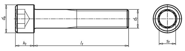
Cylinder head screw#
DIN 912 / ISO 4762
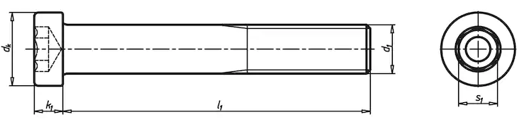
Low-profile cylinder head screw#
DIN 6912
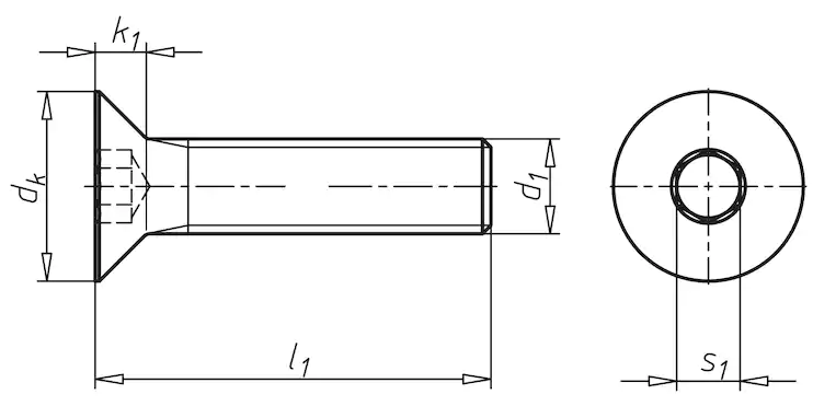
Countersunk head screw#
DIN 7991 / ISO 10642
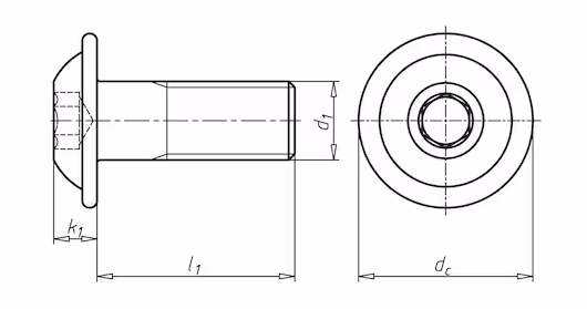
Half round head with collar screw#
ISO 7380-2
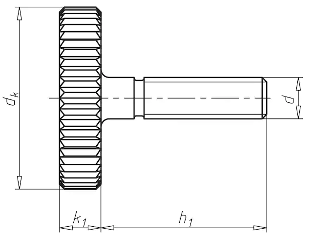
Knurled screw#
(for hand operation)
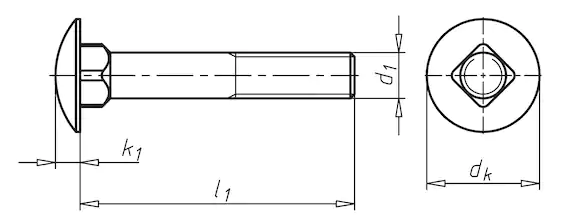
Round head screw with square neck#
DIN 603
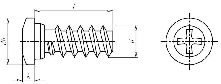
Pan head euro screw#
(for wood applications)
Notation example#
M6x40 means: thread diameter d = 6mm and length l = 40 mm. Please note that the length of countersunk head screws is measured over the whole screw including the head!
Provided tools#
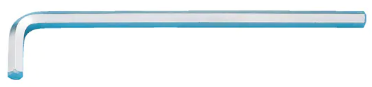
Hex Keys#
5 mm, 3 mm
Combination wrench#
10 mm

Attention: Only use the provided tools for the assembly. Do not use power tools. Do not over-tighten screws!
Setting up the Hardware#
Microphone sensor arm assembly#
Identify the serial number of your SCN unit. The serial number is located on the backside of the unit.
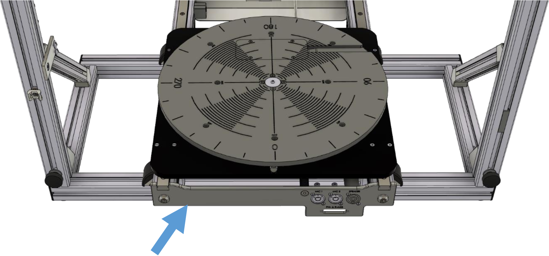
Refer to the sensor arm mounting instructions in chapter Mounting instruction for SCN with SN200 and above for later SCN units with a serial number of 200 or above (SN >= 200).
Refer to the instructions in chapter Mounting instruction for SCN with SN 199 and below for earlier SCN units with a serial number of 199 or below (SN <= 199). larger.
List of Parts#
Box 1#
Pcs. |
Description |
|---|---|
1 |
Microphone Sensor Arm Assembly (pre-mounted) |
1 |
Upper Z-Axis Mounting Block |
1 |
Lower Z-Axis Mounting Block |
Bag 1#
Pcs. |
Description |
|---|---|
1 |
M8x20 low profile screw |
2 |
M5x30 countersunk screw |
1 |
M6x30 screw |
2 |
M6x16 knurled screw |
5 |
M6 washer |
1 |
Microphone Holder |
1 |
UNC ¼“ knurled screw |
4 |
Cable Clips |
Mounting instruction for SCN with SN200 and above#
Step 1: Z-Axis Mounting Position#
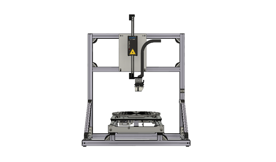
Use the manual movement of the Motor Control of your SCN Unit to park the Z-Axis in a central position as shown in the picture.
Step 2: Laser Sensor Disassembly#
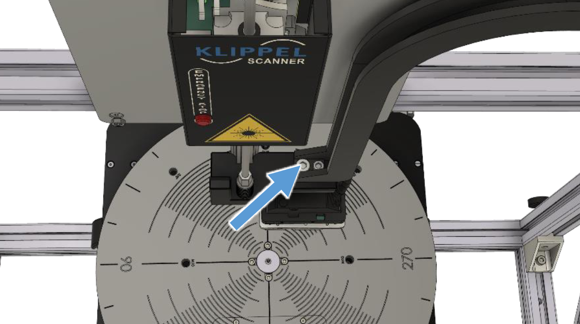
Loosen and remove the M8x16 low profile screw which mounts the Laser Sensor.
Step 3 - 6: Lower Z-Axis Mounting Block Assembly#
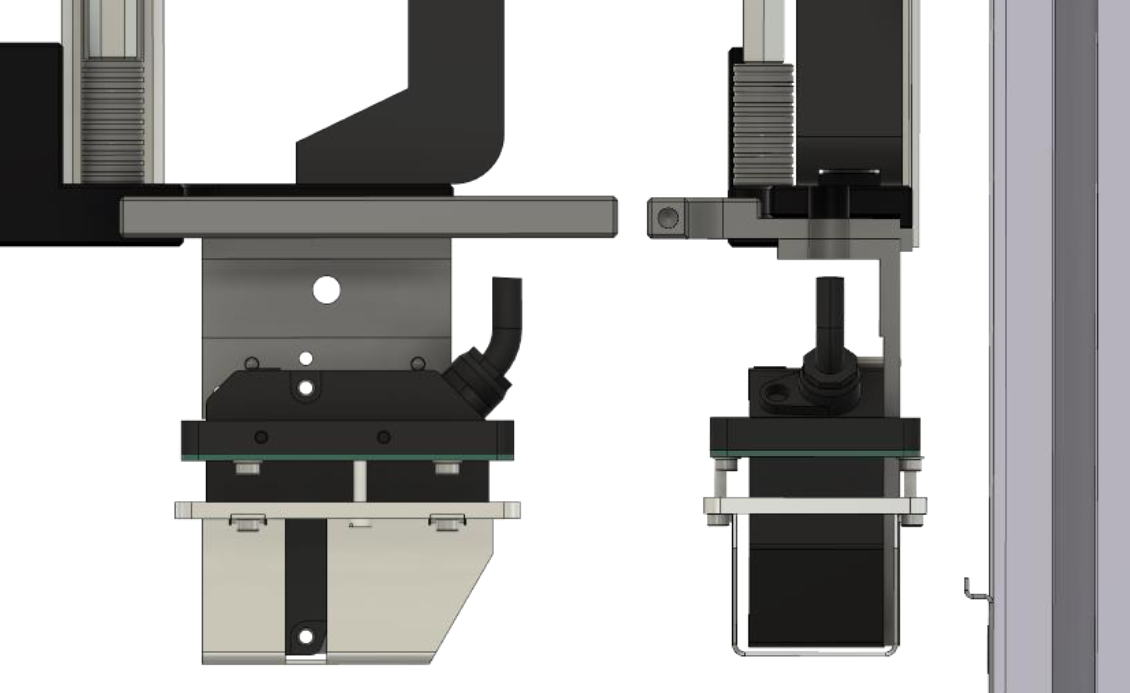
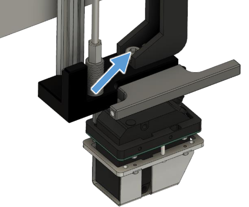
Insert the Lower Z-Axis Mounting Block between the bottom end of the SCN Z-Axis and the Laser Sensor.
Remount the Laser Sensor and together with the Mounting Block using the M8x20 low profile screw provided with the Add-On. (Do not fully tighten th screw yet.)
Align the Mounting Block to the back edge of the bottom end of the SCN Z-Axis and align the Laser Sensor to the back edge of the Mounting Block as shown in the upper right picture.
Tighten the M8x20 screw to lock both Mounting Block and Laser Sensor in place.
Step 7: Upper Z-Axis Mounting Block Disassembly#
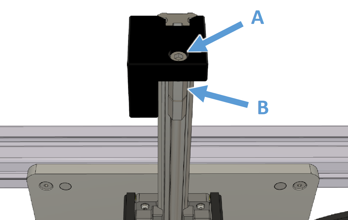
Counter the upper M6 nut (B) of the Z-Axis with a wrench in order to loosen and remove the M6x16 screw (A) at the top end of the SCN Z-Axis.
Pay attention not to lose the M6 washer located between the upper M6 nut (B) and the Top-End Block of the Axis!
Step 8 - 10: Upper Z-Axis Mounting Block Assembly#
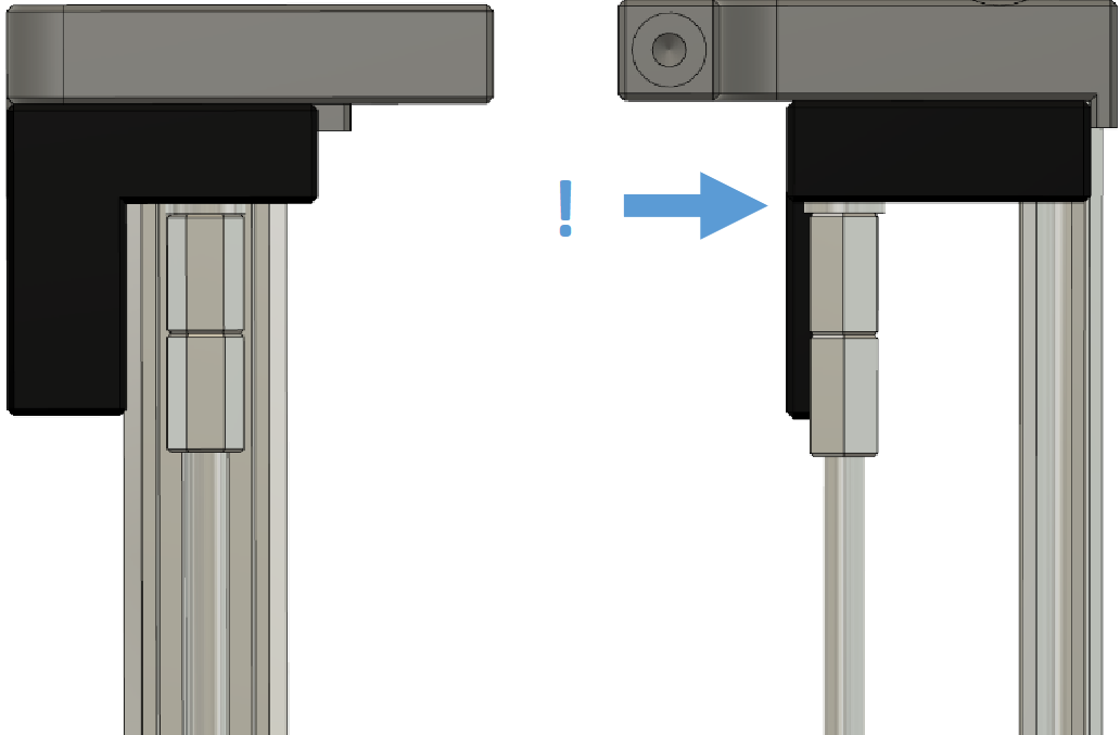
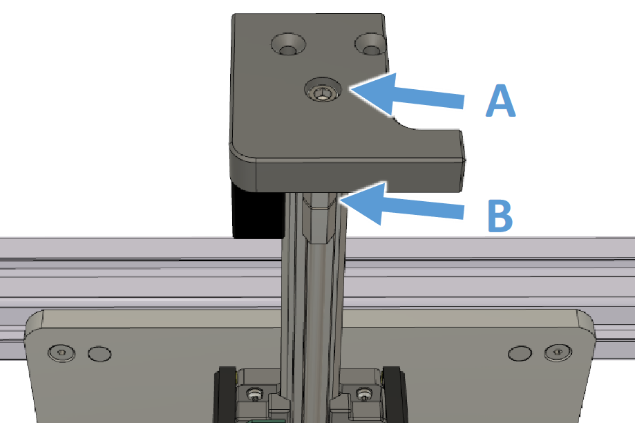
Place the Upper Z-Axis Mounting Block on top of the SCN Z-Axis
Align the back edge of the Mounting Block to the back edge of the Z-Axis as shown in the upper right picture.
Mount the Block using the M6x30 screw (A) provided with the Add-On. Counter the upper nut (B) with a wrench before tightening screw (A).
Pay attention that the M6 washer located between the upper M6 nut (B) and the Top-End Block of the Axis is in place!
Step 11, 12: Upper Microphone Sensor Arm Assembly#
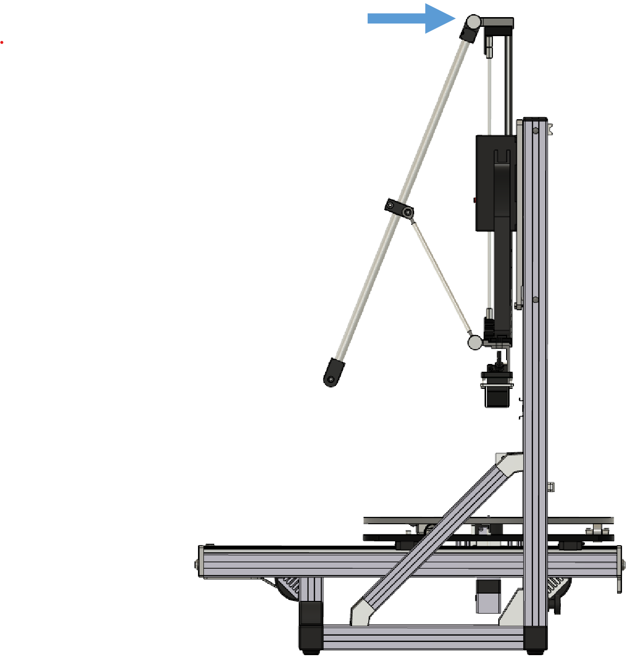
Prepare the Microphone Sensor Arm by removing the packaging from the pre-mounted assembly.
Mount the Microphone Sensor Arm with the integrated knurled screw to the Upper Mounting Block.
Step 13, 14: Lower Microphone Sensor Arm Assembly#
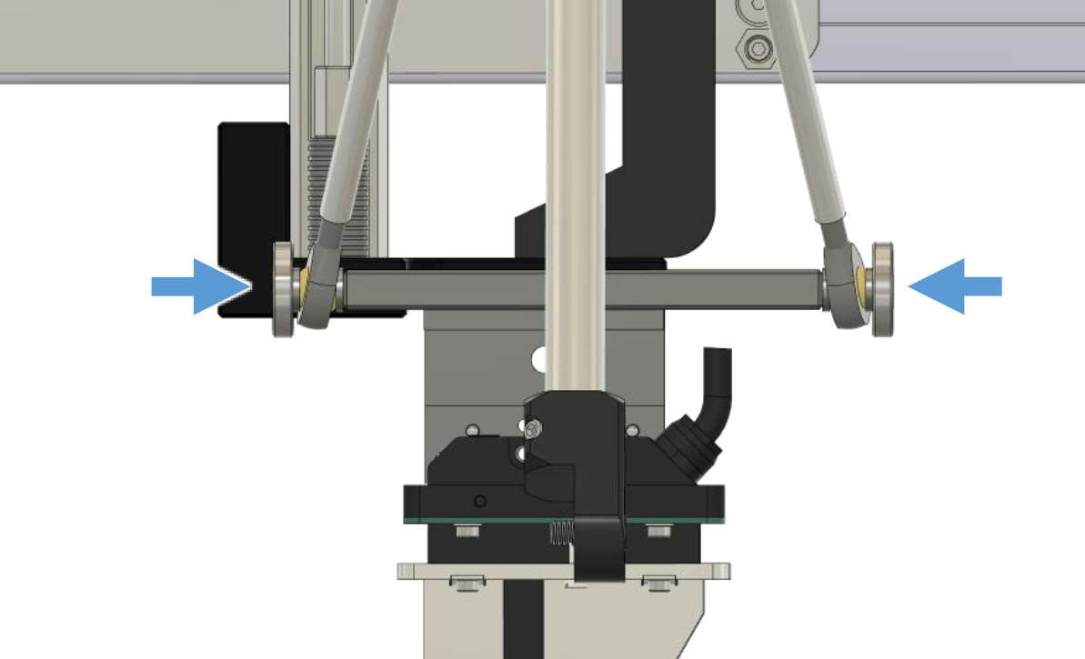
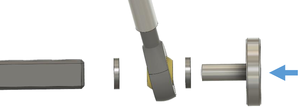
Mount the Support Arms of the Microphone Sensor Arm Assembly to the Lower Mounting Block using the M6x16 knurled screws provided with the Add-On.
Place a M6 washer between the Mounting Block and the Support Arm bearing and another M6 washer between the Support Arm bearing and the knurled screw as shown in the picture.
Step 15: Microphone Holder Assembly#
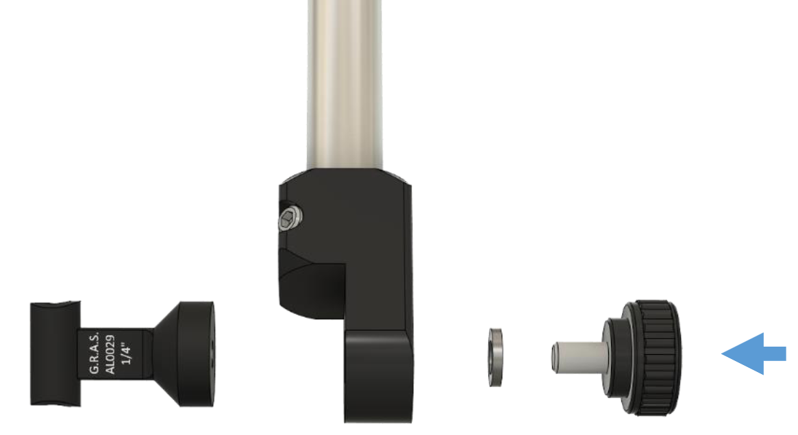
Mount the Microphone Holder supplied with your measurement microphone with the UNC ¼” screw and a M6 Washer provided with the Add-On
Step 16, 17: Cable Assembly#
Install your Measurement Microphone in the Holder.
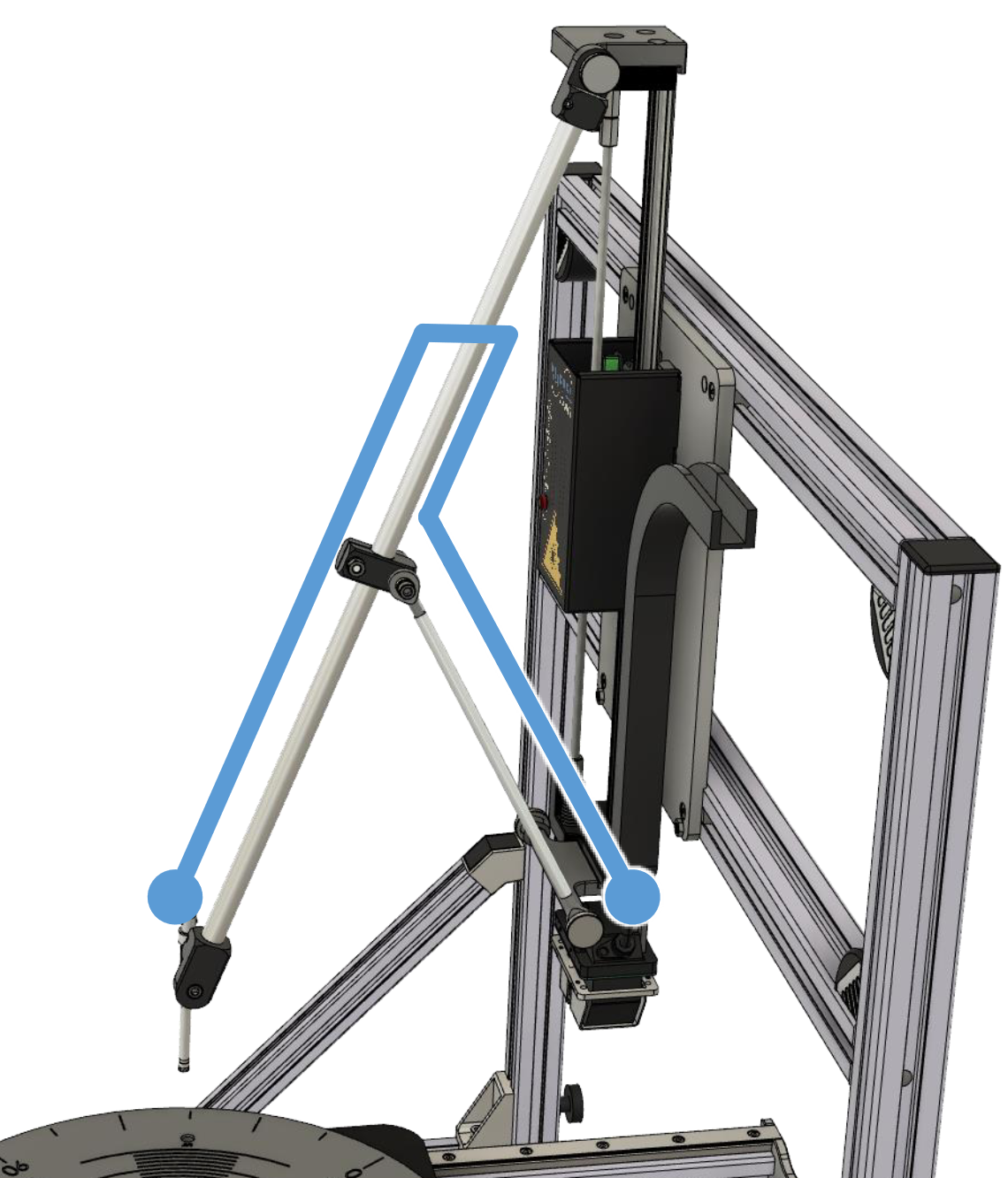
Run the short 1 m extra thin BNC Cable as shown in the picture with small loop. Use Cable Clamps to fix the Cable on the Sensor Arm an Zip Ties to fix it to the smaller Support Arm.
Step 18 - 21: Cable Chain Assembly#
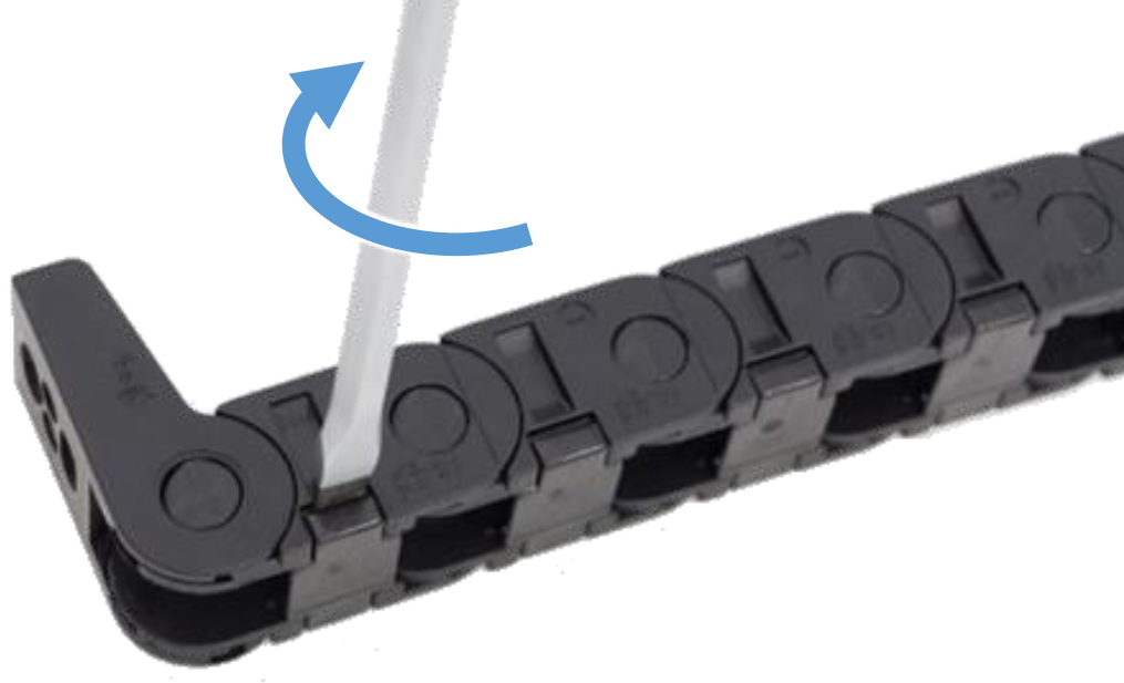
Open the clips of the cable chain on the SCN Z-Axis using a slot screw driver.
Insert the 2 m extra thin BNC Cable into the cable chain and loc the clips again.
Link both extra thin BNC Cables together with a BNC Coupler.
Link the standard BNC Cable supplied with your mic to the other end of the the 2 m extra thin BNC Cable also using a BNC Coupler.
Proceed the setup with the Baffle assembly.
Mounting instruction for SCN with SN 199 and below#
Z-Axis Mounting Position#
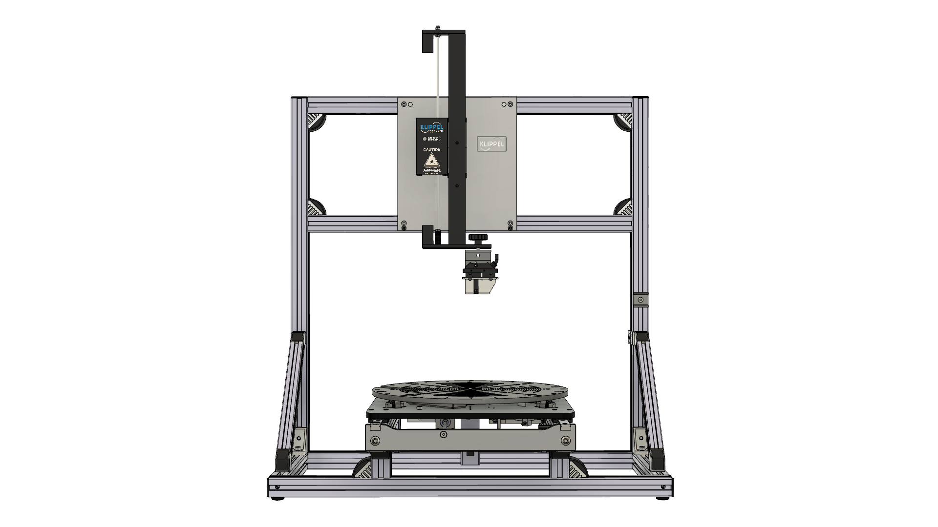
- Use the manual movement of the Motor Control of your SCN Unit to park
the Z-Axis in a central position as shown in the picture.
Laser Sensor Disassembly#
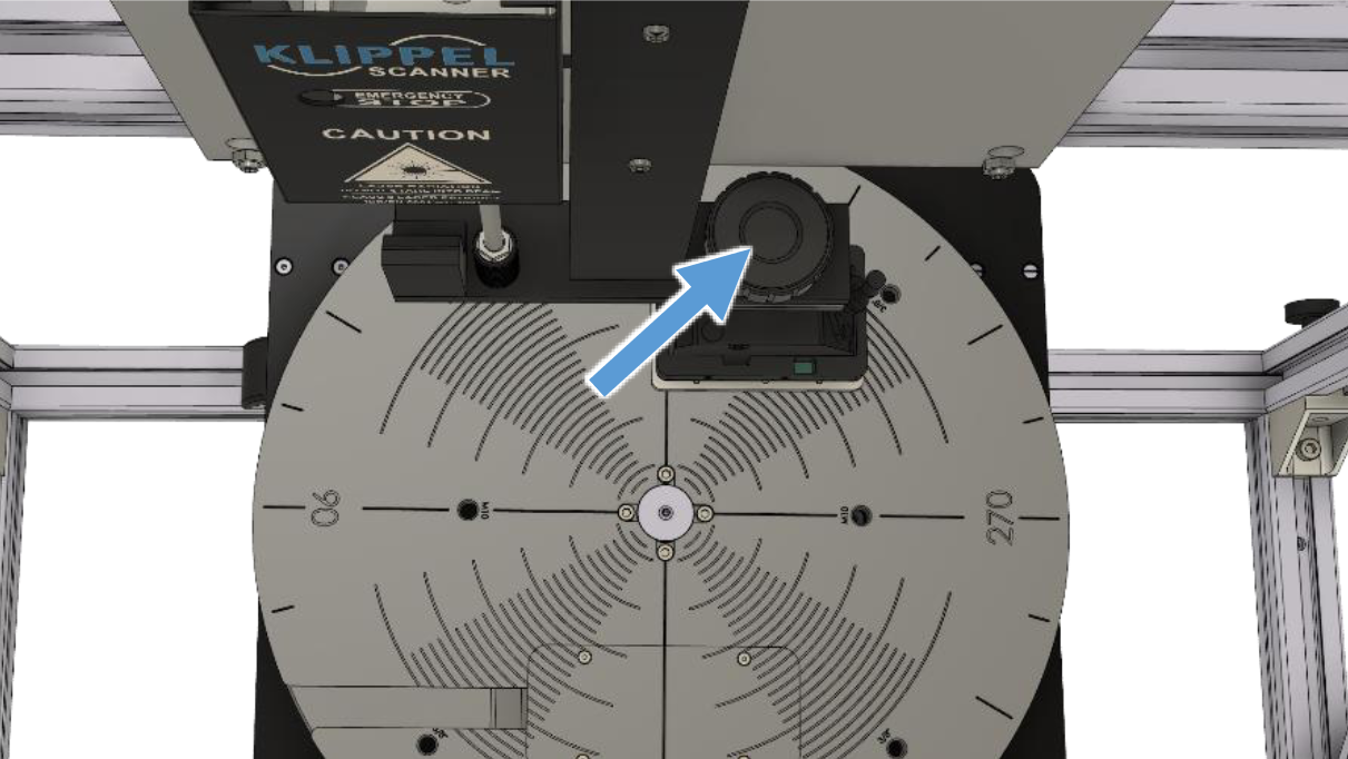
Loosen and remove the knurled screw which mounts the Laser Sensor.
(on some units this may also be a normal screw)
Lower Z-Axis Mounting Block Assembly#
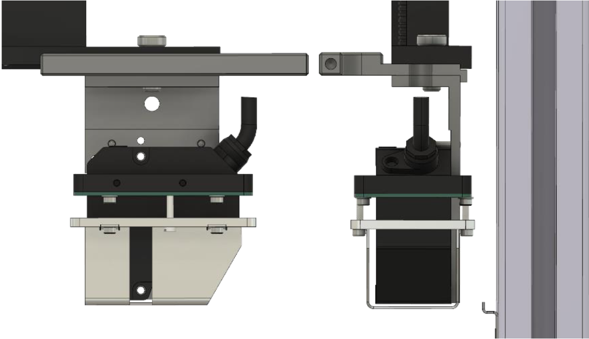
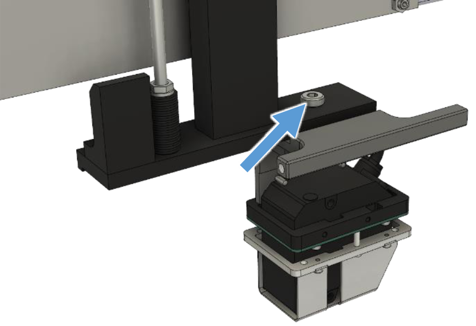
Insert the Lower Z-Axis Mounting Block between the bottom end of the SCN Z-Axis and the Laser Sensor.
Remount the Laser Sensor together with the Mounting Block using the M8x20 low profile screw provided with the Add-On. (Do not fully tighten the screw yet.)
Align the Mounting Block to the back edge of the bottom end of the SCN Z-Axis and align the Laser Sensor to the back edge of the Mounting Block as shown in the upper right picture.
Tighten the M8x20 screw to lock both Mounting Block and Laser Sensor in place.
Upper Z-Axis Mounting Block Disassembly#
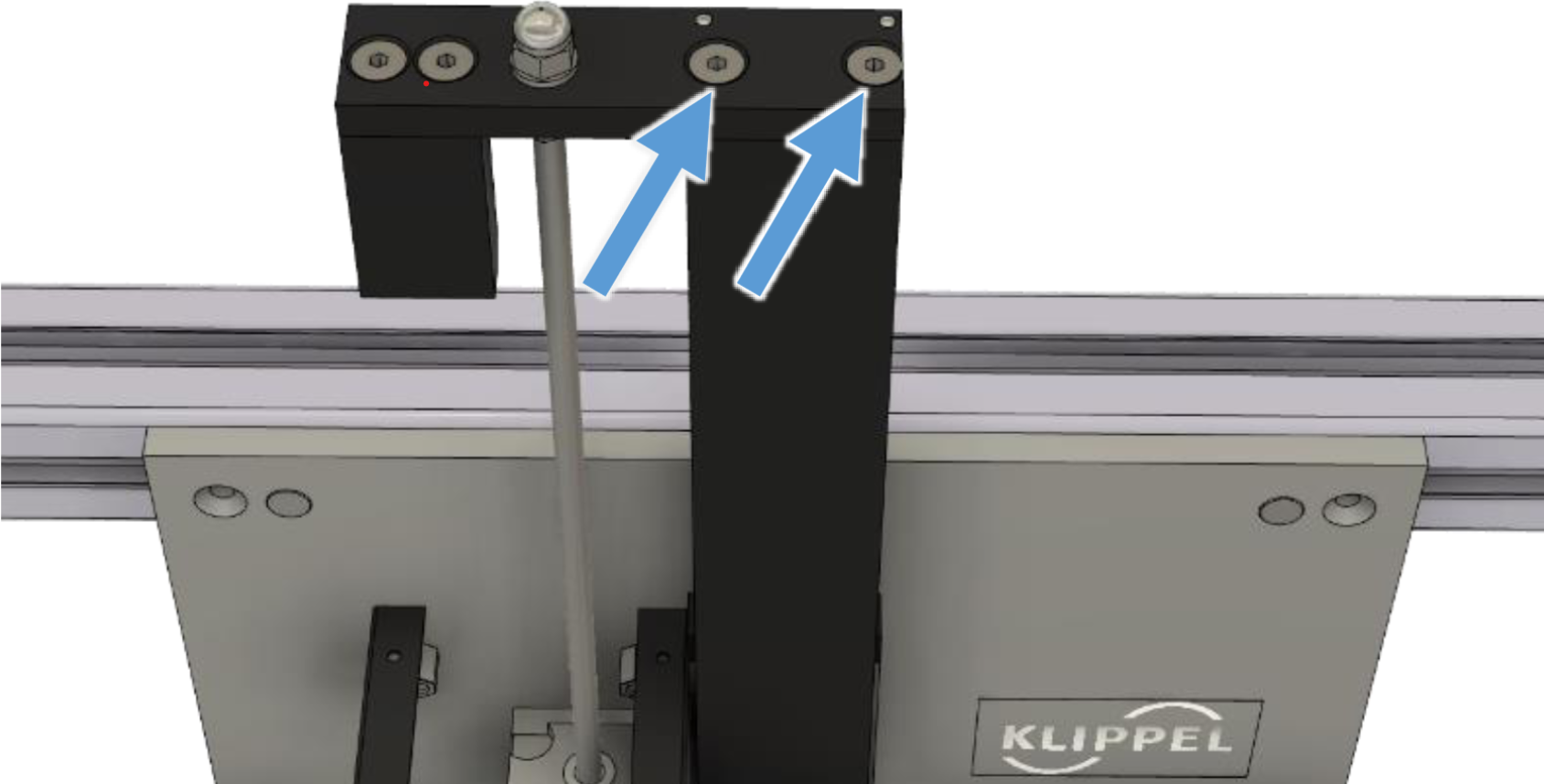
Loosen and remove the two M5x12 countersunk screws at the top end of the SCN Z-Axis.
Upper Z-Axis Mounting Block Assembly#

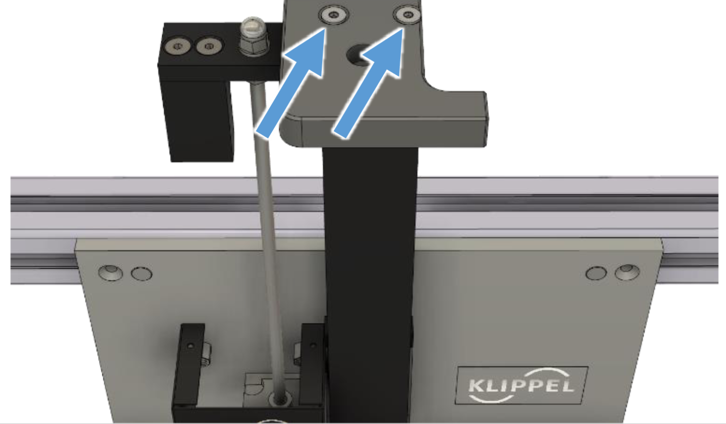
Place the Upper Z-Axis Mounting Block on top of the SCN Z-Axis
Align the back edge of the Mounting Block to the back edge of the Z-Axis as shown in the upper right picture.
Mount the Block using the two M5x35 countersunk screws provided with the Add-On.
Microphone Sensor Arm Upper Assembly#
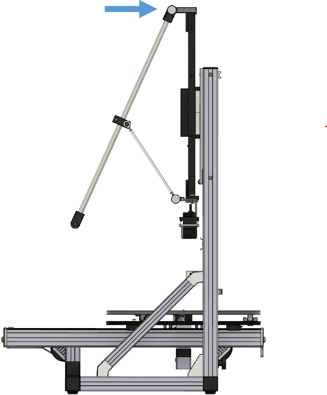
Prepare the Microphone Sensor Arm by removing the packaging from the pre-mounted assembly.
Mount the Microphone Sensor Arm with the integrated knurled screw to the Upper Mounting Block.
Microphone Sensor Arm Lower Assembly#
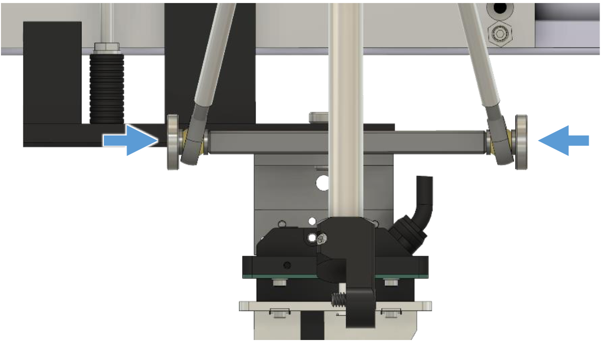
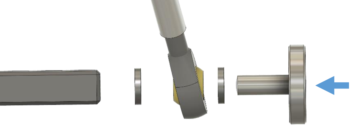
Mount the Support Arms of the Microphone Sensor Arm Assembly to the Lower Mounting Block using the M6x16 knurled screws provided with the Add-On.
Place a M6 washer between the Mounting Block and the Support Arm bearing and another M6 washer between the Support Arm bearing and the knurled screw as shown in the picture.
Microphone Holder Assembly#
Mount the Microphone Holder supplied with your measurement microphone with the UNC ¼” screw and a M6 Washer provided with the Add-On
Cable Assembly#
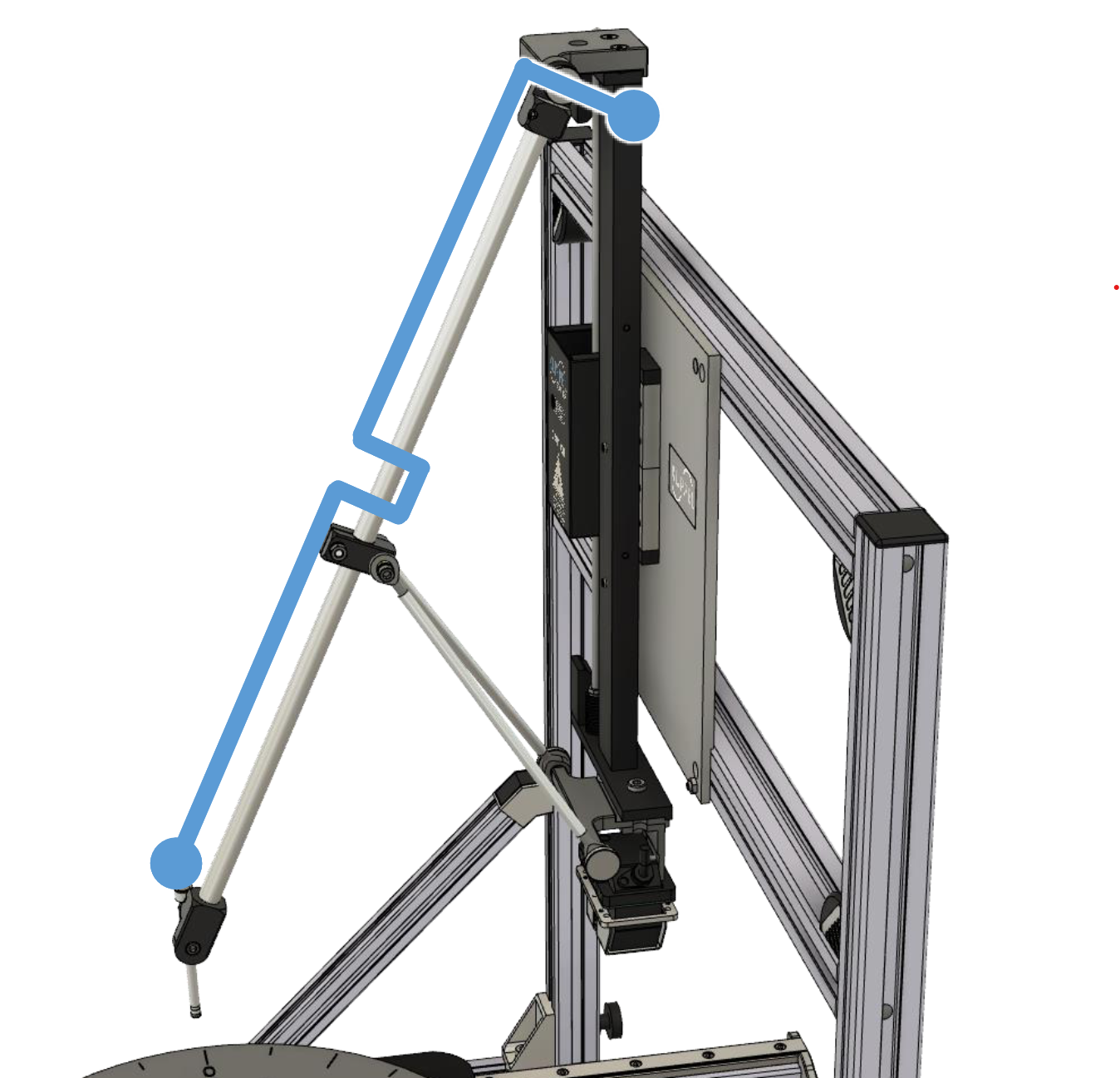
Install your Measurement Microphone in the Holder.
Run the 1m extra thin BNC Cable as shown in the picture with a small loop. Use Cable Clamps to fix the Cable on the Sensor Arm.
Cable Chain Assembly#
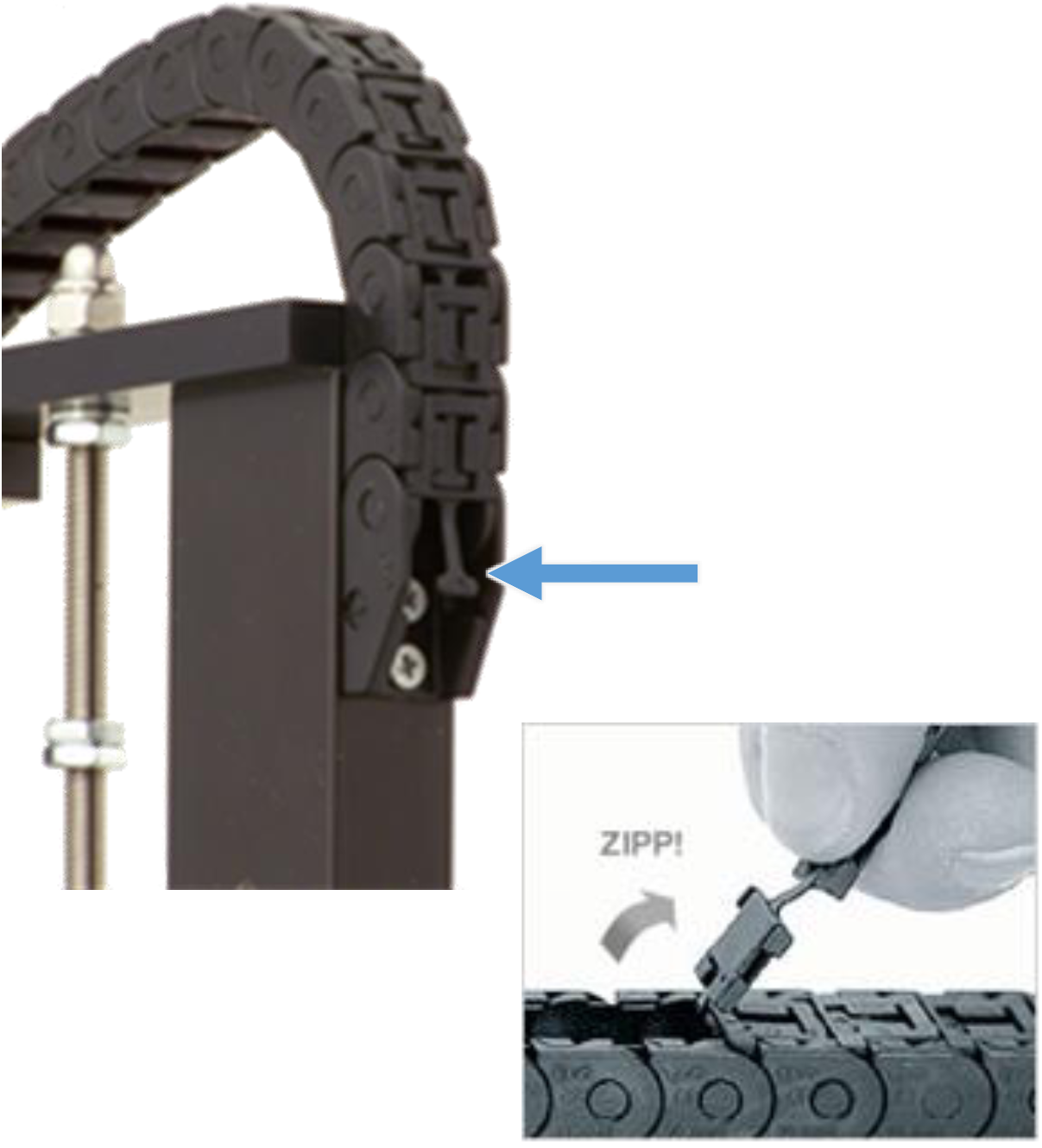
Zip-open the clips of the cable chain on the SCN Z-Axis.
Insert the 2 m extra thin BNC Cable into the cable chain and lock the clips again.
Link both extra thin BNC Cables together with a BNC Coupler.
Link the standard BNC Cable supplied with your mic to the other end of the the 2 m extra thin BNC Cable also using a BNC Coupler.
Baffle assembly#
List of Parts#
Box 1#
Pcs. |
Description |
|---|---|
1 |
Baffle (wood aluminum sandwich) |
2 |
Rotating Feet |
2 |
Stationary Feet |
Bag 1#
Pcs. |
Description |
|---|---|
2 |
Stationary Feet Holder |
8 |
M6x12 screw (ISO 7380-2 in rev. >= 1.2, DIN 912 / ISO 4762 in rev. <= 1.1) |
4 |
M6 washer (only for rev. <= 1.1) |
Mounting instruction for rev. >= 1.2#
Refer to the mounting instructions in chapter Mounting instruction for rev. >= 1.2 for actual SCN Near Field Add-Ons of rev. 1.2 and larger. The latest version with 3D-printed feet.
Refer to the mounting instructions in chapter Mounting instruction for rev. 1.0 - 1.1 for earlier SCN Near Field Add-Ons of rev. 1.0 and 1.1.
Step 22#
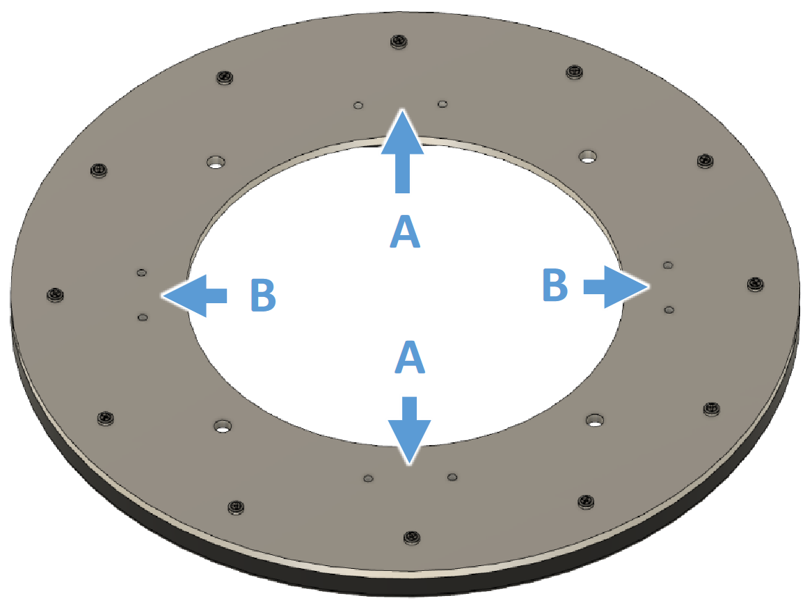
Notice the different distance between the M6 threaded holes (A - larger / B - smaller) on the bottom of the baffle.
Step 23 - 24 (rev. >= 1.2)#
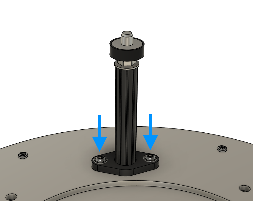
Place a Rotating Feet on location A and mount it using two M6x12 screws.
Repeat on the other location A.
Step 25 - 26 (rev. >= 1.2)#
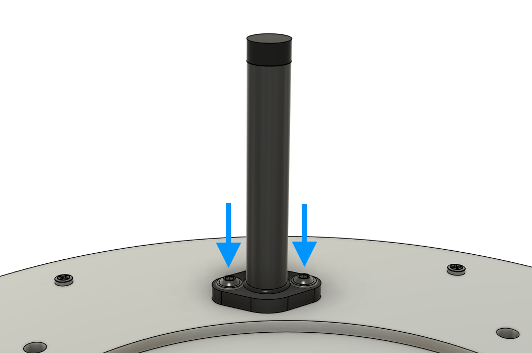
Place a Stationary Feet on location B and mount it using two M6x12 screws.
Repeat on the other location B.
Step 27 - 29 is not needed in rev. >= 1.2.
Step 30 (rev. >= 1.2)#
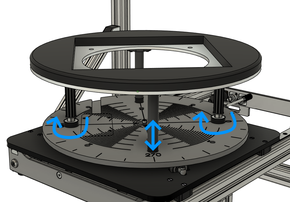
The Baffle assembly is finished! Mount it on the SCN by screwing the Rotating Feet into the turntable at the locations 0 and 180°. Screw them in symmetrically to prevent their threads from damage! Use the rubber feet to align the baffle horizontal and avoid rattling.
Proceed the setup with the Room setup recommendations.
Mounting instruction for rev. 1.0 - 1.1#
Step 22#
Notice the different distance between the M6 threaded holes (A - larger / B - smaller) on the bottom of the baffle.
Step 23 - 24 (rev. 1.0 - 1.1)#
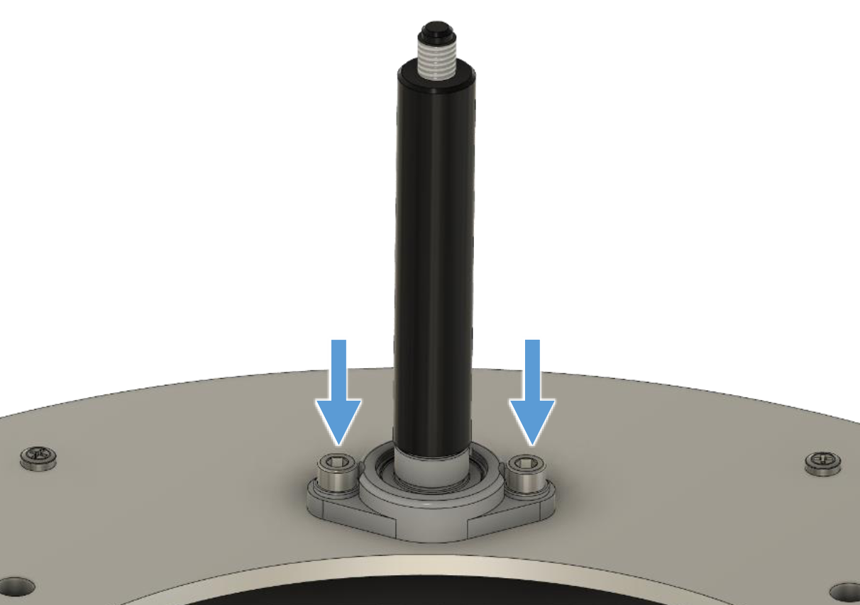
Place a Rotating Feet on location A and mount it using two M6 washers and M6x12 screws.
Repeat on the other location A.
Step 25 - 26 (rev. 1.0 - 1.1)#
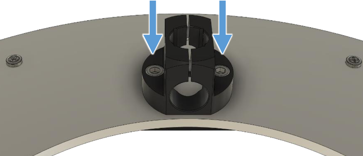
Place a Stationary Feet Holder on location B and mount it using two M6x12 screws.
Repeat on the other location B.
Step 27 - 28 (rev. 1.0 - 1.1)#
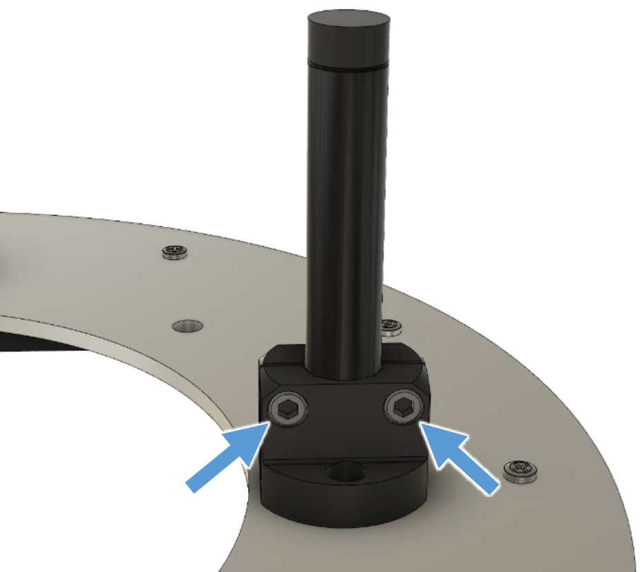
Insert a Stationary Feet into the Holder with the rubber tip pointing away from the baffle and tighten the screws of the Holder.
Repeat on the other location B.
Step 29 (rev. 1.0 - 1.1)#
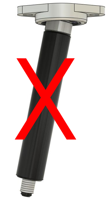
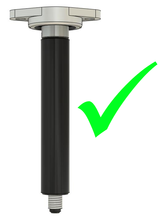
Bring the Rotating Feet in a perpendicular position before mounting to protect their threads!
Step 30 (rev. 1.0 - 1.1)#
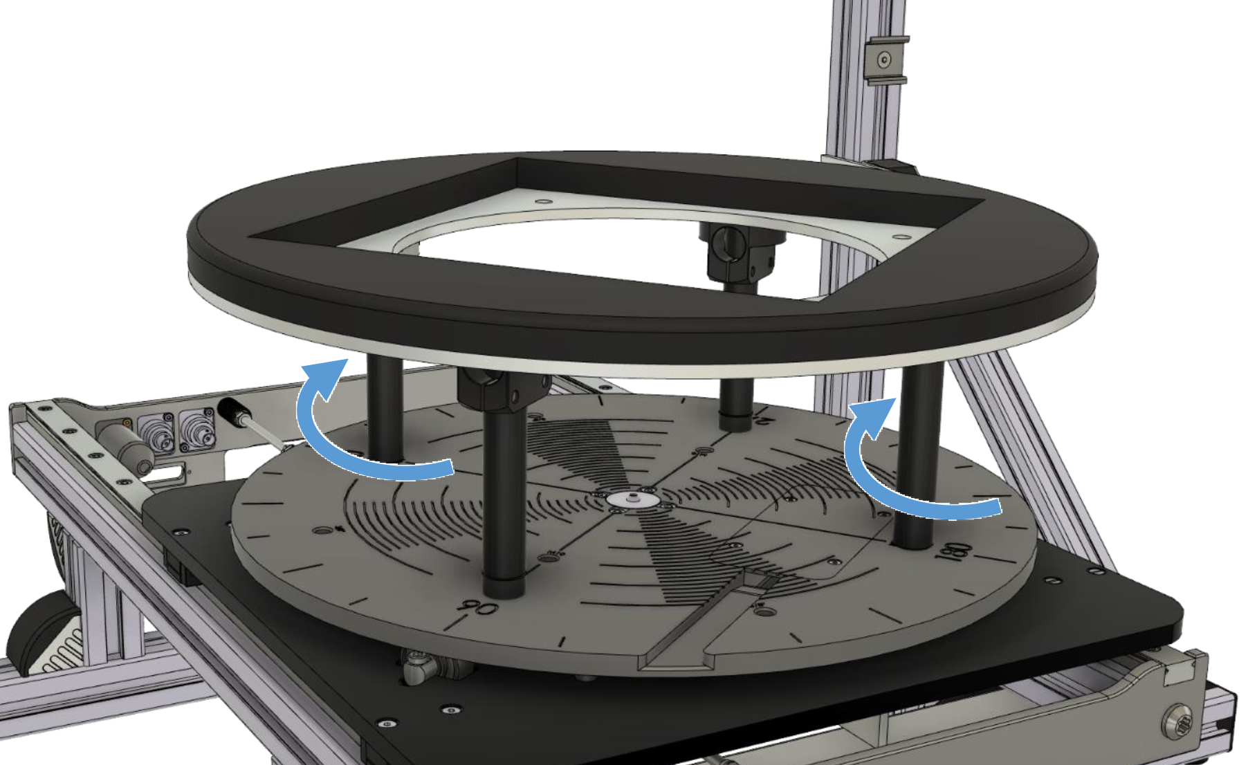
The Baffle assembly is finished! Mount it on the SCN by screwing the Rotating Feet into the turntable at the locations 0 and 180°. Screw them in symmetrically to prevent their threads from damage! Use the rubber feet to align the baffle horizontal and avoid rattling.
Note
Rev. >= 1.2 feet are available as replacement parts for rev. 1.0 - 1.1 SCN Near Field Add-Ons.
Room setup recommendations#
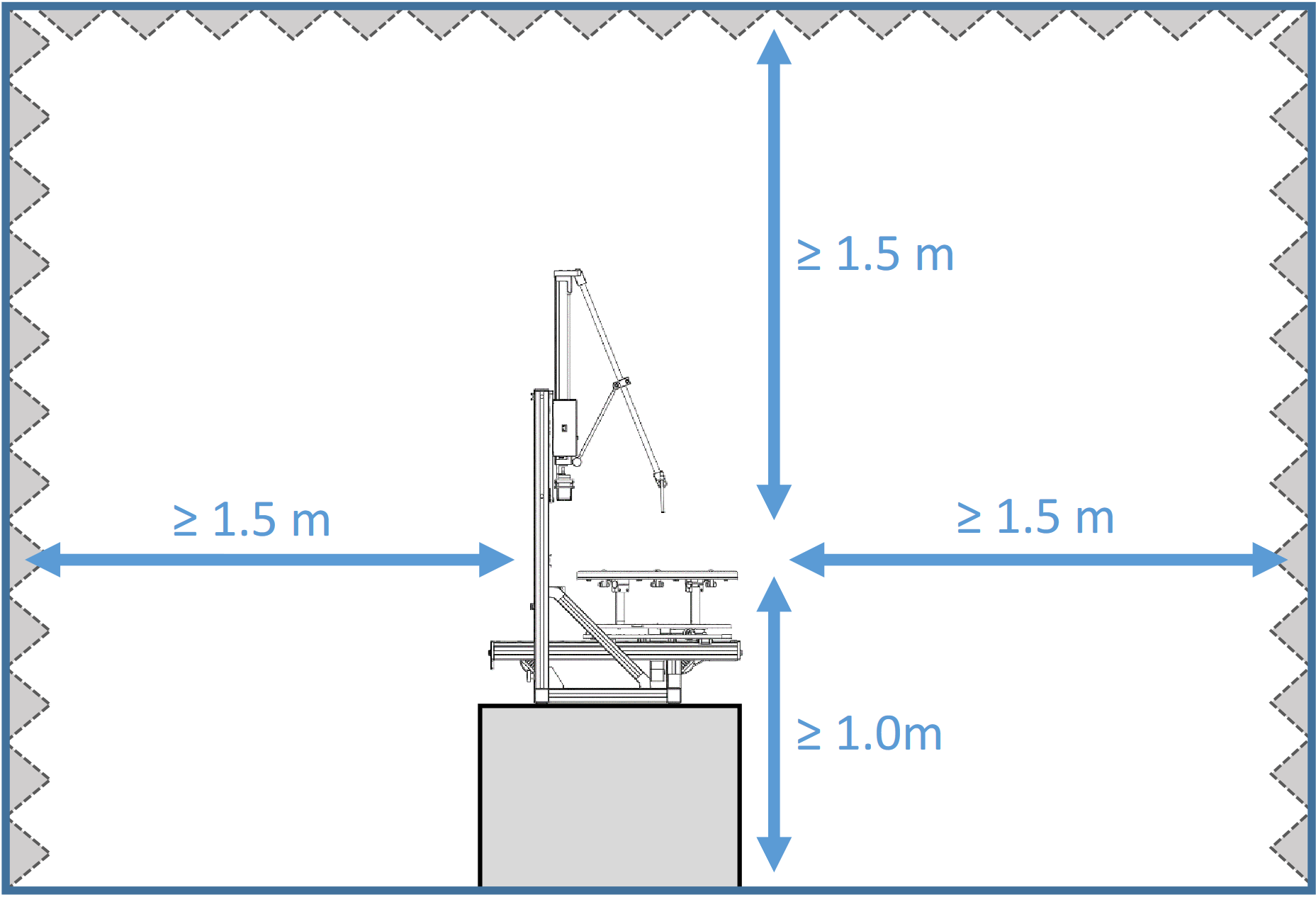
It is recommended to setup the SCN with the Near Field Add-On at an elevated position in the center of a room providing maximum distance to the room boundaries (walls, floor, ceiling). A minimum distance of 1.5 m to all walls and ceiling and 1 m to the floor is recommended. The ideal setup location for the SCN Near Field Add-On is on a small table or 19” rack in the center of a room with a size of at least 3m x 3m x 2.5m.
If a smaller room has to be used, acoustic absorbers can be applied to walls and ceiling to increase measurement precision. Relatively thin absorbers with a thickness of 50mm and an absorption coefficient larger than 0.5 from 500 Hz up are sufficient.
A smaller reflection-free distance without additional absorbers can also be used if only very small DUTs (< 50 mm) are measured.
Adjustments on first-time setup#
The SCN Near Field Add-on is designed for maximum compatibility with all KLIPPEL SCN revisions. The Microphone Sensor Arm is delivered in a partially assembled configuration which is directly compatible with most SCN units. On some early model SCNs additional adjustments or small modifications may be necessary.
During the setup of a measurement the microphone is positioned over the large SCN Calibration Cone in order to setup an origin point by adjusting the lower Support Arms. When the adjustment range of these Support Arms is insufficient to reach the Calibration Cone at the intended r-axis position further adjustment is necessary:
Step 31#
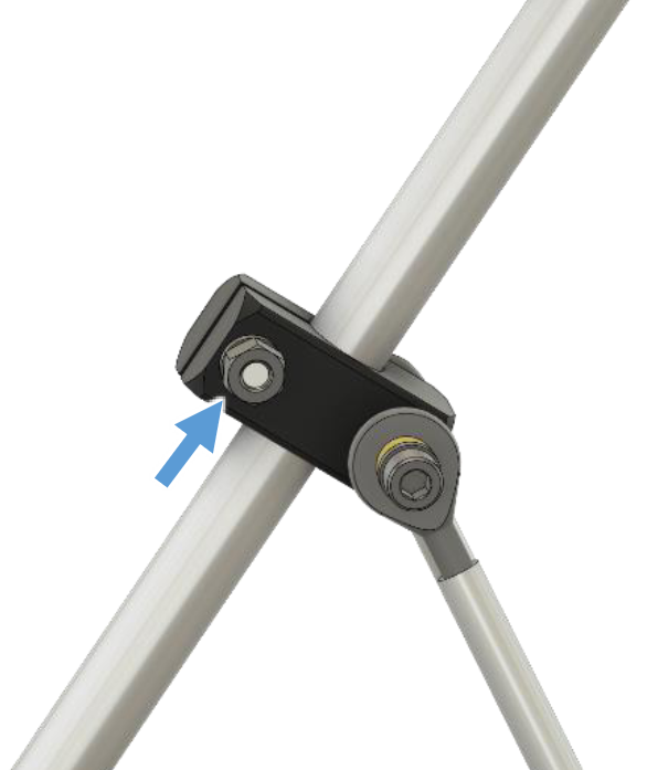
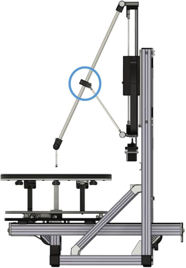
Loosen the upper M6 screw of the joint block which connects the lowe Support Arms to the main Sensor Arm.
Step 32 - 33#
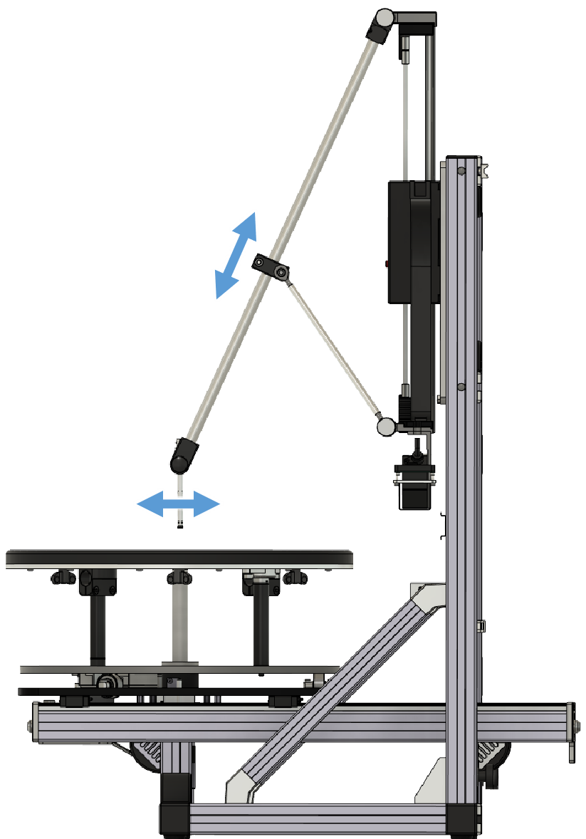
Reposition the joint block on the Sensor Arm so that the Calibration Con can be reached.
Tighten the upper M6 screw on the joint block again.
