
Example Speaker#
Dear KLIPPEL-User, the example speaker shall help you to get a smooth and efficient start with the KLIPPEL system. This manual is addressed to new customers with no or limited knowledge of KLIPPEL measurement technology.
Note
The example database included in dB-Lab contains pre-measured data of a reference example speaker (golden reference speaker) similar to your individual example speaker. This database is automatically opened after the first installation of dB-Lab. You may open it at any time by selecting the menu dB-Lab/Project/Select Database…/Database/Examples… Detailed information is available in the dB-Lab manual.
To browse the results of your individual example speaker database:
Download the database of your example speaker from your Klippel User Site.
Double-click the *.kdbx file to open with dB‐Lab software, read this Example Speaker Manual to understand the measurements and get familiar with first own measurements.
If there is no individual example speaker database available, you may also use the example database included in dB-Lab.
Overview#
The goals of this manual are:
Help with executing the first measurements.
Check measurement setup by comparing your results with pre‐measured data from Klippel.
Get an overview of the wide range of Klippel measurements, according to IEC-60268-21 and IEC-60268-22. (This section will be added soon. An updated version of the example speaker database and the related manual will be available.)
See also
This document provides information regarding the measurements and templates included in the Example Speaker Database. Detailed information about the use of the software dB-Lab is available in the dB-Lab manual. The free KLIPPEL online training provides the opportunity to get a comprehensive knowledge base of loudspeaker theory, modelling and measurement techniques.
All Klippel R&D measurement systems are delivered with an Example Speaker which was measured individually using the Klippel Quality Control (QC) System. More detailed measurements were done using a Golden Example Speaker with almost similar properties. All measurement results of your example speaker and the corresponding golden Example Speaker are provided together in your personalized Example Speaker Database.
This manual and the corresponding database are divided into:
Starter Measurements for system check and starting with Klippel.
Advanced Measurements according to the mentioned standards.
Starter Measurements#
The goal of the Starter-Measurements are
A guided introduction into the most common Klippel-measurement-modules,
And a basic system check.
Preparing Measurement Setup#
This section gives an overview of how to set up the measurement system. The KA3 signal configuration has to be configured in accordance with the physical cable configuration. The two most common setups are presented.
The first schematic presents the setup using the KA3 internal Amplifier-Card.
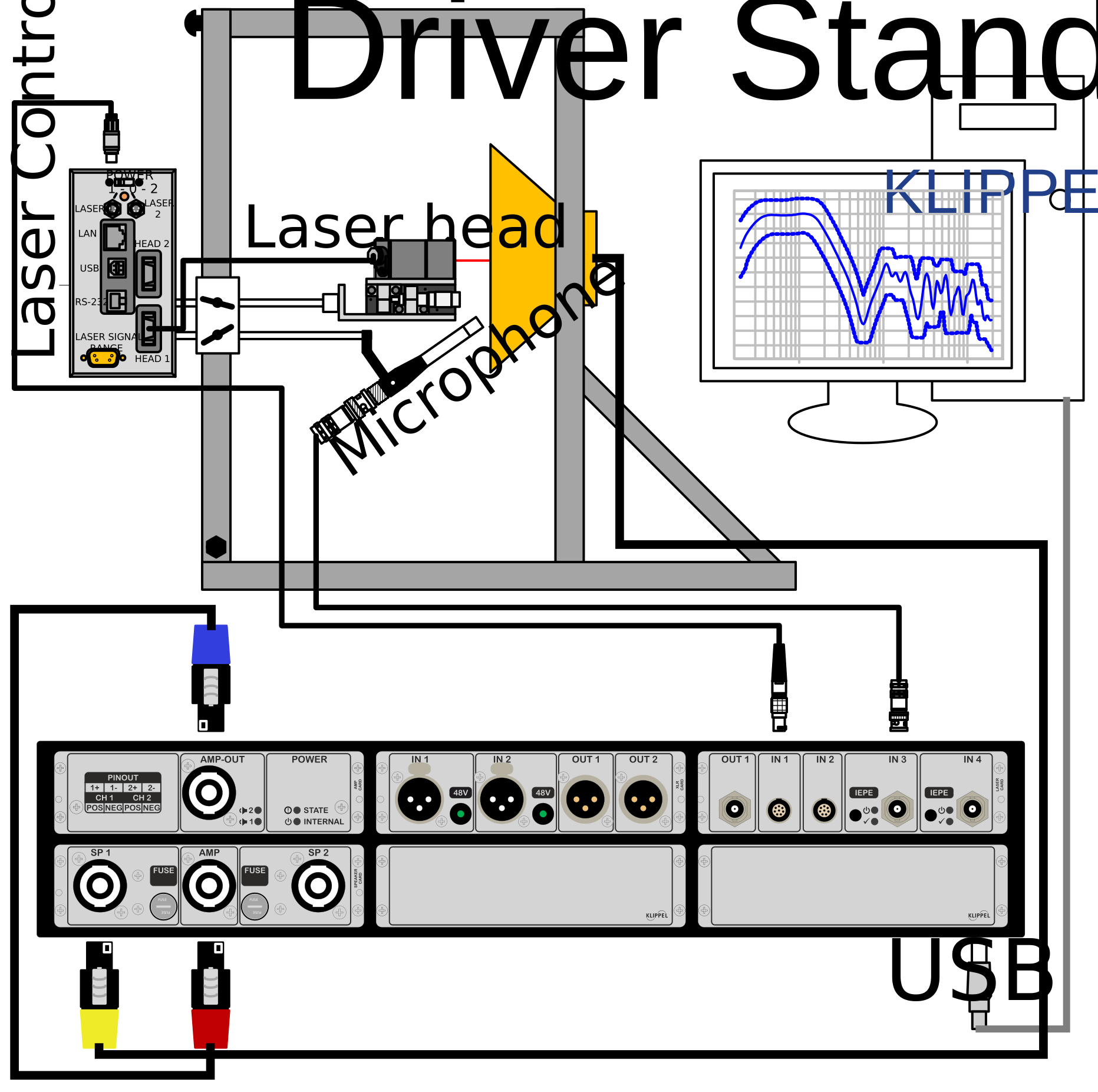
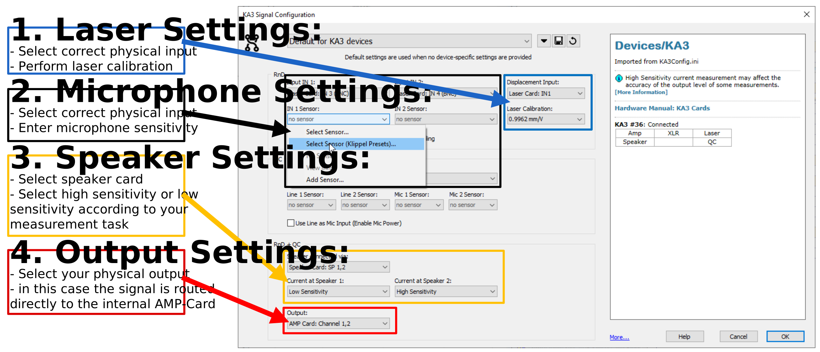
Note
The maximal output voltage of the KA3 Amplifier-Card is limited to 20 Vpeak. It is recommended using an external amplifier if more voltage is required.
The second schematic shows the setup with an external amplifier.
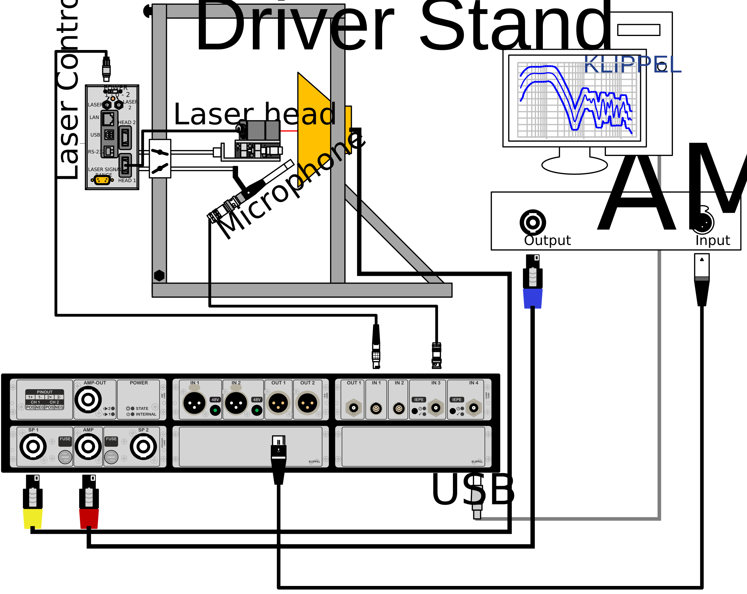
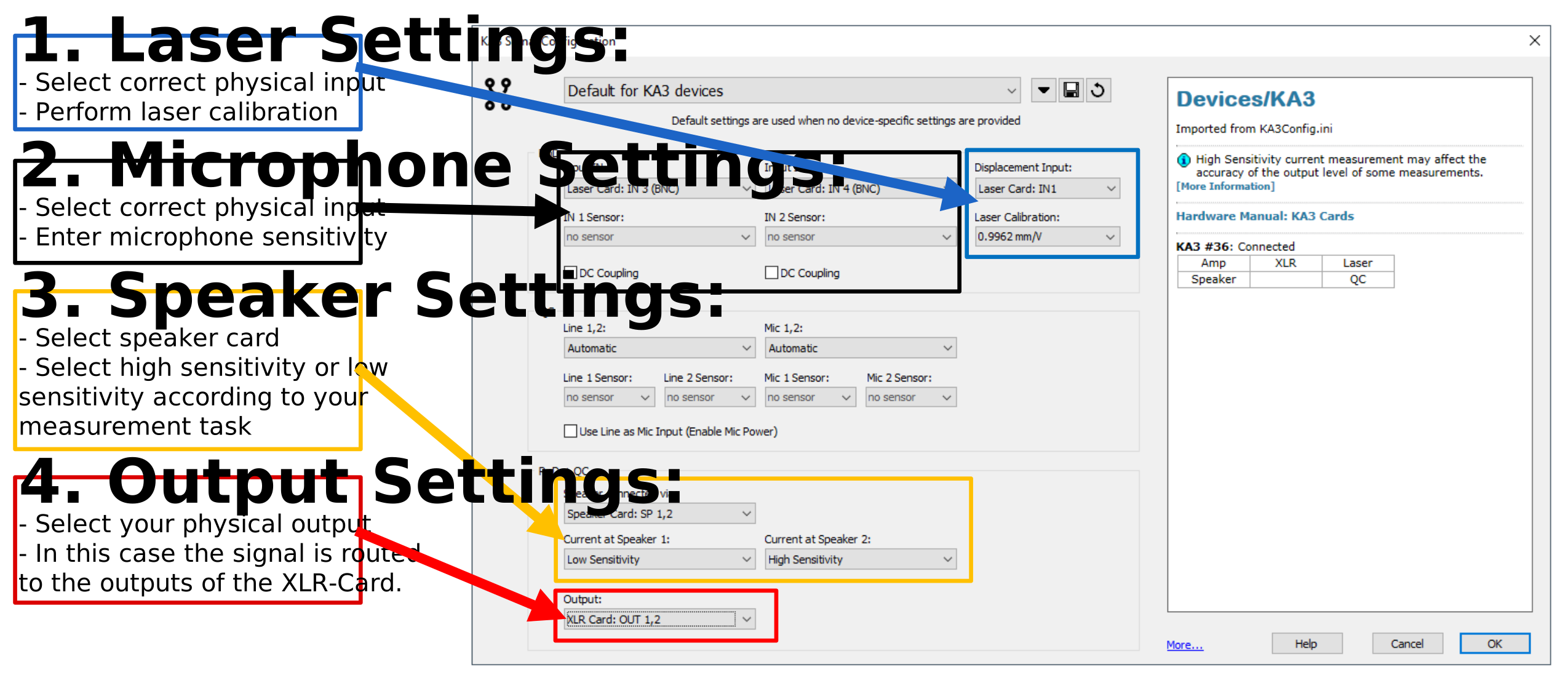
The KA3 Signal Configuration is stored in the currently used dB-Lab installation and will be used for all measurements performed with this software. In case you perform the measuremnet on another PC, you need to readjust the settings.
See also
With dB-Lab 212 major improvements in the signal configuration was implemented. Detailed information about the KA3 Signal Configuration is available in the manual hardware, in section KA3 Signal Configuration.
More detailed information about different hardware options and measurement settings is available in the hardware manual.
Performing Starter-Measurements#
The best way to start with Klippel, is to perform the starter measurements with the delivered Example Speaker. Therefore, a KA3, laser displacement sensor, microphone and licenses for LPM, LSI3, DIS and TRF are required. If one of the listed license is not included in your system, please contact sales@klippel.de to get a trial license or skip the measurements. Performing every measurement and checking the results will help you to check the measurement setup.
Fast Large Signal Identification (FLSI)#
The Fast Large Signal Identification (FLSI) is a parameter measurement module comprising small and large signal parameter measurement. Hardware setup is identical to LPM and LSI3. Please follow the instructions below. If you don’t have a FLSI license, please skip this measurement and continue with LPM. You may contact sales@klippel.de to get a trial license.
Linear Parameter Measurement (LPM)#
With the Linear Parameter measurement (LPM), the well-known Thiele/Small parameters are measured. For more details check out the LPM manual.
Target#
Wile performing this measurement, you can check your laser, voltage and the high sensitive current sensor. If the results are deviating significantly from the example data of the golden reference unit, you need to check your hardware and KA3 signal configuration settings. In this case, please check out section prepare measurement.
How to start the measurement?#
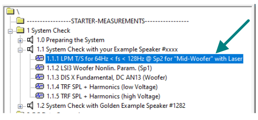
Select the LPM template in the object 1.1 System Check with your Example Speaker #xxxx.
Open the KA3 Signal Configuration and select High Sensitive (Low Current) for current sensor at speaker 2.
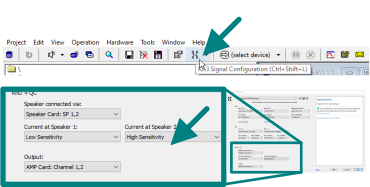
Start the operation by clicking on
 (Run-button).
Results#
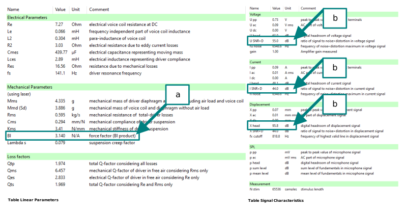
Compare the results presented in the table linear parameters with the results of the golden reference speaker. Bl is the most significant value for this comparison. The deviation should be less than 5%.
Besides this, we recommend to check the SNR+D, shown in the table signal characteristics. This should be above 20 dB. Usually we expect values in the range of 30-40 dB.
See also
If SNR+D is poor, increase the number of averaging. This will reduce the noise floor. More detailed information are available in Application Note AN-25.
Large Signal Identification (LSI3)#
The Large Signal Identification (LSI3) identifies the nonlinear properties of a loudspeaker. Typical curves like Bl(x) and Kms(x) are displayed. For more details check out the LSI manual.
Target#
While performing this measurement, you can check your laser, voltage and low sensitive current sensor. If the results are deviating significantly from the example data of the golden reference unit, you need to check your hardware and KA3 signal configuration settings. In this case, please check out section prepare measurement
How to start the measurement?#
Select the LSI3 template in the object 1.1 System Check with your Example Speaker #xxxx.
Import the linear parameters from the previous done LPM measurement into the LSI3.
Open the KA3 Signal Configuration and select Default (High Current) for current sensor at speaker 1.
Start the operation by clicking on
(Run-button).
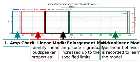
The LSI excecutes an automated measurement procedure of 4 parts. The total measurement duration is about several minutes. During this process, the stimulus is adjusted automatically for getting optimal measurement conditions.
Results#
The LSI3 is showing the well known nonlinear curves of Bl(x), Kms(x) and Le(x).

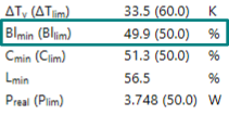
If the results are looking strange, check the limiting parameters in the measuremnet. This data is available in the table states. Sufficient excursion is necessary to get data for a good fitting. In the example below, Bllim is the limiting parameter.
Warning
Temperature and power are only protection related limits. Bllim and Clim are limiting parameters for optimal fitting.
Distortion Measurement (DIS)#
The Distortion Measurement module (DIS) is a comprehensive tool to analyze the root cause of distortion produced by a loudspeaker. The DIS performs a series of steady-state measurements by using a singleor two-tone excitation signal varied in frequency and voltage. For more details check out the DIS manual.
How to start the measurement?#
Select the DIS-template in the object 1.1 System Check with your Example Speaker #xxxx. The template Focuses on the fundamental displacement behavior and the dynamically produced DC component.
Adjust the stimulus properties. The maximum in the amplitude should be derived from the LSI3 and equals the rounded voltage, needed For getting Xprot.
Start the operation by clicking on
(Run-button).
Results#
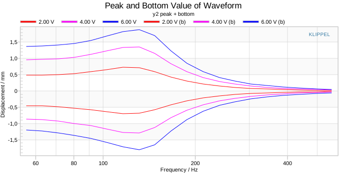
Peak and Bottom Value of Waveform provides a quick overview about the measurement and shows the highest and lowest displacement values, measured for each voltage and frequency step.
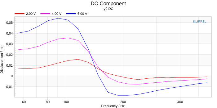
DC component reveals the offset of the speaker membrane relatively to its rest position.
Transfer Function Measurement (TRF)#
The aim of the Transfer Function Measurement module (TRF) is to measure two signals (e.g. microphone and terminal voltage) to calculate the corresponding transfer functions, harmonic and impulsive distortion. For more details check out the TRF manual.
Target#
While performing this measurement, you can check your microphone. If the results are deviating significantly from the example data of the golden reference unit, you need to check your hardware and KA3 signal configuration settings. In this case, please check out section prepare measurement
Setup the hardware in accordance to one of the presented setups. Check the microphone and its settings. For the presented data the hardware setup with KA3 Amplifier-card was used.
Templates#
For performing a TRF measurement, two different templates are available in the object 1.1 System Check with your Example Speaker #xxxx.
The template low voltage has the target to measure the fundamental transfer behaviour in the linear domain. Additional to this, the harmonic distortion is measured.
The template high voltage can be used to measure the harmonic distortion at higher levels. The higher level, stresses the loudspeaker and we can assume much higher distortion. At this level, the impulsive distortion should also be checked.
How to start the measurement?#
Check your microphone connection and settings as described above.
Select one of the two TRF templates.
Start the operation by clicking on
(Run-button).
Results#
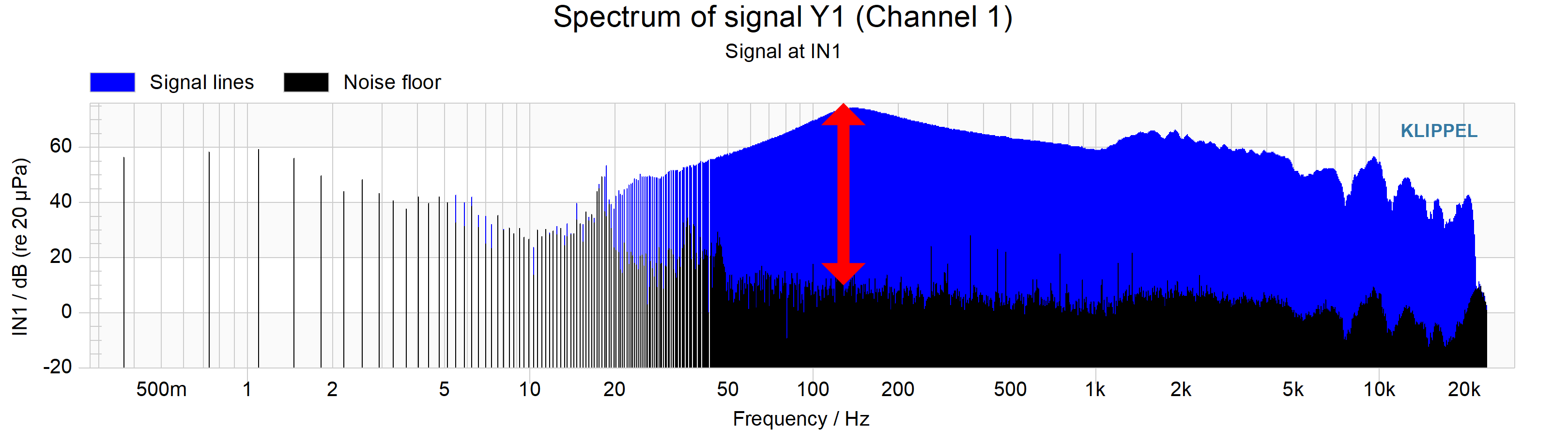
Before checking the results, the SNR in the microphone signal should be checked.
Resons for bad SNR#
Microphone is not connected correctly. In this case only noise signals are measured. Viewing the y1(t) Input Waveform window will help to check this.
Missing power supply for IEPE or phantom powered microphones. In this case the measured signal Y1 is very low and noisy but a transfer function could be fitted.
Microphone is not located in the near field of the DUT. A higher ambient noise is detected which may corrupt the measurement.
QC-Data and Starter Measurements#
The deviation between the delivered example speaker and the golden reference can be investigated by viewing the QC measurement results.
The KLIPPEL QC environment is designed to test and classify speakers using limits. The so-called golden unit defines the reference speaker. Every measured DUT is compared with this golden unit. The DUT will pass the measurement if the deviation to the golden unit is below an desired threshold. The golden unit is not in every case the optimal loudspeaker but describes a desired reference behaviour.
Interpreting QC-Results#
The single value results of the QC measurement are presented in the window Summary. The first table presents the deviation in the measured results referred to the golden example speaker. green parameters are inside the limit tolerance and red values cross the desired limits. Grey parameters are not measured. Detailed information is available in the tables below. These results are structured by the performed QC tasks:
Impedance Task (IMP)#
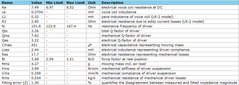
The impedance task (IMP) is designed to measure the linear impedance of a DUT. In this case, the impedance task was performed using an additional laser. This provides the option to estimate also the linear mechanical parameters of the DUT. The resulting linear parameter should be nearly identical to the linear parameters measured by the LPM measurement.
See also
For more details check out the manual impedance task.
Motor Suspension Check (MSC)#
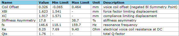
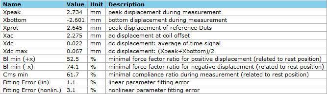
The motor suspension check (MSC) investigates the large signal behaviour of the DUT. One main result is the coil offset. This is a meaningful parameter to rate the quality of a DUT. Several results of the MSC are comparable to the results of the LSI, under the condition of comparable maximal excitation. To ensure this, \(x_{\text{peak}}\) in the MSC should equal \(x_{\text{prot}}\) in the LSI.
See also
For more details check out the manual MSC task.
Conclusion of the Starter Measurements#
After passing all described preparation steps and performing the starter measurements, the KLIPPEL measurement system should be well installed and calibrated for further measurements. Go through the following checklist to ensure this:
All measurements from the object 1.1 System Check with your Example Speaker #xxxx is done with the delivered example speaker.
The comparison of the measurement results and the results of the Golden Example Speaker reveal no conspicuous deviation.
The linear parameters provided by the QC operation (2.2 Data from your Example Speaker) are equal to the measured linear parameters of the LPM measurement, done at your side (1.1.1 LPM T/S for 64Hz < fs < 128Hz @ Sp2 for “Mid-Woofer” with Laser).
To ensure that all measurement results are reliable and not corrupted by a missing or wrong sensor calibration, we highly recommend checking the system accuracy frequently. Therefore, a lab reference speaker should be used. This could be the delivered example speaker or any other well-known sample. Running just one LPM measurement and comparing the Bl value ensures that the KA3 with its voltage and current sensors and the external laser sensor performing correctly.
Advanced Measurements#
KLIPPEL provides a wide range of software modules and hardware accessories which allows performing different measurement tasks. In the previous chapter only common measurements were shown with a focus on how to perform the measurements and check accuracy. More sophisticated measurements and their results are presented in this chapter.
Relevant loudspeaker measurement tasks are defined in IEC 60268-21 and IEC 60268-22. The aim of this chapter is to provide an overview of available KLIPPEL measurement methods according to these standards. Thereby the focus is on illustrating measurement tasks and showing the measurement results of the example speaker. Details about how to set up and run such measurements are available in the corresponding manuals and not part of this document.
For these measurements, further hardware and software are required. A list of required items is available in the corresponding sections.
Acoustical Measurements#
The standard IEC 60268-21 focuses on acoustical output-based measurements. All measurement presented in this section was performed by using the KLIPPEL Workbench. This hardware allows to perform acoustical measurements in the near field of an transducers in a small round baffle.
Directional Characteristics [IEC 60268-21,20]#
Section 20 of IEC 60268-21 defines conditions for measuring the directional characteristics of an audio device. The KLIPPEL Workbench hardware is able to move the measurement microphone in the z-direction and the DUT in the r and phi direction. The Robotics software controls the KLIPPEL Workbench hardware and performs fully automated a set of acoustical measurements on a half sphere in the near field of the DUT.
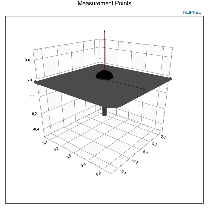
The measurement object 3.4 Directional Characteristics [20] contains the results of a scan of the whole half-sphere above the baffle.
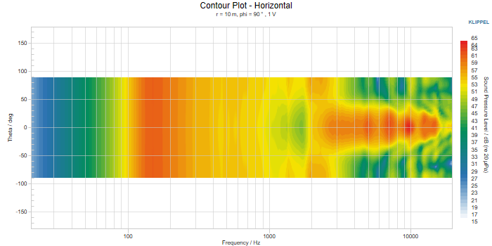
The results of each measurement are stored in a data container which is available as operation in dB-Lab. To save memory, the data container is not fully included in the delivered example-speaker database. By running the field identification, the measured sound radiation is analyzed and a set of holographic coefficients are calculated to describe the sound field of the DUT. The window Near Field SPL Response (right picture below) is showing the measured SPL response as well as the fitted SPL response which is the result of the holographic field identification. Subtracting the room reflections leads to the radiated SPL response.
Outgoing from the calculated holographic coefficients the visualization operation presents several curves and graphs. The presented curves are only valid for certain frequencies or points in space. Details are presented in the subtitle of each chart e.g., Magnitude and Phase for 10 m distance on axis displayed in the picture below.
Requirements#
Hardware#
KA3 including Speaker, Laser and XLR card.
KLIPPEL Workbench
1/4 inch measurement microphone (GRAS 40PP-10 is recommended)
Either an external amplifier or the Amplifier-card is required.
Software#
Workbench software package for acoustical analysis.
Electrical and Mechanical Measurements#
The standard IEC 60268-22 focuses on electrical and mechanical measurements. All measurement presented in this section was performed by using the KLIPPEL SCN hardware.
Vibration of the Radiator Surface#
Section 19 of standard IEC 60268-21 defines conditions for measuring vibrating surfaces of loudspeakers using laser vibrometers. The SCN performs a fully automated measurement of the vibrating loudspeaker surface.
The vibration pattern of the measured loudspeaker can be investigated directly in the scanner software. The software presents the measured data in 3 pages. The first page labeled with Animation, shows per default the animated motion for a selected frequency and the Total Acceleration Level on the bottom.
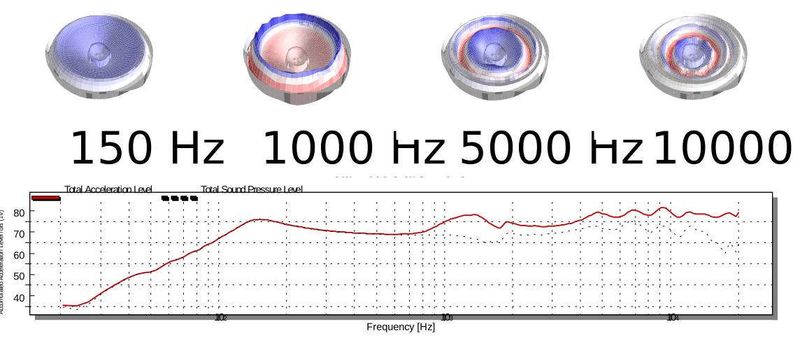
The frequency can be adjusted by clicking on the Total Acceleration chart or by adjusting the value in the control panel on the right side. The second page Radiation Analysis provides useful insights about 3D sound radiation. Outgoing from the vibration data, the 3D sound radiation is approximated and can be investigated at different angles. A contour plot is available (see the picture below).
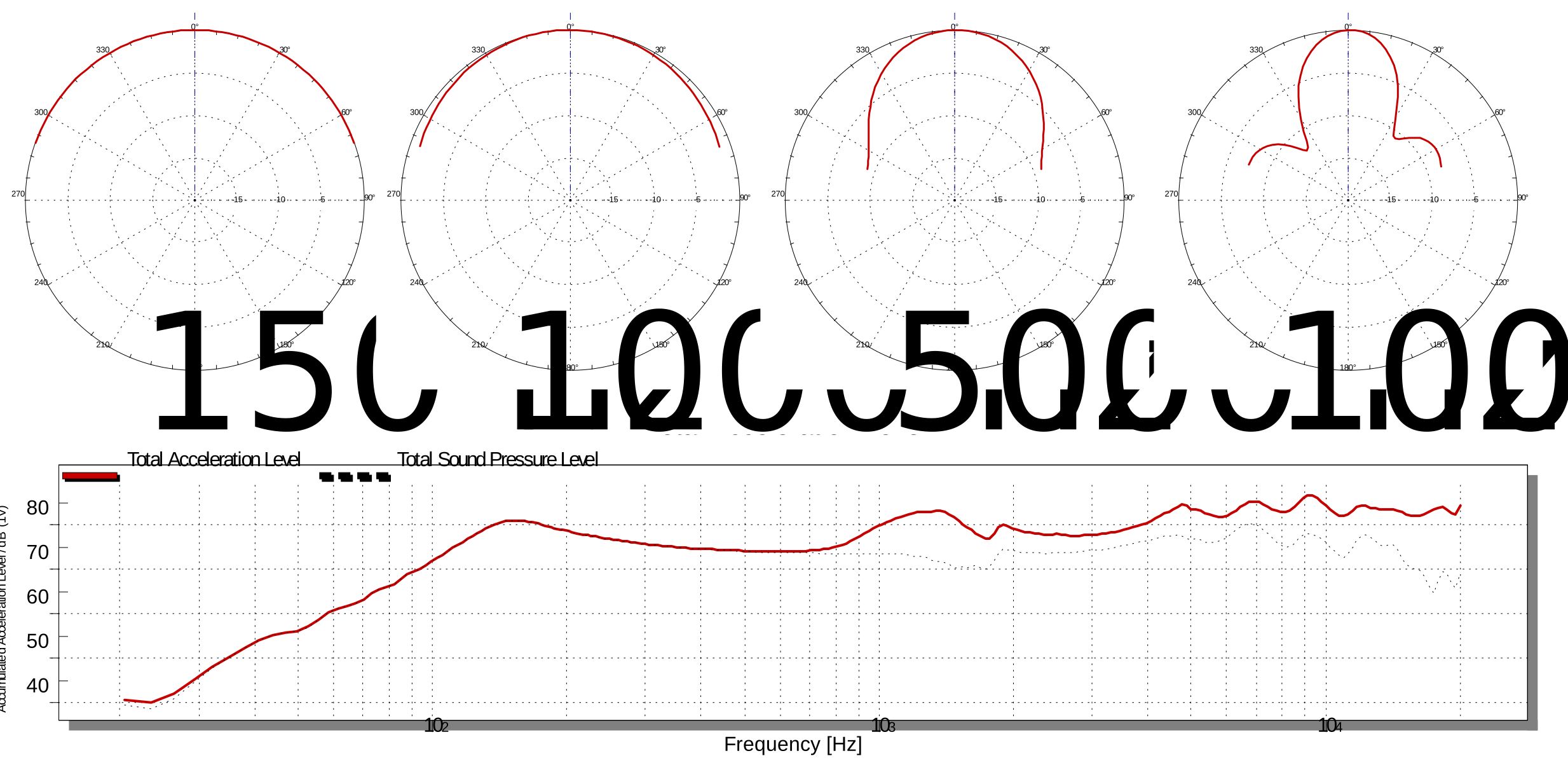
The investigated frequency can be adjusted similarly to the first page. The diagram Total Acceleration Level on the bottom shows the total acceleration as well as the total sound pressure level, valid for the selected radiation angle. The last page Cross-section View presents the displacement motion of the cross-section adjusted in the centre-right diagram on page Radiation Analysis. The diagram on the bottom presents the displacement transfer function of the selected point in cross-section view.
The scanning software contains tools to calculate Sd and sound power. All results can be exported to dB-Lab.
Requirements#
Hardware#
KA3 including Speaker, Laser and XLR card.
KLIPPEL Workbench
1/4 inch measurement microphone (GRAS 40PP-10 is recommended)
Either an external amplifier or the Amplifier-card is required.
Software#
Workbench software package for mechanical analysis.
