
SYN – External Synchronization#
SYN - Tutorial#
Overview#
The External Synchronization (SYN) is an add-on for the QC end-of-line testing framework of the Klippel Analyzer System.
The SYN module provides the possibility to trigger a measurement/analysis via the input signal. A synchronization signal is played back via the complete measurement channel (e.g., playback audio device, amplifier, DSP, loudspeaker, microphone, capture audio device). The SYN module is able to detect the response to the synchronization signal and starts the analysis of subsequent measurements on the correct moment of time.
The synchronization detects and compensates the delay between playback and capture process. It uses a linear modeling technique (block-wise calculation of impulse response). The decision of a valid synchronization response is performed by evaluating the crest factor of each analysis block. If the crest factor exceeds a user adjustable threshold, a valid trigger is found. If not, the analysis is continued until a valid block is found or a timeout is reached.
In the SYN execution modes, the measurement tasks may request a synchronization before their measurement. Subsequent measurements may use the existing synchronization state or request a new one.
Example:

In the example, task 2 does not request a synchronization, because a previous synchronization can be used. Task 3 again requests a synchronization before the measurement.
SYN Execution Modes#
The execution mode is defined in Control:Start:
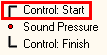
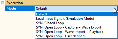
Please refer to the QC user manual for an overview of the execution modes.
Two different main types of execution modes are available using the SYN module:
SYN Closed Loop#
This execution mode uses the internal signal generator and data acquisition simultaneously, but allows defining arbitrary Synchronization Requests where playback and capture are (re-)synchronized by maintaining a flexible sequence execution (e.g. variable numbers of repetitions due to Production Noise Immunity).
If the test setup requires online delay detection and compensation and the device under test provides input for audio playback and capture (with a Klippel Analyzer or a 3rd party audio device), this execution mode should be used. It is more flexible and faster than the open loop modes.
Note
Until QC6 this execution mode was labelled SYN Dynamic Mode.
SYN Open Loop#
The Open Loop execution modes (Capture, Playback, Export and Import) use either the internal signal generator or the internal data acquisition. Arbitrary definable synchronization requests (“trigger points”) allow a flexible triggering of the analysis at the correct point of time.
This mode is used if the playback of stimulus data or capture of response data has to be performed by autonomous devices.
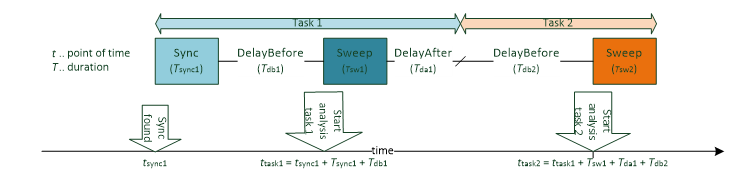
The Open Loop execution modes rely on a static (constant time interval in between the measurements) sequence. After a valid synchronization, the subsequent analysis (or multiple analyses) is triggered based on the fixed distances and durations:
Note
The distance between two measurements must be sufficiently large; otherwise, the capture process might miss its desired start position. The necessary distance depends on the computer system’s performance and the Synchronization Requests. The sync request templates provide enough time in between measurements for virtually all modern computers.
Until QC6 the Open Loop modes were labelled SYN Static Modes.
Capture + Wave Export#
The Open Loop Capture Mode uses the internal data acquisition (of the selected capture audio device) but no playback. The playback of the exported stimulus sequence is realized by an autonomous playback device.
In capture more, the system awaits the synchronization points (triggers) and starts the subsequent analysis (or multiple analyses) once a valid trigger (sync) was found in the input stream (e.g. microphone signal).
The stimulus sequence can be exported to a wave file using the export button.
It is available if a relative or absolute path is entered in the parameter – Wave File:

The specified wave file will be overwritten.
Note
Since the Open Loop execution modes rely on static distances and durations, it is necessary to re-export a sequence if the sequence has changed (e.g., stimulus parameters, delay before/after, sync requests, task order, …).
Note
The capture/export mode activates the stimulus level (dBFS) definition in the measurement tasks (instead of absolute voltage) regardless of the choice of playback device (which is not used).
Application examples:
integrated speakers in media players, TVs, …
in-situ measurement in vehicles with autonomous playback
Wave Import + Playback#
The Open Loop import mode does not use a capture device for data acquisition, but imports the data from a wave file.
The playback mode is one way to play back the static stimulus sequence using the selected audio playback device. It could also be done by an autonomous playback device using the exported wave file.
The parameter – Wave Input Gain provides a possibility to apply an input gain to the complete sequence for correction of input calibration factors:
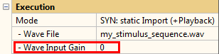
The parameter – Wave File defines the wave file to import.
Application examples:
file writer microphones (Dictaphone)
Mobile recording and offline analysis
User defined#
This option provides direct access to the four Open Loop execution modes (Capture, Wave Export, Wave Import and Playback) without the pairing (Capture + Wave Export, Wave Import + Playback). This should be used if the operation should be integrated into an automated environment and the execution modes need to be defined explicitly.
Synchronization Requests#
General#
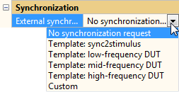
If the sequence operates in one of the SYN Execution Modes, compatible measurement tasks show a synchronization category to define synchronization requests within the sequence:
Note
The template sync2stimulus is not available in some tasks (e.g., leak detection) that do not provide persistent (broad band) excitation.
If a synchronization is requested by a task, the sync search is executed before the corresponding measurement/analysis is performed. Usually, the first measurement task requests a synchronization for itself and subsequent measurements.
Example:

In the example, task 2 uses the synchronized state which was requested by task 1. Task 3 however does request a synchronization directly on the measurement stimulus – no additional synchronization signal is used. Reasons for a re-synchronization in a task sequence are:
The sequence has to be paused after task 2 for an unknown amount of time (e.g., communication with peripherals). The moment of time for task 3 would be unknown, so the sequence needs to be re-synchronized.
Sample frequency deviation between playback and capture device cause delays increasing with elapsing time since the last synchronization. A re-synchronization resets the delay due to sample drift.
The time distances between synchronization signals and sweeps depend on the used execution mode:
In SYN Closed Loop they are as small as possible: after one process (measurement or synchronization) is finished the next is started at the next possible position. DelayBefore and DelayAfter can be used to ensure a minimal distance.
In the SYN Open Loop, the distances have to be large enough to ensure enough time buffer for processing. The Sync Request Templates define DelayBefore and DelayAfter to ensure a reasonable distance in between the processes. If a custom setup is used, the distances should be controlled manually via DelayBefore and DelayAfter.
Types of Sync Requests#
Different synchronization signals are available for every sync request:
White noise
An additional noise signal with constant spectral energy in an absolute band (e.g., the bands 100 Hz .. 200 Hz and 4000 Hz .. 4100 Hz)
This spectral characteristic should be used for a sync request, if the measurement channel provides a pass-band with high frequencies (e.g., tweeter). The additional noise signal is beneficial if the measurement signal is relatively long (e.g., above 1 s).
Pink noise
An additional noise signal with constant energy in a relative bands (e.g., the octaves 100 Hz .. 200 Hz and 4000 Hz .. 8000 Hz)
This spectral characteristic should be used for a sync request, if the measurement channel does not provide a pass-band with high frequencies (e.g., subwoofer). The additional noise signal is beneficial if the measurement signal is relatively long (e.g., above 1 s).
Stimulus of measurement (sync2stim)
No additional synchronization signal is used, the synchronization is performed using the measurement stimulus directly (e.g., the sweep). For short and broadband stimuli, this the most time effective sync request. If the stimulus is long, additional noise synchronization signals should be used.
Note
This sync request is not available, if the stimulus does not provide broad band excitation.
Sync Request Templates#
The following table gives an overview of the available settings for the synchronization request.
- No synchronization request
This setting is used to deactivate a synchronization request. The measurement is performed under the assumption that capture and playback processes are already synchronized.
- Template: sync2stimulus
The synchronization request is activated, but no additional synchronization signal is used. Due to sample rate tolerance (activated by default), the end of the original stimulus is repeated.
- Template: low-frequency DUT
This template requests synchronization for DUTs with very low upper cut-off frequencies (e.g., sub-woofers); a separate 2 s pink noise synchronization signal is used for the synchronization.
- Template: mid-frequency DUT
The template is similar to the previous one but with an additional 0.5 s pink noise synchronization signal. It can be used if the synchronization conditions are quite good.
- Template: high-frequency DUT
This template can be used if the DUT plays back high frequency components (e.g., woofer, tweeter) and the synchronization conditions are very good.
- Custom
No template is used to parameterize the synchronization; all parameters may be set individually. Please refer to Custom Sync Request Parameters.
SYN - Reference#
Setup#
SYN Execution Mode#
- SYN: Closed Loop
In this mode playback and capture of the selected audio interfaces are used simultaneously. Sync requests may be defined by each measurement task for detection and compensation of delays.
- SYN: Open Loop
The Open Loop modes use either the data acquisition or the signal output. The triggering of task stimuli or analyses bases on the fixed distances and durations in the sequence.
Capture:
Data acquisition uses the selected capture device.
No signal output is used.
(The playback device is not used.)
Export:
Signal output uses wave export to output the stimulus sequence.
No data acquisition is used.
(The capture and playback devices are not used.)
Import:
Data acquisition imports response data from wave.
No signal output is used.
(The capture and playback devices are not used.)
Playback:
Signal output uses playback device to output the stimulus sequence.
No data acquisition is used.
(The capture device is not used.)
Sync Request#
Sync Request Templates#
The following table gives an overview of the available settings for the synchronization request.
No synchronization request#
Sync Signal |
None |
Limit |
- |
SRT |
- |
AnaSyncRatio |
- |
MaxTol |
- |
InRouting |
- |
Level |
- |
Time |
- |
Timeout |
- |
ID |
- |
OutRouting |
- |
DelayBefore |
500 ms |
DelayAfter |
500 ms |
HighPassFreq |
- |
MaxSyncTries |
- |
SRT-Ratio |
- |
WaitBeforeSync |
- |
Template: sync2stimulus#
Sync Signal |
measurement stimulus |
Limit |
25 dB |
SRT |
yes |
AnaSyncRatio |
2 |
MaxTol |
3 dB |
InRouting |
same as measurement |
Level |
same as measurement |
Time |
same as measurement |
Timeout (closed loop) |
5 s |
Timeout (open loop) |
60 s |
ID |
- |
OutRouting |
same as measurement |
DelayBefore (closed loop) |
- |
DelayBefore (open loop) |
50% of measurement time |
DelayAfter (closed loop) |
- |
DelayAfter (open loop) |
250% of measurement time |
HighPassFreq |
200 Hz |
MaxSyncTries (open loop) |
1 |
MaxSyncTries (closed loop) |
3 |
SRT-Ratio |
50% |
WaitBeforeSync |
0 s |
Template: low-frequency DUT#
Sync Signal |
pink noise |
Limit |
25 dB |
SRT |
yes |
AnaSyncRatio |
2 |
MaxTol |
3 dB |
InRouting |
same as measurement |
Level |
-3 dB |
Time |
2 s |
Timeout (closed loop) |
5 s |
Timeout (open loop) |
60 s |
ID |
task ID (unique for task) |
OutRouting |
same as measurement |
DelayBefore (closed loop) |
- |
DelayBefore (open loop) |
5 s |
DelayAfter (closed loop) |
- |
DelayAfter (open loop) |
2 s |
HighPassFreq |
50 Hz |
MaxSyncTries (open loop) |
1 |
MaxSyncTries (closed loop) |
3 |
SRT-Ratio |
- |
WaitBeforeSync |
0 s |
Template: mid-frequency DUT#
Sync Signal |
pink noise |
Limit |
25 dB |
SRT |
yes |
AnaSyncRatio |
2 |
MaxTol |
3 dB |
InRouting |
same as measurement |
Level |
-3 dB |
Time |
0.5 s |
Timeout (closed loop) |
5 s |
Timeout (open loop) |
60 s |
ID |
task ID (unique for task) |
OutRouting |
same as measurement |
DelayBefore (closed loop) |
- |
DelayBefore (open loop) |
1.5 s |
DelayAfter (closed loop) |
- |
DelayAfter (open loop) |
0.5 s |
HighPassFreq |
200 Hz |
MaxSyncTries (open loop) |
1 |
MaxSyncTries (closed loop) |
3 |
SRT-Ratio |
- |
WaitBeforeSync |
0 s |
Template: high-frequency DUT#
Sync Signal |
white noise |
Limit |
25 dB |
SRT |
yes |
AnaSyncRatio |
2 |
MaxTol |
3 dB |
InRouting |
same as measurement |
Level |
-3 dB |
Time |
0.1 s |
Timeout (closed loop) |
5 s |
Timeout (open loop) |
60 s |
ID |
task ID (unique for task) |
OutRouting |
same as measurement |
DelayBefore (closed loop) |
- |
DelayBefore (open loop) |
0.4 s |
DelayAfter (closed loop) |
- |
DelayAfter (open loop) |
0.4 s |
HighPassFreq |
800 Hz |
MaxSyncTries (open loop) |
1 |
MaxSyncTries (closed loop) |
3 |
SRT-Ratio |
- |
WaitBeforeSync |
0 |
Custom Sync Request Parameters#
- Sync Request
Default: Sync2stim
Defines the synchronization signal. Pink and white noise signals are available as separate synchronization signals. Sync2Stim defines the measurement stimulus for the synchronization.
- ID
Default: Unique arbitrary integer in range 1..1e5
Defines the synchronization signal’s ID (only for pink and white noise signals)
- Sample rate tolerance
Default: True
Sample rate tolerance allows the synchronization despite of deviating sound card clocks. When the synchronization signal becomes longer, the deviation impacts more on the synchronization.
- Crest limit
Default: 25 dB
Crest factor limit for the impulse response defining a valid synchronization. The reachable crest factor depends on the synchronization signal’s length.
- Level
Default: -3 dB
Peak level (in dB) relative to stimulus peak level
- Time
Default: 0.5s
Time of synchronization signal
- Max. Sync Tries
Default: 3
Number of synchronization tries
- High pass
Default: 200 Hz
High-pass of synchronization process – to suppress room modes
- Input routing
Default: Same as measurement
Defines the input routing used for the synchronization process.
- Input routing channel
Default: Same as measurement (empty)
Defines the input routing channel used for the synchronization – only used for channel-based input (Wave input or 3rd party audio interface)
- Output routing
Default: Same as measurement
Defines the output routing channel used for the synchronization.
Please note that since QC7 (dBLab v212.x) this is always a channel-based vector – also for KA3/PA.
Examples:
KA3/PA Out1:
[1]KA3/PA Out2:
[2]KA3/PA Out1+2:
[1,2]Soundcard or wave output ch1:
[1]Soundcard or wave output ch1+5:
[1,5]Soundcard or wave output ch1..8:
[1,2,3,4,5,6,7,8]Note
For PA/KA3 this channel does not refer to the speaker channel, but to the output channel! The used speaker channel is defined by the amp routing (which maps the output channel to the speaker channel).
Expert Parameters#
If the custom parameters are activated, the user may also activate the expert’s parameters to tweak the synchronization process. Default values are applied in templates and in custom mode with deactivated expert parameters.
- ExtSync.MaxTol
Default: 3 dB
Defines the maximum tolerance to cope with difficult room or speaker configurations that cause multiple possible synchronization points.
The value defines the maximal tolerance to catch the first incident of the synchronization response.
- ExtSync.AnaSyncRatio
Default: 2
Defines the size of analysis window relative to the synchronization signal’s duration.
- ExtSync.Timeout
Default: 5 s for closed loop mode - 60 s for open loop modes
Defines the timeout for the synchronization process.
- ExtSync.SrtRatio
Default: 0.5
Defines the relative amount of repeated measurement stimulus for SRT.
- ExtSync.WaitBeforeSync
Default: 0
Time in seconds, which is ignored for synchronization. Used to force synchronizing on a delayed response.
Parameter Import#
The following table lists the IDs of the SYN module setup parameters and the corresponding text labels (English version) as shown in the user interface of the supported tasks. Only use the IDs for import.
See also
Please refer to section Settings Import in the QC-Manual for more information about importing parameters.
Control Task Parameters#
The execution mode may be defined with parameter import, please refer to Parameter Import in the QC-Manual.
Measurement Task Parameters#
- External Synchronization
- ID:
extSyncSetupType: string constantValues:'ESR_NoReq'(No synchronization request)'Template_Sync2Stim'(template: sync2stimulus)'Template_LowFreq'(template: low-frequency DUT)'Template_MidFreq'(template: mid-frequency DUT)'Template_HighFreq'(template: high-frequency DUT)
- Sync Request
- ID:
extSyncRequestUIType: string constantValues:'ESR_Stimulus'(sync2stimulus)'ESR_PinkNoise'(Pink noise sync signal)'ESR_WhiteNoise'(White noise sync signal)
- ID
- ID:
extSyncIdUIType: numerical value - Sample Rate Tolerance (SRT)
- ID:
extSyncSrtUIType: bool - Crest Limit
- ID:
extSyncLimitUIType: numerical value - Level
- ID:
extSyncLevelUIType: numerical value - Time
- ID:
extSyncTimeUIType: numerical value - Max. Sync Tries
- ID:
extSyncMaxSyncTriesUIType: numerical value - High pass
- ID:
extSyncHpFreqUIType: numerical value - Input Routing
- ID:
extSyncInRoutUIType: string constantValues:'meas'(same as measuremnt)'mic1'(Mic 1)'line1'(Line 1)'mic2'(Mic 2)'line2'(Line 2)
Type: string - Input routing channel (for channel-based output)
- ID:
extSyncInRoutChType: numerical value - Output Routing
- ID:
extSyncOutRoutChType: numeric matrixValues/Examples:[](Same as measurement)[1](Output channel 1)[2](Output channel 2)[3,9,37](Output channels 3,9,37)
Type: numeric matrix - Expert Parameters
- ID:
extSyncExpertType: string matrix
Results#
If a sync request is set, selected results are shown in the summary window.
- SYN Delay
Detected delay between playback and capture process. This delay is compensated in the measurement (the sweep delay should be zero or close to zero).
Only shown in SYN Closed Loop.
- SYN Crest factor
Crest factor of valid synchronization. Shows also the crest threshold defined by the user or the template.
- SYN Sample rate factor
Shows the sample rate deviation between playback and capture process. The reference is the current sample frequency of the used capture device. Only shown if sample rate tolerance is active.
- SYN Delay Before
This setup parameter is shown as an information only in SYN Open Loop.
If a separate synchronization signal is requested, this is the time between the synchronization signal and the measurement signal. If no separate synchronization signal is requested (no synchronization request or sync2stimulus), this is the time before the measurement signal.
The delay may be increased by using the DelayBefore parameter in the routing category of the task. Please note that the maximum of specified delay and delay required by the Sync Request Templates is used.
- SYN Delay After
This setup parameter is shown as an information only in SYN Open Loop.
This is the time delay after the measurement signal.
The delay may be increased by using the DelayAfter parameter in the routing category of the task. Please note that the maximum of specified delay and delay required by the Sync Request Templates is used.
Sample Rate Deviation#
For applications that require the SYN module (e.g., open loop tests), usually the playback and capture hardware clocks are not synchronized. This could impair the robustness of the detection of the synchronization signal.
The SYN module can detect the synchronization signal if the sampling rates (of playback and capture) deviates up to 10 % (this corresponds for example to a WAV file that is sampled with 48 kHz but is accidentally played back at 44.1 kHz). Such high deviations usually impair the measurement results, but the problem can be identified if the synchronization signal is detected and the deviation is shown.
A warning is displayed if the deviation is bigger than 1%:

The actual ratio between the sample rates is shown in the result table
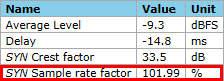
The tolerance against sample rate deviation is activated by default and may be deactivated in custom synchronization requests (please refer to Custom Sync Request Parameters)
Debugging#
If the synchronization is not successful or the synchronization process is not stable one has to debug the setup and find the root cause of the problem.
The processing curves may be requested in category “Display” of each task with an active Sync Request.
Warning
This option produces lots of data and large database files and should be deactivated after debugging the setup.
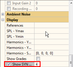
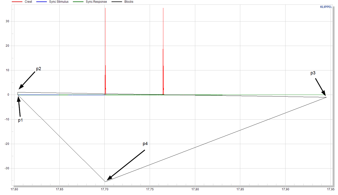
The results are shown in Chart “SYN - Diagnostics”.

The chart is hidden by default, it may be accessed with the button “Show all windows”:

The plotted curves comprise:
The instantaneous crest factor of the envelope of the impulse response. A successful synchronization has to show one or two (if sample rate tolerance is active) distinct peak(s) above the specified crest factor.
Sync stimulus: the stimulus used for the synchronization, showing the moment of playback.
Sync response: shows the time signal of the input channel
Blocks: the analysis blocks – this curve is not affected by the number of seconds specified by parameter “Show SYN processing”. Each block shows the start and end of an analysis block (x coordinates). The xy-coordinates of each block are as follows:
p1: (BlockStart,0)
p2: (BlockStart, 1+SampleRateTolerance)
p3: (BlockEnd, 1-ResampleFactorOfBlock)
p4: (PositionOfHighestCrest, CrestFactorOfBlock in dB)
When debugging the synchronization, please consider the following aspects:
Check the frequency response of the measurement channel: if the upper frequency of the passband is very low, a long synchronization signal is required. A general rule is: a high upper cut-off frequency reflects in short synchronization signals. Is the synchronization successful or more stable with different sync settings? The Template: low-frequency DUT setting should be successful in most scenarios.
Is there a multi-path distribution from audio source(s) to the input? Multiple paths of sound distribution (e.g., multiple active speakers playing the synchronization signal or strong and isolated acoustic reflections) may cause jittering/alternating delays. Check the ExtSync processing curve “Crest” for multiple peaks. If the peaks are very narrow and nearly equally high, the synchronization might alternate due to slightly changed conditions. If the path is optimized, the user may use the expert’s parameter ExtSync.MaxTol to ensure a stable synchronization by forcing the synchronization to use the same (first) impulse of incidence.
If Sync2Stim is used, please ensure a broad-band excitation. The synchronization will not work correctly for very sparse spectra or single tones. Is the high-pass setting of the synchronization compatible to the stimulus frequency range?
Check for other influences: The user may use the option to store the processing curves (Chart “Waveform” while debugging the setup. Due to the amount of data, it’s not recommended to keep the stored processing curves when debugging is finished and production starts.
Check the crest factor of successful synchronizations for one setup statistically to decide on a good and stable limit for a valid synchronization (crest limit). For statistical analysis, the summary log files may be used.
If possible, use unique sync IDs. The initial sync ID is defined when loading a task. Two instances of the same task will have different IDs. Be careful when copying operations or using templates: in these cases, the ID is not changed (since the task is not newly added) and different tests might use tasks with the same ID. The ID is shown in the custom setup of the external synchronization. Sync2Stim setups do not use IDs.
