
MUX – Multiplexer#
Overview#
The Multiplexer hardware is an add-on to the Klippel Analyzer System. It can be used in combination with the R&D system as well with the QC system and in other user specific applications. With 8 channels that can be controlled in different routing modes it provides high flexibility for various applications. The Multiplexer allows selecting one or more input channels from 8 resources or distributing one or two sources to up to 8 receivers. Hardware versions with different connectors and electrical parameters are available for specific use cases.
The Multiplexer can be controlled manually or by the PC within the dB-Lab for RnD and QC applications. The Klippel QC hard / software may control the Multiplexer directly. For the Klippel RnD System the routing is controlled by the USB interface. For other applications the USB interface library may be integrated in the custom software or the command line interface can be used. Alternatively, a parallel port can be used. With a direct access interface to any switch inside the device, fully customized applications may be realized.
Front Side#
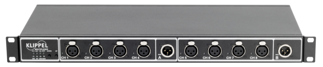
Front side of the Multiplexer (Line-In version with XLR connectors)
The front side of the Multiplexer has the following connectors and controls
- Status LEDs
Status LEDs showing the current status of the Multiplexer. (Routing mode, used control interface and manual operation)
4+4 Routing mode Dual Separate 1 out of 4 selected
2x4 Routing mode Dual Parallel 1 out of 4 selected
1x8 Routing mode Single 1 out of 8 selected
BYP at least 1 relay switch for switched Bypass or switched Shortcut is selected
DIR Direct Control interface is selected
I/O Digital I/O interface is selected
USB USB interface is selected
MAN Manual control is active. Current routing is differing from the last PC controlled state.
- Manual Switch
Manual switch for controlling the Multiplexer in the stand alone operation
- Channel LEDs
The channel LEDs indicating the selected channel.
- IEPE LEDs
The IEPE LEDs at each channel in the MIC version indicating whether IEPE microphone supply is switched on and a microphone is connected.
- Channel connectors
The eight channel connectors can be used as input or output depending on the hardware version.
- BUS connectors
The signals from the eight channels connectors can be routed to the two BUS connectors. The BUS connectors can also be used as input or output connectors.
Attention: High Voltages and / or currents may occur at the Amplifier / SPEAKON connectors. Risk of electrical shock! Use isolated wires, connectors and clamps only. Do not touch metal conductors.
Back Side#
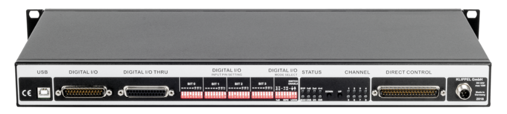
Back Side of the Multiplexer
The back side of the Multiplexer comprises the following elements:
- USB
USB connector for USB controlled operation
- Digital I/O
Digital I/O connector for Digital I/O controlled operation. Connection to Klippel Production Analyzer or PC Parallel Port.
- Digital I/O Thru
The Digital I/O Thru connector allows to daisy chain different Multiplexers or other equipment that can be connected to the Klippel Production Analyzer e.g. Temperature and Humidity Sensor.
- Digital I/O Control Switches
With DIP switches the related input pins for the Digital I/O control mode and the routing modes can be selected.
- Status LEDs
Status LEDs showing the current status of the Multiplexer. (Routing mode, used control interface and manual operation)
BYP at least 1 relay switch for switched Bypass or switched Shortcut is selected
1x8 Routing mode Single 1 out of 8 selected
2x4 Routing mode Dual Parallel 1 out of 4 selected
4+4 Routing mode Dual Separate 1 out of 4 selected
MAN Manual control is active. Current routing is differing from the last PC controlled state.
USB USB interface is selected
I/O Digital I/O interface is selected
DIR Direct Control interface is selected
- Manual Switch
Manual switch for controlling the Multiplexer in the stand alone operation
- Channel LEDs
The channel LEDs indicating the selected channel.
- Direct Control
Direct Control connector for Direct controlled operation.
- Power Supply
Connector for external 24VDC power supply.
Attention: Never use the Klippel Multiplexer at power sockets without EARTH connection!
The used power supply for the Klippel Multiplexer, requires a protective earth conductor for proper operation. If the earth contact is removed it could cause high voltages at the enclosures of the devices.
Operation with Klippel QC#
The Klippel Multiplexer can be controlled from the QC System using the IO-Pins of the Production Analyzer. There are two different ways to control these IO-Pins.
All standard QC Tasks are capable of setting the IO-Pins to control the multiplexer before the measurement is performed.
The other option is to add a distinct IO-Task that allows more individual interaction.
Both options are described below.
Standard Tasks#
To enable the IO-Pin control in the measurement tasks go to the “Control: Start” task and set the Routing parameter “Output” to “controlled by Task“.
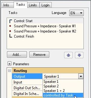
Now the Routing parameter “Digital Out” is available in all standard tasks. The Mux is controlled using 4 bits that correspond to dedicated hardware pins of the Digital IO port (please refer to section Routing Modes). Using the default configuration of the multiplexer, the following correspondence table applies.
Bit |
Pin |
|---|---|
0 |
5 |
1 |
17 |
2 |
4 |
3 |
16 |
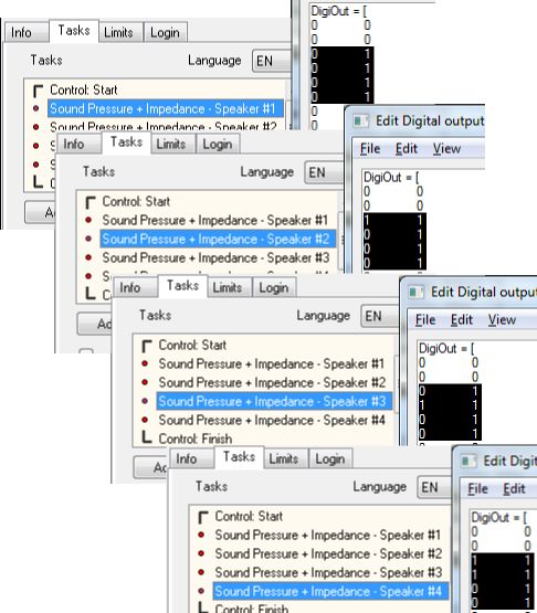
This bit-pin combination corresponds to the lines 3-6 in the DigiOut matrix shown below. To take control over those pins we need to set the mask (second column, marked green) to “1”. If the mask is set to “0” the value specified in the first column is ignored and the state of the pin stays unchanged.
In the example shown, channel 1 is selected.
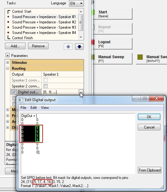
By setting different Pins (Bits) in the different task it is possible to switch through the channels automatically in each test step. In the example sequence shown below the four tasks use different channels (channel 1-4).
Note
Please note that in this example different speakers are switched, but this also applies to input channel multiplexers.
IO Task#
The IO-task is a special task designed not for measurements but to allow interaction with users and automated environments (refer to IO Task Manual). It can be inserted at any point of the measurement sequence.
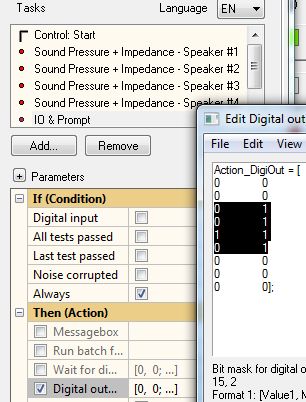
Controlling the output pins is very similar to the standard tasks as described in the previous section, but it may be linked to a certain trigger condition (e.g. “All tests passed”).
You may use this task to set the multiplexer to a defined save state after the measurement is completed. For example, you may switch it to an unused channel to protect operator and DUT from possibly harmful levels.
Connection to Klippel Production Analyzer#
The control connection to the Klippel Production Analyzer is established with the included DB-25 cable. Extensions with standard cables can be done if larger distances between measurement device and Multiplexer have to be bridged. Depending on the quality of the cables, distances of 20m and more should be no problem.
The Klippel Production Analyzer uses the Digital I/O port of the Multiplexer. If additional equipment such as temperature and humidity sensors or other devices have to be connected the Digital I/O port can be daisy chained thru the Digital I/O Thru port.
For the correct settings of the Digital I/O port please check section Digital I/O. If you have ordered the Multiplexer for a specific application, it is delivered preconfigured so that only the software has to be set up to control the device..
Operation with Klippel RnD#
The Klippel Multiplexer can be controlled from the RnD System using the USB interface and the IO Input Output module.
IO Input Output Module#
The Multiplexer control needs no license and can be operated from within the IO module.
The IO operation can be placed before or after any measurement operation into any measurement object to run automated measurement sequences with the batch processing.
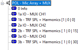
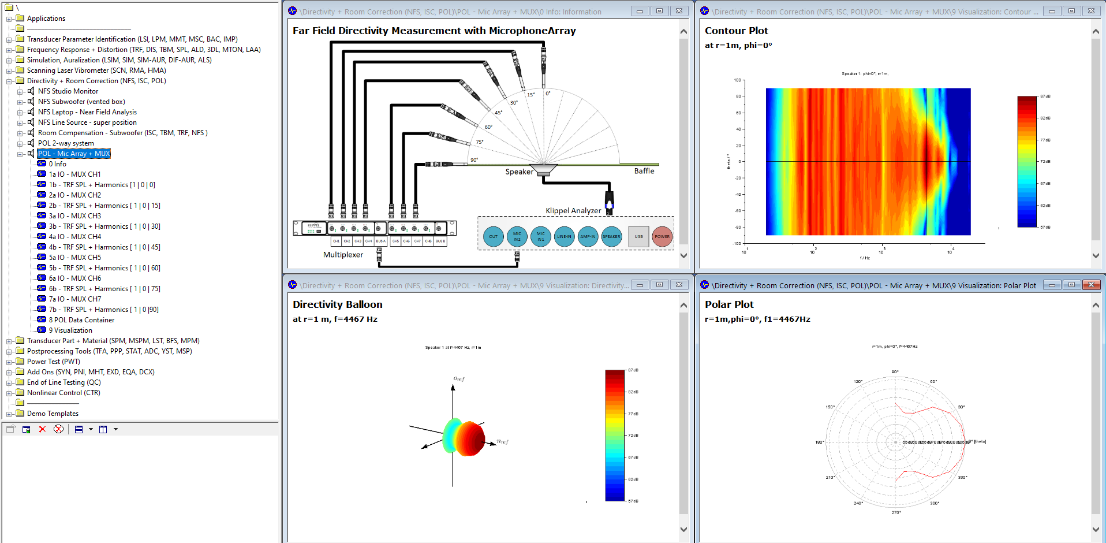
Such a batch can be used to perform Polar Far field Directivity (POL) measurement automatically using a microphone multiplexer.
See Example Database > Directivity + Room Correction (NFS, ISC, POL) > POL - Mic Array + MUX
The Multiplexer hardware can be easily switched into several configuration using the following parameters:
Mode: Routing modes: 1x8, 2x4, 4+4 or Custom
Channel: 1 - 8
Set IEPE CH 1 - 4: selects the IEPE supply for channels 1 to 4 (BNC Multiplexers only)
Set IEPE CH 5 - 8: selects the IEPE supply for channels 5 to 8 (BNC Multiplexers only)
The selection of the multiplexer device is controlled by the same operation. The IO Input Output module can select hardware using the following options:
Automatic
All
By Serial Number
Select List
For detailed information and references see the section IO Input Output of the Tools software manual.
Control Interfaces#
Manual Control#
Independent from the used control port for the automated operation the Multiplexer can be operated in manual mode. At the front and at the back side there is a two way switch or two tactile switches for counting up and down the used channel.
If the Multiplexer is manually controlled and the selected channel is differing from the input state at the used control port, the LED for Manual Control will be active. Manually set to the same configuration as set by the PC will turn off the Manual Control LED, to identify the actual control port configuration. Resetting a manual change by setting the previous configuration again is not possible. Only a changed configuration at the control port will switch of the manual mode.
Example:
MUX is in “1x8” mode and channel “1” is selected after power cycling.
MUX is set to “2x4” mode and channel “2” via USB.
MUX is set to channel “3” by the manual switch. Manual Control LED is on.
MUX is set to channel “2” by the manual switch. Manual Control LED is off, as control port selected configuration is identical.
MUX is set to channel “3” by the manual switch. Manual Control LED is on.
MUX is set to channel “2” via USB. The MUX ignores this command as it is identical with previous control port command. MUX remains at channel 3 and Manual Control LED remains on.
MUX is set to channel “4” via USB. Channel 4 will be selected and Manual Control LED turns off.
The manual switch can be disabled to prevent the accidentally usage of the switch. Also only one direction, count up or down can be disabled.
DIP switch 7 in field Mode Select, disables or enables the count down direction.
DIP switch 8 in field Mode Select, disables or enables the count up direction.
An external switch can be connected to the Digital I/O port for remote Manual mode operation. Hardware option External Manual Switch must be installed to use this feature. For modifying your Multiplexer please contact KLIPPEL support.
Digital I/O#
The Digital I/O port can be used to control the Multiplexer directly from the Klippel Production Analyzer or from PC Parallel Port.
The Digital I/O mode is selected by default, if USB is not selected or the control pin at Direct Control port is not set.
The Digital I/O Thru port passes by all 25 signals from the DB-25 connector for additional devices e.g. Multiplexers or the Temperature and Humidity Sensor for the Klippel QC System.
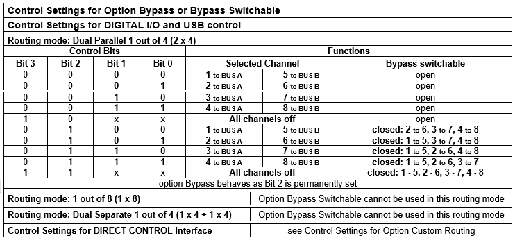
The Multiplexer is controlled in Digital I/O mode by 2 up to 4 bits depending on the used Routing mode. The input pins to control these bits can be free configured according to the following table.
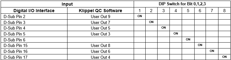
Note
Only one DIP switch per bit must be switched on. Otherwise it will cause malfunction of the Multiplexer. However it is not critical for the device.
Depending on the connected device (Klippel Production Analyzer or PC Parallel Port) the related ground pin has to be selected via a jumper inside the device.
Jumper position right, labeled with pin 1 is needed for connection to the Klippel Production Analyzer.
Jumper position left, marked with pin 18 is needed for connection to PC Parallel Port.
Default Configuration is jumper right for Klippel Production Analyzer usage.
USB Control#
The USB control interface can be used in preconfigured modes to control the Multiplexer in the Routing Modes:
Single 1 out of 8
Dual Parallel 1 out of 4
Dual Separate 1 out of 4.
Similar to the Direct Control interface where each relay switch inside the Multiplexer can be addressed directly to allow any combination of input and output channels, the Multiplexer can be controlled from USB in mode:
Custom Routing
The Klippel RnD System offers an independent multiplexer control operation that can be added to the measurement objects. This Mux control operation allows automatic batch measurements with automatic routing control before or after each measurement.
dB-Lab Operation#
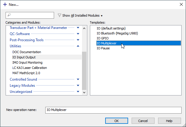
The IO Module with its dedicated Multiplexer Control operation template is included in dB-Lab release >= 210. It documentation can be found in the Tools manual.
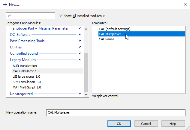
The legacy Multiplexer Control CAL operation is included in dB-Lab release 206 and can be updated to the earlier dB-Lab release 202. For dB-Lab releases < 202 the Multiplexer control is not supported. An online manual how to configure the control operation is included inside the operation.
Command Line Control#
The Multiplexer can also be controlled over the USB interface with a command line and a Scilab interface. Both are documented separately in its library installation package.
The USB driver for the Multiplexer is included in the dB-Lab installation or can be downloaded from: www.klippel.de
Direct Control#
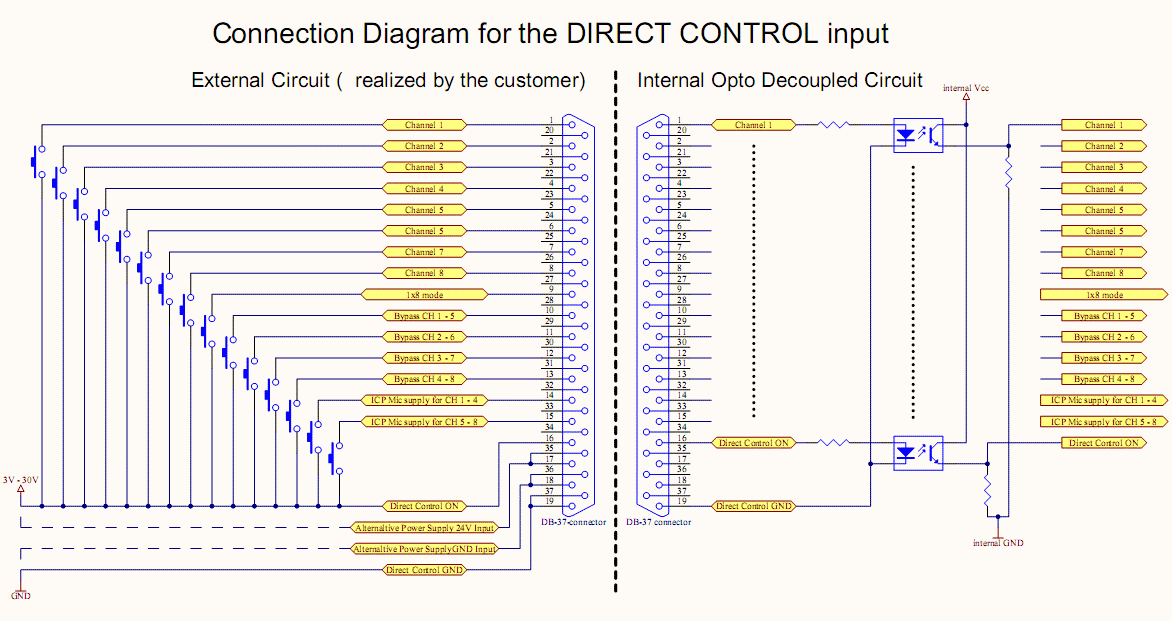
The Direct Control interface allows controlling each relay switch inside the Multiplexer directly. Any combination of input and output channels can be selected.
The interface is optically decoupled for a stable operation in rough environments. All input pins are high active and related to the Direct Control Ground pins 19 and 37.
The high active control signals must be between 3 and 30 VDC and must provide a minimum current of 1 mA.
With a high signal at pin 16 (Direct Control On) the Direct Control mode will be selected.
If the Direct Control interface is realized with 24VDC the Multiplexer can directly be powered via the Direct Control connector. The user has to take care that no external power supply is connected while this option is used.
Routing Modes#
Single 1 out of 8 (1x8)
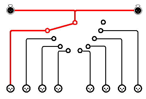
The Single 1 out of 8 routing mode can be selected in the following ways:
for the Digital I/O control interface:
DIP switch 1 & 2 in field Mode Select, must be switched off
Select the channel select bit mask according these table
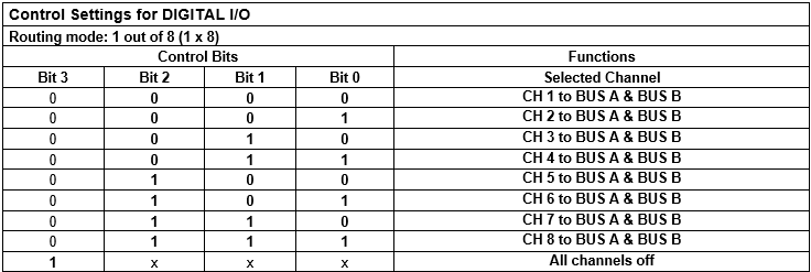
for the USB control interface:
Select the “1x8” mode
Select the channel according the documentation inside the control script or the USB control library
The DIP switches at the backside of the device have no function, with exception of the switch locks
for the Direct control interface:
Pin 9 of the DB37 connector must be at high level
Select the channel Pin according the table at the Custom routing mode chapter
The DIP switches at the backside of the device have no function, with exception of the switch locks
Dual Parallel 1 out of 4 (2x4)#
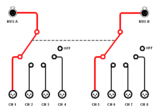
The Dual Parallel 1 out of 4 routing mode can be selected in the following ways:
for Digital I/O control interface:
DIP switch 1 in field Mode Select, must be switched on,
DIP switch 2 in field Mode Select, must be switched off
Select the channel select bit mask according this table
for the USB control interface:
Select the “2x4” mode
Select the channels according the documentation inside the control script or the USB control library
The DIP switches at the backside of the device have no function, with exception of the switch locks
for the Direct control interface:
Pin 9 of the DB37 connector must be at low level
Select the channel Pins according the table at the Custom routing mode chapter
The DIP switches at the backside of the device have no function, with exception of the switch locks
Dual Separate 1 out of 4 (4+4)#
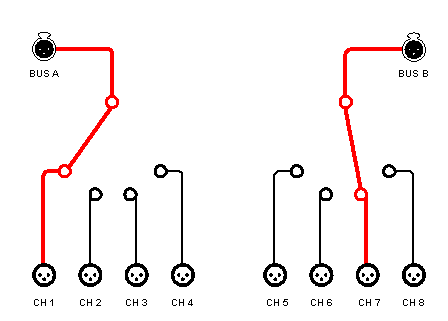
The Dual Separate 1 out of 4 routing mode can be selected in the following ways:
for Digital I/O control interface:
DIP switch 2 in field Mode Select, must be switched on,
DIP switch 1 in field Mode Select, will select the behavior of the manual switch:
DIP switch 1 = off, the count up direction of the switch will count up the channel of bank 1 (channel 1 to 4) independently from bank 2.
The countdown direction of the switch will count up the channel of bank 2 (channel 5 to 8) independently from bank 1.
DIP switch 1 = on, the count up direction of the switch will count up the preselected channels of both banks. The countdown direction of the switch will count down the preselected channels of both banks (channel 1 to 4 and 5 to 8).
Select the channel select bit mask according this table
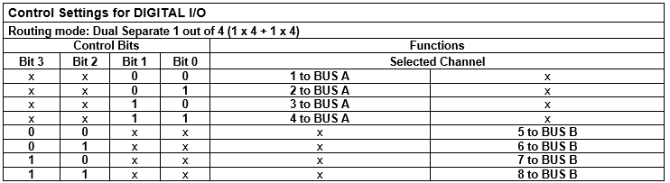
for the USB control interface:
Select the “4+4” mode
Select the channels according the documentation inside the control script or the USB control library
The DIP switches at the backside of the device have no function, with exception of the switch locks
for the Direct control interface:
Pin 9 of the DB37 connector must be at low level
Select the channel Pins according the table at the Custom routing mode chapter
The DIP switches at the backside of the device have no function, with exception of the switch locks
Custom#
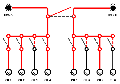
The Custom routing mode can only be controlled by USB or the Direct Control interface. It allows any combination of in- and outputs.
for the USB control interface:
Select the “custom” mode
Select the channels according the documentation inside the control script or the USB control library
The DIP switches at the backside of the device have no function, with exception of the switch locks
for the Direct control interface:
Select the routing according this table.
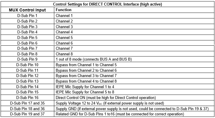
Options#
IEPE Mic supply#
For the BNC hardware version IEPE microphone supply can be switched on separately for each bank (channel 1 to 4 and for channel 5 to 8).
The IEPE LED at each channel will be on only if a microphone is connected.
If IEPE Supply is on for one or both input channel banks, it will be always on at the related channels independently from the actually selected channels. While the IEPE is always on and the connected mic in steady state measurements can be started immediately after a new routing was accomplished.
The Multiplexer BUS output should be connected to a measurement device in the following ways:
KA3: Use BNC input with deactivated IEPE supply or
Use XLR input with deactivated Phantom Power supply. BNC-XLR adapter is included.
DA1/2: Use XLR input with deactivated Phantom Power supply. BNC-XLR adapter is included.
PA: Use XLR Line input.
If the XLR Line input is occupied the Multiplexer BUS output has to be connected to a BNC Mic input where the IEPE supply could not be switched off, an idle load has to be connected for stable operation and distortion rejection.
Therefore an internal load of 3.3 kOhm between the BNC signal and BNC ground can be selected inside the device. In default configuration the internal idle load is deselected by the jumpers J1111 & J1112.
For IEPE mic supply usage the option Switched GND could not be used. See option Switched GND (BNC version) below.
The IEPE microphone supply can be selected
for the Digital I/O control interface:
DIP switch 4 for channel 1 to 4 in field Mode Select, must be switched on
DIP switch 5 for channel 5 to 8 in field Mode Select, must be switched on
for the USB control interface:
Select IEPE_1to4 and / or IEPE_5to8
The DIP switches at the backside of the device have no function, with exception of the switch locks
for the Direct control interface:
Pin 14 and / or 15 of the DB37 connector must be at high level
The DIP switches at the backside of the device have no function, with exception of the switch locks
Bypass#
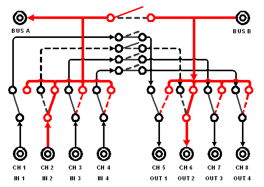
Option Bypass allows switching one measurement device into the signal path of up to 4 channels while the other channels are still connected
Signal from channel 1 is bypassed to channel 5 if channel 1 is not selected (channel 2 to channel 6, 3 to 7, 4 to 8)
If option Bypass is used, only Routing mode Dual 2 out of 4 can be used.
If you want to upgrade your Multiplexer with this option contact KLIPPEL support.
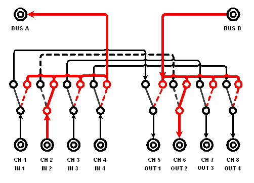
Bypass Switchable#
Option Bypass Switchable offers the possibility to select between Bypass mode or normal operation in all Routing modes.
If Digital I/O or USB coded control interface is used, Bit 2 will close the bypass switches for all deselected channels. This option can only be used in Dual 2 out of 4 routing mode.
If Direct Control or USB direct control interface is used, each of the bypass switches can be controlled separately.
If you want to upgrade your Multiplexer with this option contact KLIPPEL support.
Shortcut#
Deselected channel will be shorted.
It is normally used at Multiplexers in Speaker Version where pin pairs 1+ & 1- and 2+ & 2- are shorted.
Any shortcut combination of all pins in all hardware versions is possible.
Ask KLIPPEL support for a Multiplexer for your special application.
Shortcut Switchable#
Deselected channel 1 – 4 can be shorted. Deselected channel 5 – 8 can be permanently shorted as in option Shortcut.
If Digital I/O or USB coded control interface is used, Bit 2 will close the shortcut switch for channel 1 – 4. This option can only be used in Dual 2 out of 4 routing mode.
If Direct Control or USB direct control interface is used, each of the shortcut switches for channel 1 – 4 can be controlled separately.
Shortcut switchable should be used if the Multiplexer should be used in different routings where also normal operation must be realized.
Option Shortcut as well option Shortcut switchable can for example be used for shorting the passive channel of a coaxial speaker while the other one is measured.
Permanent GND (XLR version)#
Option Permanent GND can be used if all connected devices should be permanently on the same signal ground level.
Normally all pins of the XLR connector are switched. With option Permanent GND pin 1 of all XLR connectors will be connected permanently.
Any permanent connected pins also for the other hardware version are possible. Ask KLIPPEL support for a Multiplexer for your special application.
Switched GND (BNC version)#
The BNC ground signals have to be connected permanently if IEPE supply will be used.
For other applications the BNC ground signals could be switched together with the BNC signal. Therefore the position of the internal jumpers J1101 to J1110 has to be changed. Default configuration is permanent ground for IEPE supply usage.
External Manual Switch#
An external Manual switch can be used for remote manual operation.
The external switch must be connected thru the Digital I/O port. One input pin for each switching direction has to be permanently routed as switch input. This input pins cannot be selected by the DIP switches as input for one of the internal control Bits.
For switching an active high signal between 3 and 30 VDC must be connected to these pins.
If you want to upgrade your Multiplexer with this option contact Klippel, KLIPPEL support
Calibration and Service of the Klippel Multiplexer#
Calibration#
The Multiplexer hardware has no active parts in the signal path that have to be calibrated.
Service#
Klippel recommends checking the Multiplexer periodically depending on the switch cycles, the switched load and the hours of usage per day.
The Klippel Multiplexer uses mechanical relay switches for a minimum influence on the signal properties. This mechanical relay switches have a finite life time and have to be checked periodically. The service cycles are depending on the terms of usage:
Switched load
Switch cycles
Operating hours a day
See Multiplexer specification for life time calculations.
The check can be done by the customer with a simple ohmmeter.
Select every channel one after another and measure the resistance between the Channel connector pin and related Bus pin.
Repeat this step for every pin in every channel.
If the BNC Multiplexer is configured with IEPE microphone supply it has to be checked with an AC signal source due to internal DC decoupling capacitors.
If a service is needed, the service must be done at Klippel.
Malfunction and Troubleshooting#
Overview#
This chapter will provide information that can help you to solve known problems that may occur with the Multiplexer.
If you cannot find a description here that matches your problem, try these options:
Check the Malfunction and Troubleshooting section in dB-Lab. (If Multiplexer is used in connection with the Klippel Production Analyzer.
Check the release notes (CD:Readme.txt and CD:install.txt) that you received with your Klippel Analyzer product. This document contains information about new features, fixed bugs, last minute information and installation problems.
If you cannot find any information about your specific problem, please contact KLIPPEL support
Problems and Solutions#
No connection#
If one or more channels give no connection but the channel LED indicates that this channel is connected please check the connection. Cables, plugs or the connectors can have loose connection. If no reason for a loose connection could be found the contact resistance of the relay switches has to be checked. Switching under overload conditions could cause failures before the mechanical life time of the relay switch is reached. See chapter service for checking the contact resistance.
Connection to Klippel Production Analyzer#
If the Multiplexer fails to respond to the Klippel Production Analyzer, check if LED “I/O” for Digital I/O control mode is on:
Otherwise:
Remove USB and Direct Control cable and switch off and on the Multiplexer.
If LED “I/O” is on check the control pin settings at the DIP switches at the back side of the Multiplexer.
If the control pin setting is correct and signal properties were checked, check the related GND pin jumper inside the device.
Klippel offers a small device called I/O Tester for checking the signals at the Digital I/O interface.
Connection to PC Parallel Port#
If the Multiplexer fails to respond to the PC parallel port, check if LED “I/O” for Digital I/O control mode is on:
Otherwise:
Remove USB and Direct Control cable and switch off and on the Multiplexer.
If LED “I/O” is on check the control pin settings at the DIP switches at the back side of the Multiplexer.
If the control pin setting is correct and signal properties were checked, check the related GND pin jumper inside the device. Default configuration of this GND pin jumper is for Klippel Production Analyzer interface.
Connection to Direct Control interface#
If the Multiplexer fails to respond to your own direct control interface, check if LED “DIR” for Direct Control mode is on.
Otherwise:
Check signal properties at pin 16 at your interface.
If LED “Dir” is on, check the signal properties of each control pin.
Connection to USB#
If the Multiplexer fails to respond to the USB interface, refer to chapter USB connection of the dB-Lab Manual.
MUX Control CAL operation#
If the Multiplexer Control CAL operation input tab does not show the Multiplexer control parameters
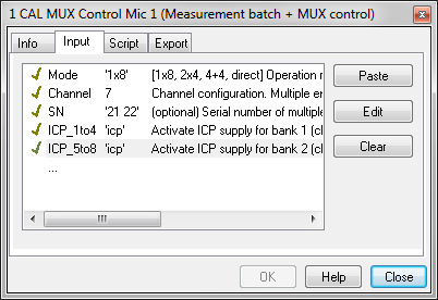
Check if the Multiplexer control script “mux.kdb” is installed on the currently used dB-Lab installation.
If not, download it from the Klippel website: http://www.klippel.de/dm/
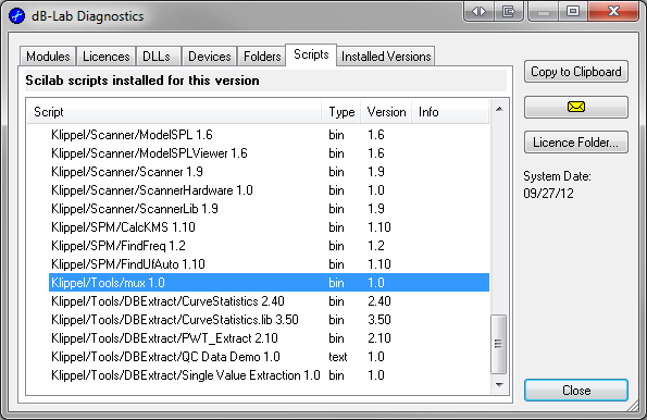
Check if the Multiplexer control script “mux.kdb” is selected in the actual CAL operation.
If not, select it from:
C:ProgramDataKlippelRnD 204.101ScriptsKlippel
The “License Folder…” button in the dB-Lab Diagnostics can be used to navigate to if the folder could not be reached due to user rights limitations.
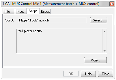
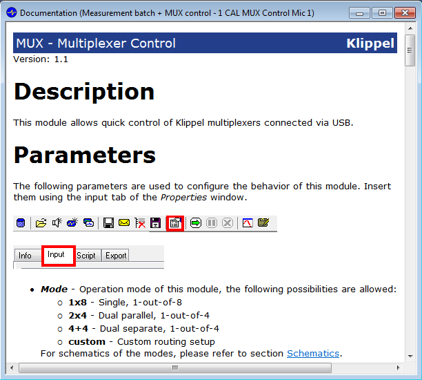
If the script internal documentation could not be shown as shown below but script is loaded correctly as shown above:
Use the Yellow Envelop Button inside the dB-Lab to send your current configuration information together you’re your question to the KLIPPEL support.
Additional Instructions#
Instructions for cleaning#
Do not use any detergent for cleaning the hardware unit. Do not use wet cleaning material. The hardware unit is not protected against wet environments. Please ensure dry conditions and operation within the allowed temperature range.
Revision History#
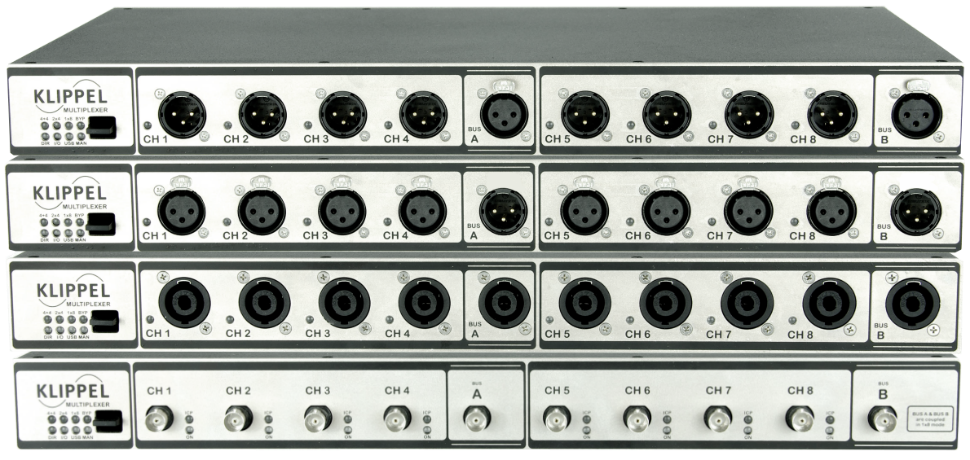
Hardware unit changes outer appearance from serial number 200 onwards. Following changes have been made.
- Enclosure construction has changed and the color scheme has been made identical to the KA3 design.Previous version:
 Actual version: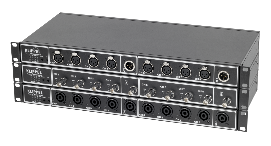
Rocker switch for manual operation has been replaced by two tactile switches to count up/down.
Previous version: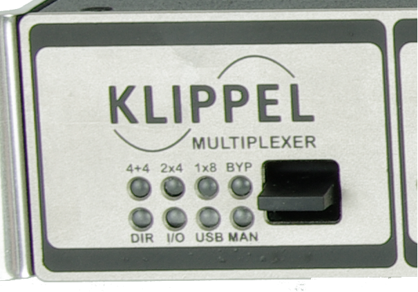 Actual version: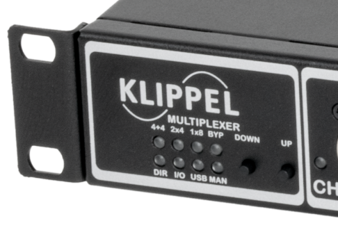
External power supply connector changes from M8 to M12 style connector.
Previous version: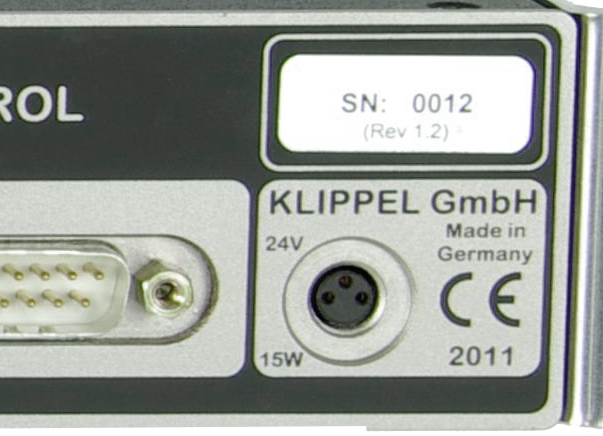 Actual version: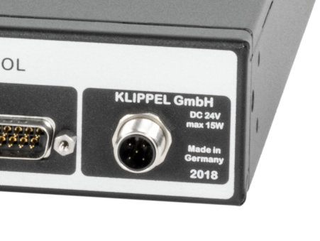
Grounding of the device has been changed. PC-ground, Power-GND, enclosure and Signal Ground are all connected to common protective earth.
Note
BNC ground can still be lifted
