
AUR – Auralization#
Warning
The AUR module is discontinued. The manual also is outdated. You may use older software release versions to have consistent software and manual.
AUR Tutorial#
Overview#
Tutorial 1 reviews the results of an existing Auralization. In the tutorial 2 we perform a first Auralization using the Results of an LSI – Large Signal Identification in the Example Database. Alternatively, you can use the results of one of your own LSI measurements.
The Auralization uses the results of a complete LSI Large Signal Identification to synthesize the audio signal a driver produces with an arbitrary input signal.
The principle and the features of the Auralization module are explained in the reference section.
The 3rd part of the tutorial Customizing AUR gives hints how to use the AUR module efficiently.
Motivation for Auralization#
The Klippel R&D System is mainly used to measure objective parameter and effects of loudspeakers. However, objective measurements can’t answer the following questions:
How strong is the impact on perceived sound quality?
How sounds the individual distortion of different causes?
How can we mask the distortion?
What is the most critical program material?
Are there any desired effects of nonlinear distortion?
Can we increase the performance/cost ratio?
How much benefit brings additional effort?
How will sound the optimized driver?
Systematic listening tests required!
Systematic Listening Tests#
Such listening tests can be performed using the Auralization module.
Features of the Auralization are:
Shows effect of each nonlinearity separately
All state variables monitored over time
Artificial and natural (music) material used as stimulus
Reveals relationship between objective parameters and subjective judgments
Bringing together Engineers and Marketing#
Non-technical listeners (e.g. from a marketing point of view) often have different expectations, questions and ideas than engineers. On the other side engineers have a deep knowledge of all the technical details that can’t be shared with managers. To bring both groups together and to find a common language, the Auralization is perfectly suited. It combines objective parameters and sound quality as well as sensations and constructions.
The audibility thresholds may be used as target values for design and assessment of a particular driver. The physical state variables (maximal displacement, input power, voice coil temperature) monitored during the listening tests show the conditions for the generation of signal distortion and the relationship between effects and physical causes (nonlinearities).
- Development & Manufacturing
Objective Parameters
Distortion from Bl(x), Le(x), Cms(x)
Maximal Output, Displacement
Voice Coil Temperature
Evaluation of Design Choices
Indications for Improvements
- Marketing & Management
Subjective Evaluation
Personal Impression
Sound Quality
Audibility Threshold
Tuning for the target market
Sufficient Headroom
Optimal Performance/Cost Ratio
Viewing AUR Results (part 1)#
The Auralization module is focused on the online listening impression of any excitation signal. That’s why the focus for the module is not on the Tutorial 1 (viewing results) but on Tutorial 2 (Performing an Auralization) and on Tutorial 3 (Customizing the Auralization).
However, it is also possible to analyze the stored data of a preceding Auralization session.
Open the Example Database. Open the folder Diagnostic Examples. From the object 1. Multimedia Woofer, double-click the operation AUR auralization.
Nonlinear Parameter#
The imported nonlinear parameter of the loudspeaker from LSI which shall be auralized are constant, no parameter changes occur over time. Please note that the Auralization incorporates a full thermal model. Increasing of Re due to heating and changes of Qes can be monitored over time in the result window Re(t), Qes(t).
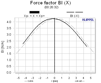
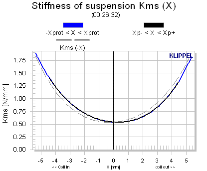
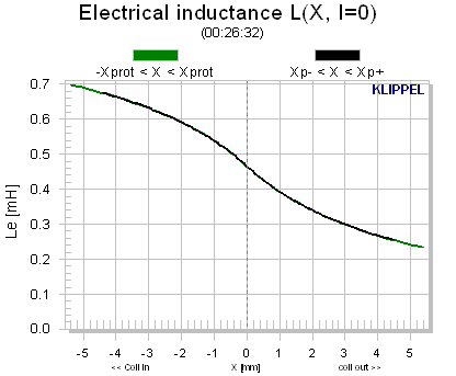
Open the result windows Bl(x), Kms(x) and Le(x).
Viewing states over time#
The states of the speaker (e.g. temperature, power, displacement) are dependent on the input signal and vary over time.
Open the result window Temperature, Power
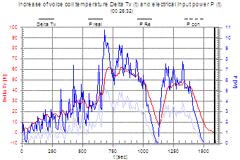
The temporal history of the measurement can be investigated. It can be checked, if the simulation of the driver is appropriate to its design (e.g. the voice coil temperature did not exceed mechanical limits).
Open the result window Displacement
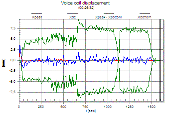
Here the maximal displacements (peak and bottom) as well as dynamically generated offsets in displacement can be verified.
Performing a new AUR (part 2)#
In this tutorial we perform a first Auralization using the LSI results stored in the #Example Database*.
Setting up the hardware#
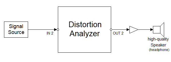
The equipment comprising
Signal source (CD-player, signal generator)
Reproduction system (headphone or high-quality monitoring speaker)
personal computer with USB interface
is connected in the following way:
Audio Signal Source is connected to Input IN 2 of the Distortion Analyzer.
Output OUT 2 of the Distortion Analyzer is connected to the headphones/loudspeaker system.
Connect the PC to the DA via the USB interface.
Running the Auralization#
First, we create a new Auralization operation in dB-Lab, and import the results of an LSI measurement:
Select or create a new Driver in a database of your choice (for details see the Tutorial dB-Lab Pro or Tutorial dB-Lab Lite in the dB-Lab manual)
Choose
 Edit / New
Operation from the menu
Edit / New
Operation from the menuIn the New Operation dialog, select an AUR Auralization operation in the list to the left, and Click OK. The new operation is added to the example driver 1.
Select the LSI Large Signal operation
Click
 View
Properties, and select the Im- / Export property page
View
Properties, and select the Im- / Export property pageClick Export to clipboard
Select the Auralization operation you just inserted
Select the Im- / Export Property Page
Click Import from Clipboard. “Data available” should be indicated on the property page (if not, please refer to the troubleshooting section)
We can now start the Auralization:
Start the CD Player (or your signal source)
Double-click the Auralization operation to open its default windows.
Open the property page AURALIZATION. Close the Output attenuator, and set input to about –6dB.
Start the Auralization by pressing
 Run.
Run.Adjust the volume of the headphone signal with the slider Output, and adjust the high pass signal level with the slider tweeter, so that you hear the distorted signal in the headphones or monitor.
Now you can explore the different settings:
The Input slider controls the driving level of the simulated unit. The simulated working range is also displayed in the nonlinearities result windows (Bl(x), Cms(x), Le(x)) as a black line.
Adjust the Input slider so that the working range covers almost the entire range used in the measurement, but stays slightly below.
The sliders Linear, Bl(x), Cms(x), Le(x) are a mixing console to attenuate the different signal components: the undistorted linear part, and the distortion added by the individual nonlinearities.
Reduce the linear signal by shifting the slider Linear to –100dB. Now you will hear the distortions only. You can sharpen the effect by driving the speaker further into the nonlinear domain. For this increase the input level with slider Input.
Play around with the slider Bl(X), Cms(X), Le(X) and listen to the effect. Switch off all sliders but one and listen to the distortion separated of that particular nonlinearity.
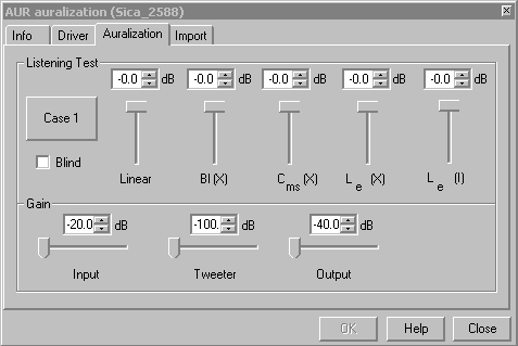
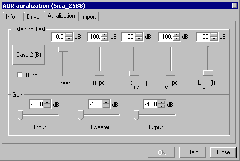
Compare two different settings. Choose the first setting, press button Case 1 (A) and adjust second setting. Toggle between the two settings by pressing Case 1 (A) / Case 2 (B).
- You may pause the Auralization by pressing
 . You finish the Auralization by pressing
 .You can later review the distortions and displacement over time, as well as the instantaneous speaker states.
 Additionally it is possible to add the unprocessed tweeter signal (in case of importing data from LSI Woofer measurements) via the slider Tweeter (linear). In case of importing measurement data from LSI Tweeter measurements this slider will become Woofer (linear) instead for adding the unprocessed woofer signal. The crossover frequency for the Tweeter channel is fixed at 1500 Hz while the crossover frequency can be adjusted manually for the Woofer channel.
Customizing AUR (part 3)#
Measurements Below Threshold#
Using an uncritical stimulus (e.g. not enough bass) in the Auralization of a high-quality driver the distortion might be inaudible for some listeners. To determine the threshold of audibility in this case the amplitude of the linear signal may be attenuated (SLinear= -6 dB) to enhance the nonlinear distortion in the reproduced output. This enhancement may be interpreted as an additional headroom in the detection of the distortion. Trained listeners are much more sensitive to the distortion and will give the loudspeaker less headroom than inexperienced subjects.
Analyzing one Nonlinearity only#
Setting the linear slider and one nonlinearity to 0 dB and the others to –100dB one can listen to the impact of one distortion only. This helps to identify the source of most annoying distortion. Furthermore it is possible to find the threshold of audibility for each nonlinearity for a typical test signal. This may reveal where (on which nonlinearity) money can be saved or has to be spent.
Critical Test Signals#
Since arbitrary test signal may be used with the Auralization, it is important to select the most critical signals for obtaining relevant data. Here a short overview is given, which signal should be used for which application.
- One Tone
Only harmonics
Perceived as low frequency „spectral coloration“
Distortions from Le(x), Cms(x), Bl(x) sound similar
- Two Tone (Base+Voice)
Very critical
Distinct perception of individual distortion
Very low spectral masking
- Music
Close to reality
Results strongly depend on chosen material
Higher masking than two-tone
A/B-Listening Test#
The A/B Listening test makes it easy to compare different settings of the sliders. Here an example to compare a linear (ideal, no distortion) and the real driver is shown. Of cause all other setting may be used. This test is very useful to find audibility thresholds of distortion since the user has access to the sliders.
This mode is optimal for initial training of the listeners and to select a music program used as a critical or representative stimulus in systematic listening test.
Total Output (all distortion)
Linear Output
Double Blind Listening Tests#
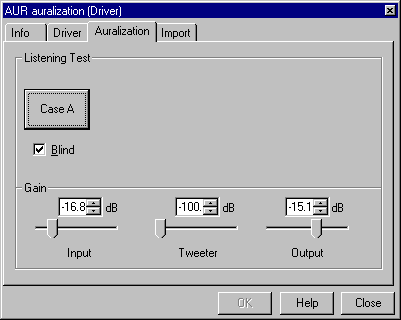
For systematic tests it is crucial to hide the setup information from the test person as well as from the operator. This removes any bias from the tests and the reproducibility may be tested. After setting the controls for both cases, click on the Blind checkbox to activate the blind listening test. The two cases from the A/B-Test are now renamed randomly from case 1 and case 2 to case A and case B.
Case A
Case B
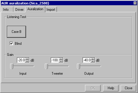
By removing the check from the box the sliders become visible again, and the Case button shows the relation between A/B and 1/2. The response from the test person can now be correlated to the hidden setting.
Online Distortion Monitoring#
By changing the slider settings the momentary distribution of distortion components will be changed. Furthermore the distortion depend on the test signal (music material) and level considerably. In the result window Distortion peak values of distortion are presented over time and allow to correlate subjective impressions and objective distortion measures.
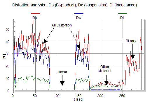
The Distortion window, together with a listening test, gives a direct correlation between objective measurement and subjective impression.
Online State Monitoring#
The loudspeaker states can be monitored by checking the corresponding windows
Voltage, Current,
Displacement and
Temperature, Power.
In this history the operating conditions can be checked.
Note
The Auralization does not generate a warning, if the maximum displacement used to identify the nonlinearities in the LSI is exceeded. It is the responsibility of the user to ensure reasonable conditions.
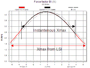
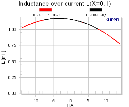
In all result windows of the nonlinear characteristics the instantaneous displacement range (of the last update interval, 2 seconds) is shown as a black curve. The red curve indicates the maximum displacement measured in the LSI while identifying the nonlinear behavior.
Analyzing Synthetic Signals online#
Synthetic signals such as one or two tone signals are simple signals, where the generation of nonlinear effects can understood. It is a very powerful tool to use the Auralization with two sine generators and an FFT analyzer to see the impact of nonlinearities on the distortion online.
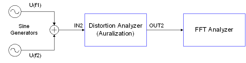
The Nonlinearities can be changed within the AUR signal and the excitation can be changed manually at the generators.
Audibility#
The audibility of distortion is very complex and depends on many factors. The most important factors are described below:
- Spectral properties of the Stimulus
Low frequency components (generate displacement)
High frequency components (cause intermodulations)
Sparse spectrum (low spectral masking)
Stationary characteristics (low temporal masking)
Natural sound (familiar to listener)
Most critical with steady-state signals
- Preshaping He(f) of the input signal
Crossover, Highpass filter to limit displacement
- Driver Parameters (nonlinear System)
Kind of nonlinearity, limiting effects
linear parameters (fs, QT, …)
- Post-shaping of distortion H(f, r)
Propagation in the sound field (linear) in the room
Transfer function of the headphones
- Noise
Masking effects by noise
- Listener
skills, training
Safety Margin#
The safety margin described the factor by which the distortion can be multiplied to become audible relative to the linear signal. The higher this margin is, the lower are the distortion and the better is the driver. This is an objective measure for a specified music material.
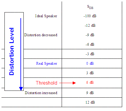
To obtain this value, decrease the linear signal to –12 dB and adjust the input slider to a reasonable working range (displacement, power, temperature).
Now set all distortion sliders to –24 dB and increase them step by step until the distortion are audible for most listeners. The difference of distortion level and linear level is the Safety Margin.
AUR – Reference#
Warning
The AUR module is discontinued.
Overview#
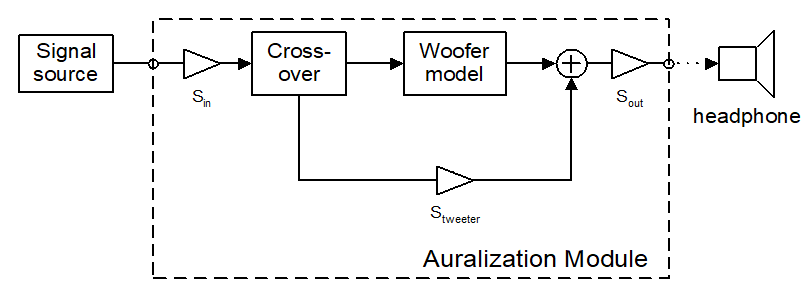
The module “Auralization” simulates the acoustic output of a loudspeaker system in the far field on the basis of the identified large-signal model processed by the Distortion Analyzer 1 in real time. Before processing any external input signal supplied to terminal IN2 the linear, nonlinear and thermal parameters of the woofer driver have to be measured using the LSI Pro module. An additional tweeter channel can be activated via a crossover system to transfer an audio signal with full band-width. The identified model allows to separate the nonlinear distortion db, dC, dL generated by the force factor, the compliance and the inductance. In the simulated sound pressure signal p(t) the linear component plin(t) and each nonlinear component pb(x), pL(x), pC(x) can be attenuated separately to modify the transfer response of the woofer and to investigate the impact on the subjective listening impression. Systematic listening tests can be performed by using the blind A/B switch.
Auralization Technique#
How does it work?#
In order to synthesize the loudspeaker output for any input signal in real time the set of nonlinear differential equations is transformed into the digital domain and implemented in a digital signal processor. Generating an identical copy of the driver in the digital domain makes it possible to check validity of the physical modeling, the nonlinear parameter measurement and the numerical calculations. Above that the digital modeling allows to modify the nonlinear transfer response of the driver virtually in order to investigate the effect of each nonlinearity separately.
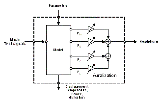
Digital transducer model#
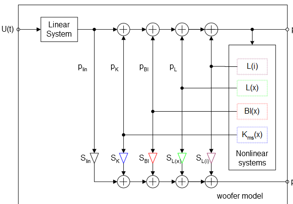
In contrast to the simulation SIM, the Auralization does not modify the nonlinearities of the driver but investigates their effects in the output signal only. Thus the nonlinear differential equation and the parameters of the particular driver are kept unchanged during Auralization. The equation produces internal state variables (displacement, velocity, temperature) of the real driver. The output of the digital model is the radiated sound pressure signal p(t) in the far field of the driver. However, in the nonlinear differential equation the sound pressure p(t) is the sum of an undistorted output plin(t) and the distortion components pC(t), pBL(t), pL(x)(t) and pL(i)(t). The undistorted output is linearly related to the drivers input u(t) and the distortion components pC(t), pBL(t), pL(x)(t) and pL(i)(t), generated by nonlinear subsystems representing the nonlinear stiffness, Bl-product and inductance, respectively. The nonlinear subsystems are provided with the output plin(t) forming a feedback loop, where the generated distortion components react to the state variables and their own generation process. This feedback loop causes the complicated behavior of the nonlinear system at large signals (compression, jumping effects).
Tapping State Variables#
In the Auralization the summing point in the feedback loop is copied by tapping the linear signal #plin(t)# and the nonlinear distortion #pC(t), pBl(t), pL(x)(t) and pL(i)(t).# Scaling them by the attenuators Slin, SK, SBl, SL(x), SL(i) and summing up the components will produce the Auralization output p(t)’. Changing the gain of the attenuators any desired ratio between the distortion components and the linear signal can be realized in order to determine the audibility of the distortion in listening tests. Clearly, setting all gain controllers equal to one will yield the real driver output.
Import of Driver Parameters#
The linear, nonlinear and thermal parameters of the driver under test are imported from the LSI – Large Signal Identification software module via the clipboard.
Input Signal#
The Auralization technique may be applied to any input signal (natural audio signal or a synthetically generated test signal).
Reproduction System#
A high-quality loudspeaker system or headphone is required for the reproduction of the Auralization output. The linear amplitude response should be sufficiently constant in the interested frequency range. The reproduction system should be operated far below the maximal limits to keep the distortion low.
Result Windows#
The results of the measurement give information about state, parameters and setup. Please find detailed information on the results windows in the Reference of the software module Large Signal Identification LSI.
- Bl(x):
electrodynamic coupling factor, also called Bl-product or force factor Bl(x) versus displacement
- Cms(x):
Compliance CMS(x) of the mechanical suspension (inverse of the Stiffness KMS(x) versus displacement x
- Le(x):
electrical inductance Le(x) of voice coil displacement versus displacement x
- Le(i):
electrical inductance Le(i) of voice coil displacement versus input current i
- fs(x):
Instantaneous resonance frequency versus displacement x.
- Qts(x):
Total Q factor versus displacement x.
- Re(t), Qes(t):
Temporal change of DC resistance and electrical Q-factor due to heating versus measurement time t.
- Voltage, Current:
peak and rms values of voltage u(t) and current i(t) at transducer terminals versus measurement time t
- PDF Voltage:
Probability density function of voltage at the terminals
- Temperature, Power:
voice coil temperature Tv and real input power P versus measurement time t
- Distortion:
peak distortion caused by Bl(x), Cms(x) and Le(x) versus measurement time t.
- Displacement:
peak and bottom value, difference and averaged DC value of voice coil displacement x versus measurement time t
- PDF (X):
Probability density function of displacement x
Property Pages#
After activating AUR you can open the property pages. These pages present the setup parameters for measurement and result analysis.
- INFO:
The INFO page allows the user to change the name of the measurement and to add a comment to the measurement.
- DRIVER:
The DRIVER page contains special transducer parameters that have to be provided by the user.
- AURALIZATION:
The STIMULUS page is used to adjust the attenuators for the linear and the distorted signal. Furthermore the input and the output attenuators and the tweeter channel can be modified. In order to compare different setting the used may toggle between two settings.
- IMPORT:
In his page the linear, nonlinear and thermal parameter can be imported form LSI
INFO Page#
The INFO page allows the user to change the name of the measurement and to add a comment to the measurement (comments may be included in the report file).
DRIVER Page#
The DRIVER page contains special transducer parameters that have to be provided by the user.
- Diaphragm Area:
\(S_d\) in \(cm^2\) The diaphragm area is the effective projected surface area of the driver diaphragm
- Diaphragm diameter:
\(d_d\) in \(cm\) Diaphragm diameter of the driver.
- Impedance:
\(Z_n\) in \(\Omega\) Nominal impedance of the driver (customer rated value)
- Power:
\(P_e (max)\) in \(W\) Maximal nominal input power (customer rated value)
- Material of voice coil:
The kind of material (copper, aluminum) used for the voice coil has to be specified if known. This information is used to identify the increase of voice coil temperature from the variations of the voice coil resistance.
AURALIZATION Page#
The following table gives a summary on the elements of the property page:
- Slider Linear
Attenuator for the linear (undistorted) portion of the output signal
- Slider Bl(X)
Attenuator for the portion of the output signal that is distorted due to the force factor (Bl) nonlinearity
- Slider Cms(X)
Attenuator for the portion of the output signal that is distorted due to the compliance (Cms) nonlinearity
- Slider Le(X)
Attenuator for the portion of the output signal that is distorted due to the inductance Le(x) nonlinearity
- Slider Le(i)
Attenuator for the portion of the output signal that is distorted due to the inductance Le(i) nonlinearity
- Blind
Used for blind or double blind tests. Hides the Linear, Bl(X), Cms(X) and Le(X) sliders
- Case 1/ Case 2
Toggles between two different settings of the Linear, Bl(X), Cms(X) and Le(X) sliders
- Slider Input
Attenuator for the speaker input signal. Increasing the speaker input signal will drive the speaker further into the nonlinear range of operation
- Slider Output
Attenuator for the Auralization output signal. Used for adjusting the volume for the reproduction system
- Slider Tweeter
Attenuator for the tweeter channel. This slider will become the woofer channel in case of importing measurement data from LSI Tweeter instead of LSI Woofer.
For the woofer channel the crossover frequency can be adjusted additionally between 20…3000 Hz while it’s fixed to 1500 Hz for the tweeter channel.
Sliders for Signal Components#
The output of the nonlinear transducer model is the superposition of the linear sound pressure output and the nonlinear distortion produced by the driver nonlinearities (force factor Bl(x), compliance Cms(x) and inductance Le(x)). Each signal may be weighted by a gain controller (slider) before summing up to the output signal.
Slider Settings in dB:
Output Signal |
Linear |
\(Bl(X)\) |
\(C_{ms}(X)\) |
\(L_e(X)\) |
\(L_e(I)\) |
|---|---|---|---|---|---|
Slider Setting |
\(S_{Linear}\) |
\(S_{Bl}\) |
\(S_{C}\) |
\(S_{L}\) |
\(S_{L}\) |
Real Transducer |
0 |
0 |
0 |
0 |
0 |
Ideal Linear Transducer |
0 |
100 |
100 |
100 |
100 |
\(Bl\)-distortion only |
100 |
0 |
100 |
100 |
100 |
\(C_{ms}\)-distortion only |
100 |
100 |
0 |
100 |
100 |
\(L_e(x)\)-distortion only |
100 |
100 |
100 |
0 |
100 |
\(L_e(i)\)-distortion only |
100 |
100 |
100 |
100 |
0 |
Increase of distortion by 6dB |
6 |
0 |
0 |
0 |
0 |
Decrease of distortion by 6dB |
0 |
6 |
6 |
6 |
6 |
Sliders for Gain Control#
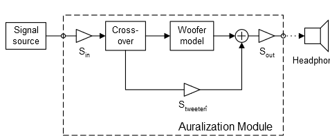
- Slider Input
The input signal is attenuated by the gain controller Sin to produce displacement xpeak that is typical for the application of the driver. If the amplitude of the signal source or the gain controller Sin is set to a low value the woofer is operated in the small signal domain and the woofer behaves almost as a linear system.
- Slider Output
The gain controller Sout applied to the output signal controls the volume of the sound at the headphone. This slider does change the relative distortion measures (dtot, d2, d3 in percent) since the linear signal and all nonlinear distortion components are attenuated in the same way.
- Slider Tweeter
If the driver under test is intended for a woofer or subwoofer channel an additional tweeter path can be realized by using a crossover. The gain controller Stweeter may be used for attenuating the gain of the tweeter channel. The crossover frequency in this case is fixed at 1500Hz.
When importing data from LSI Tweeter to the AUR this slider will become the Woofer channel. In this case the crossover frequency can be adjusted manually.
A/B-Comparison#
The user may switch between two settings of the attenuators to perform a direct AB=comparison between two cases (Case 1 and Case 2). Normally one case represent the virtual linear driver (#SLinear#=1, #SBl#=0, #SK#=0, #SL(x)#=0, #SL(i)#=0 ) and the second case represents the real driver considering all distortions (SLinear=1, SBl=1, SK=1, SL(x)=1, SL(i)=1 ).
Open Test#
In the open test mode the user has access to all attenuators to change the amplitude of the linear and distortion components, the tweeter, the input and output signal. The simple intuitive user interface makes it easy to become familiar with the Auralization technique. This mode is optimal for initial training of the listeners and to select a music program used as a critical or representative stimulus in systematic listening test.
Blind Test#
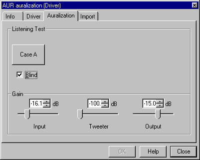
These tests may be performed as blind or even double blind tests to avoid any bias and to check the reproducibility of the results. During the blind test the user has no access to the attenuator for the linear signal and the distortion but may adjust the input, output and tweeter amplitude. The designation Case 1 and Case 2 will be renamed by chance to Case A and Case B in order to hide the setup to the subject. The amplitudes of all state variables and distortion components are monitored during the blind test and stored in the history file. The setup may be viewed after the test to determine thresholds of audibility.
IMPORT Page#
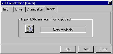
The Auralization requires the parameters of the digital transducer model provided by the Large Signal Identification LSI pro copied via the clipboard into the Auralization module by the following procedure.
Perform a LSI Pro - measurement. Valid parameters of the transducer become available after the Enlargement Mode. This is shown in dB-Lab by replacing the Cancel button
 by the Save/Finish
button
by the Save/Finish
button
Press Save/Finish button and choose Finish to save the results of the LSI.
Open the Im/Export Page in the LSI and copy LSI data to clipboard by pressing the icon
 .
.Open the Im/Export Page in AUR and copy the clipboard parameter into AUR by pressing
 . The message Data
available shows that this operation has been performed successfully.
. The message Data
available shows that this operation has been performed successfully.Now you may start the Auralization measurement by pressing Start
.
Malfunction and Troubleshooting#
Overview#
This chapter will provide information that can help you solve common problems that occur with the Distortion Analyzer and the AUR module. The software generates a variety of warnings and error messages described below.
If you cannot find a description here that matches your problem, try these options:
Check the Malfunction and Troubleshooting section in dB-Lab documentation.
Check the file readme.txt that you received with your Distortion Analyzer products. This document contains the most up-to-date information about products and installation procedures.
Contact us via KLIPPEL support .
Error and Warning Messages#
Parameter Import from LSI#
Please make sure that:
The LSI was run with the LSI Pro module (LSI Standard results are not sufficient for an Auralization)
No exception occurred while the LSI was running
The LSI was not terminated before the end of the nonlinear mode
To import the LSI data into the Auralization, choose Export to Clipboard on the LSI’s Im/Export property page. Make sure the clipboard indicator in the status bar (bottom right corner) reads “LSI Parameters”. Choose Import from Clipboard on the Import property page of the Auralization. Do not edit this data, changing the parameters with the internal editor will not affect the auralization itself.
No Device-Dependent Calibration#
- Error message
“No device dependent calibration data used, only default values!”
- Reason
The Hardware unit is not calibrated. All results acquired are invalid.
- Solution
Choose “Cancel” to cancel the measurement. Switch the hardware unit off, and on again, and start the measurement again.
If the error occurs again, contact Klippel or your local distributor for calibration of the hardware unit.
Data already available#
- Error message
“Data is already available. If you continue, this data will be discarded!”
- Reason
You are changing a setup parameter that has an effect on the measurement results. (e.g., changing the stimulus parameters)
- Solution
Click “Cancel” to keep the results with their original setup. Click “OK” to discard the previous measurement results and accept the setup change.
New measurement active#
- Error message
“A new measurement is active in the Distortion Analyzer. Please start the corresponding operation to reconnect with the device.”
- Reason
The operation running in the hardware unit has been changed by external means (standalone, second instance of dB-Lab, etc.)
- Solution
The operation that displays this message will disconnect from the hardware unit, allowing the new operation to continue.
LSI parameters are incompatible#
- Error message
“LSI parameters are incompatible with current AUR version”
- Reason
AUR Release 200 requires results from LSI 2 (that is, LSI Woofer, LSI Tweeter or LSI Woofer Box).
Respectively, earlier versions of AUR require LSI 1 results (then named only “LSI large signal”).
- Solution
Make sure you use LSI 2 results for current versions of Auralization, or use an older version of dB-Lab to perform Auralization of LSI 1 data.
Note that starting with Release 200, you can install multiple versions of dB-Lab in parallel, also in parallel to one older version.
