
NFS – Near Field Scanner Baffle - Assembly#
Hardware Revision: 1.0
Requirements#
Hardware#
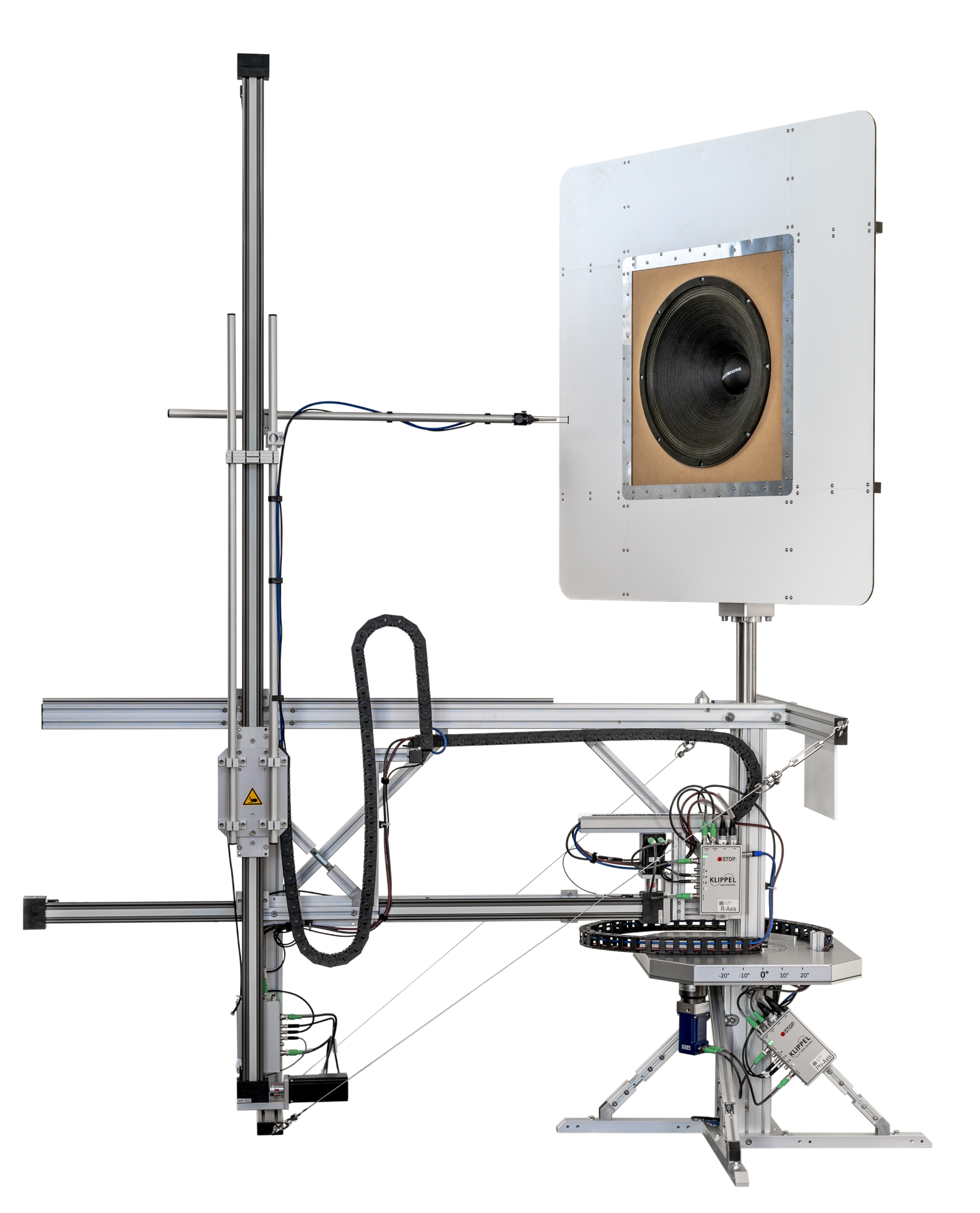
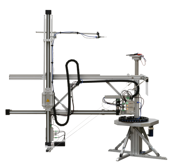
NFS – Near Field Scanner Hardware
Tools#
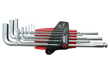
Allen keys - metric (included in Near Field Scanner Hardware) Tool is not included in NFS Baffle Package!
List of Parts#
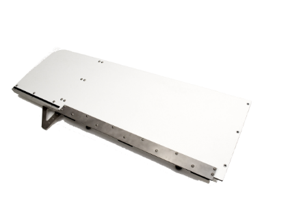
- 2 Alu-Dibond® baffle panel (No. 1-4)
- Quantity: 4
- 2.5 small bracket (19 mm)
- Quantity: 4
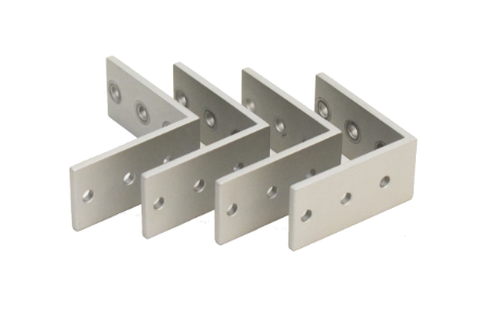
- 1.6 large bracket (24 mm)
- Quantity: 4
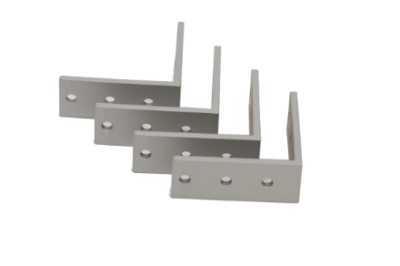
- 1 base plate
- Quantity: 1
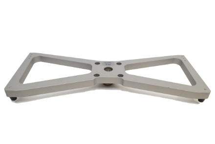
- 3+4 struts (left/right)
- Quantity: 2
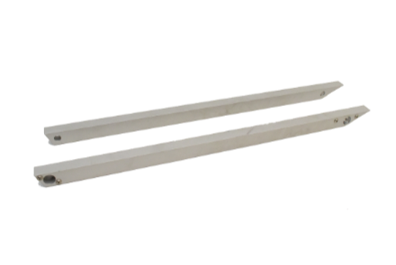
- 1.9 flange adapter
- Quantity: 1
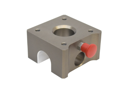
- 43 calibration cone
- Quantity: 1
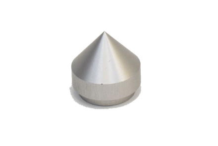
- 7.1 calibration cone holder
- Quantity: 1

- 5 tensioner
- Quantity: 4
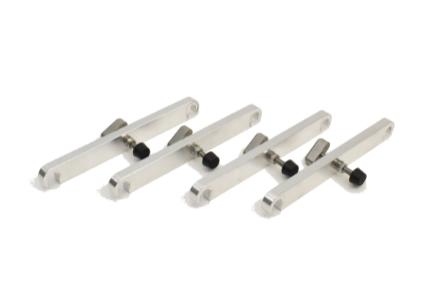
- 1.4 cylinder head screw M10x30 mm
- Quantity: 8
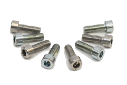
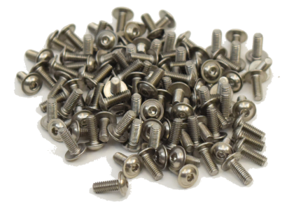
- 2.4 panhead screw M4x10 mm
- Quantity: 112 + (5 spare)
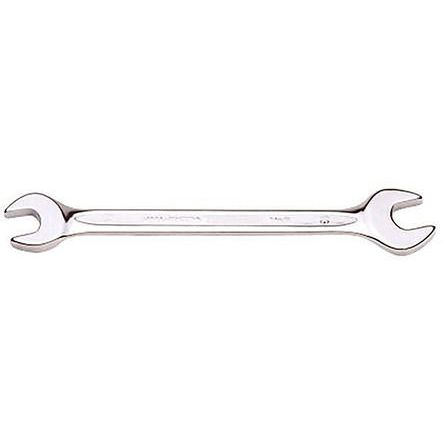
- 8.1 wrench 8/10 mm
- Quantity: 1
Assembly Instructions#
Placement of Panels#
Parts#
- 2 Alu-Dibond® baffle panel
- Quantity: 4
Instructions#
Place the 4 Alu-Dibond® baffle panels in the following order. The number increases clockwise.
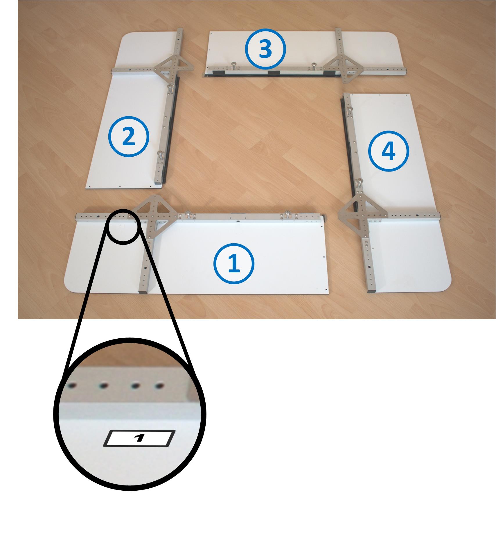
You can find the number of the panel on the attached label.
Unscrew Corner Plates#
Instructions#
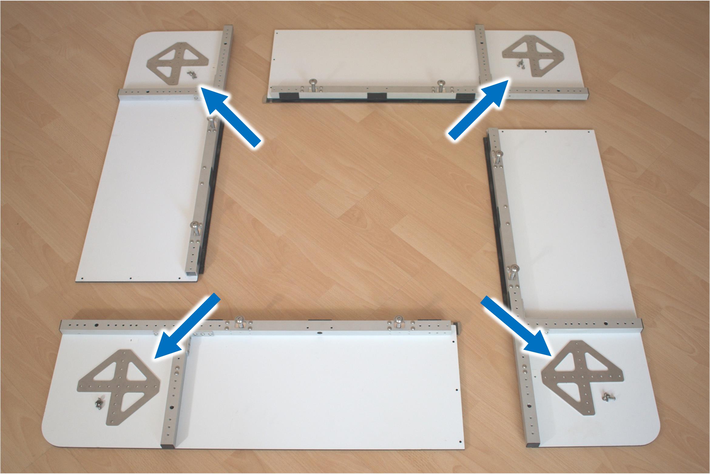
Each baffle panel has a corner plate pre-installed. Unmount these parts at first. This will simplify the next assembly steps.
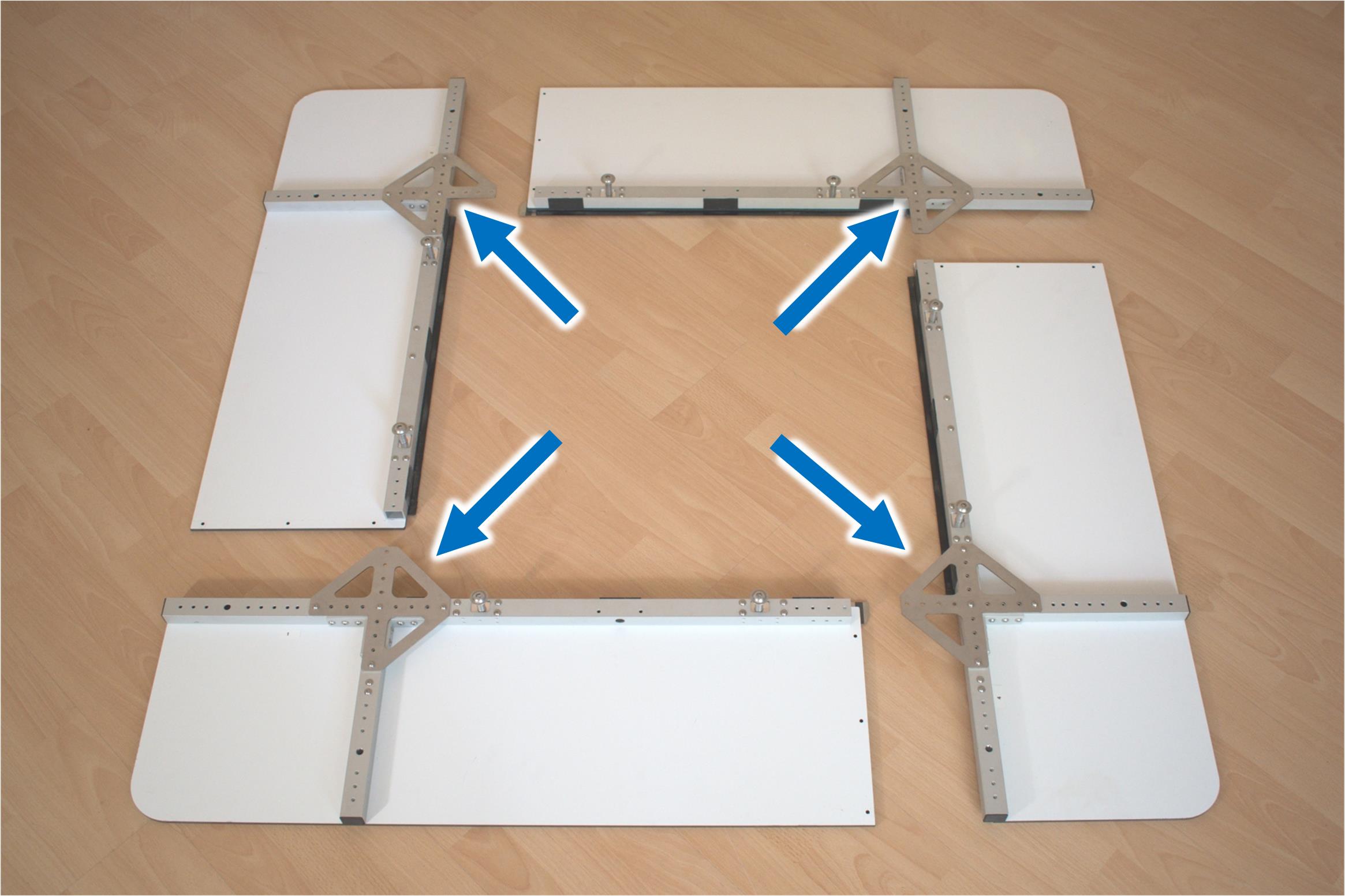
Put the corner plates and the M4 panhead screws next to the mounting position. These parts are needed soon.
Shift Panels Together#
Instructions#
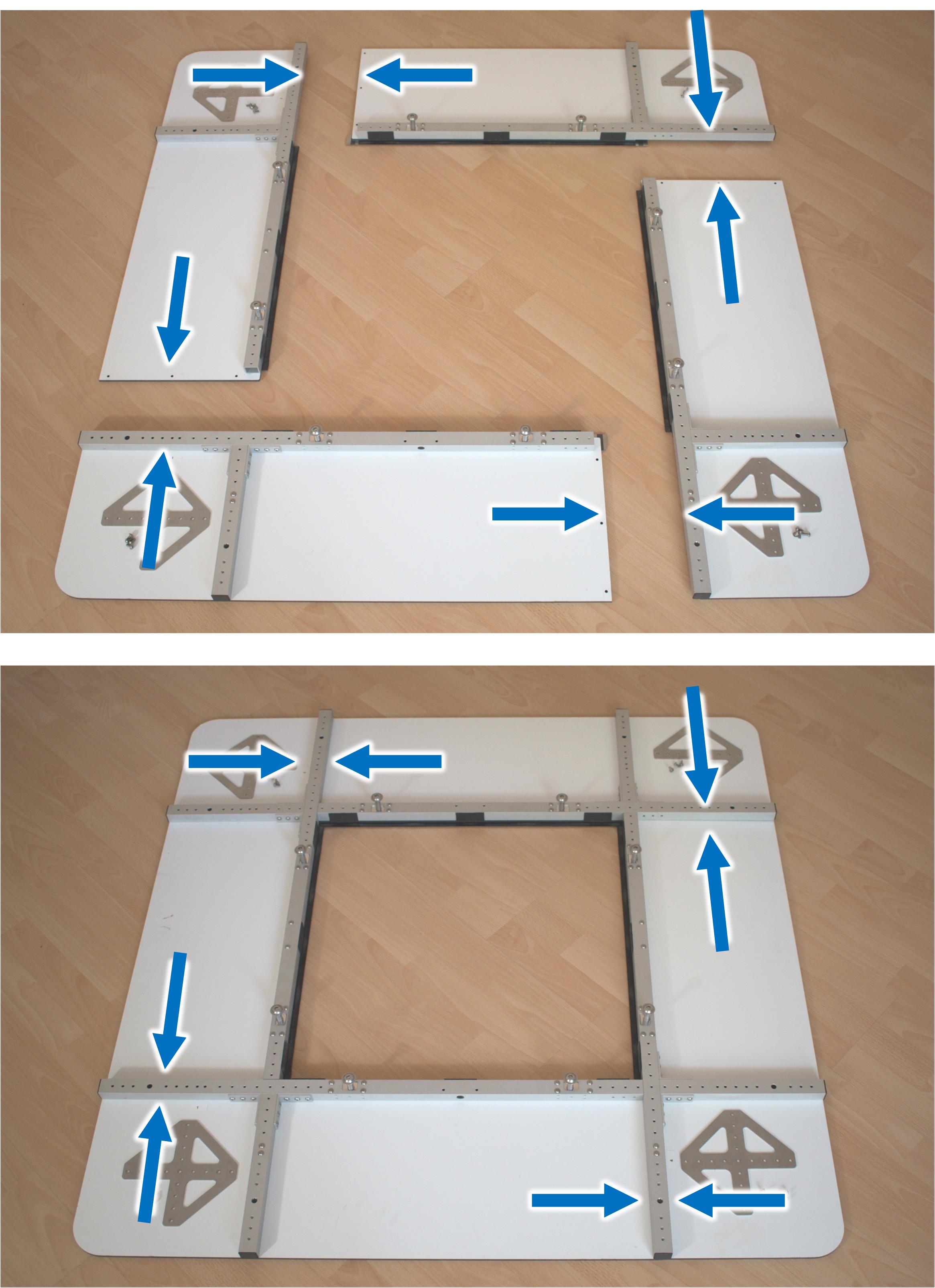
Push the 4 baffle panels together. Ensure the profile fit close together without a large gap.
Checks Position of Panels#
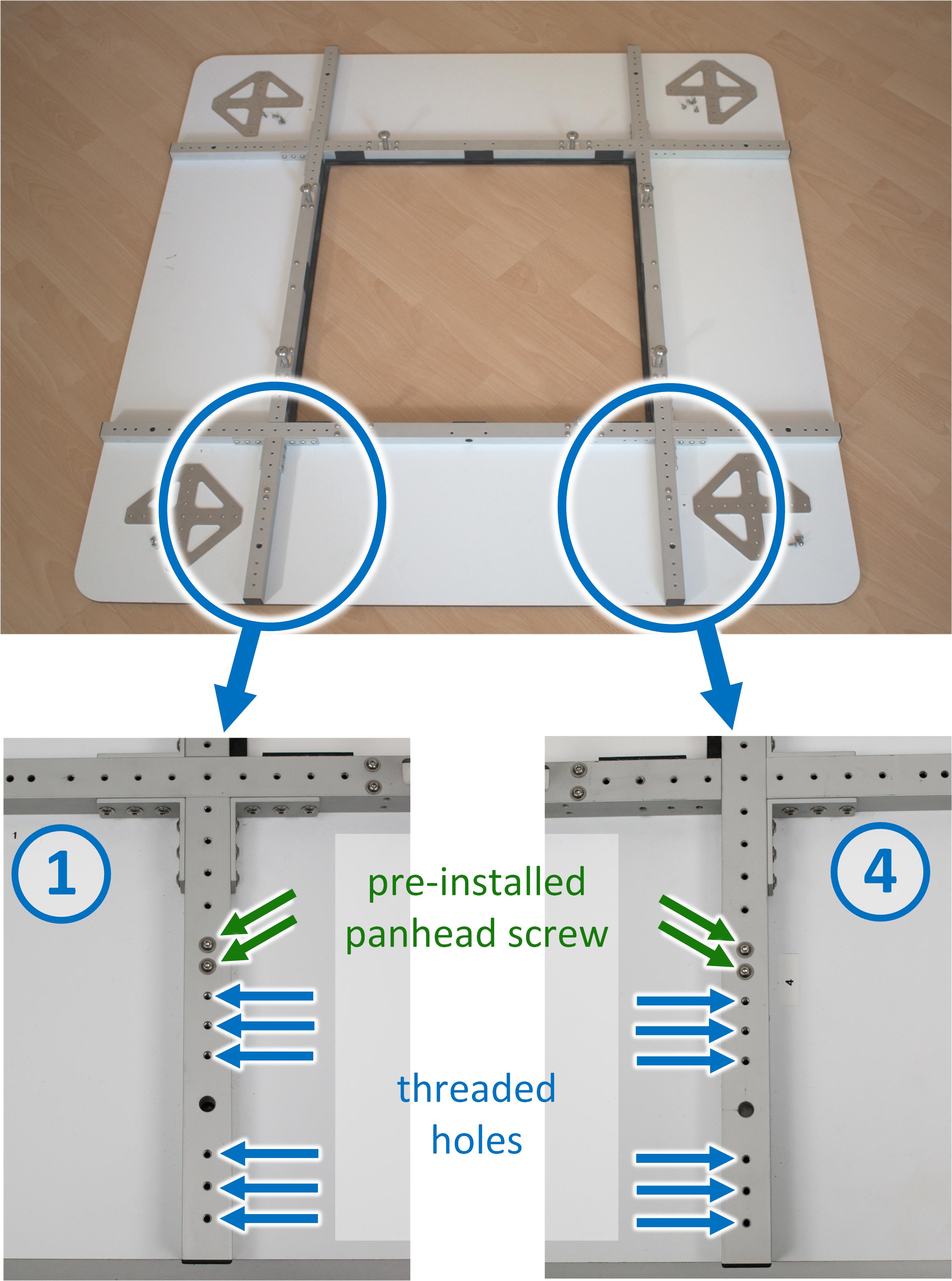
Double check the position of the panels. Each of the two profiles on the bottom must have 2 pre-installed panhead screws and 6 threaded holes. If this is not the case, please go back to step Placement of Panels and put the panels into the correct order.
Mount Small Brackets#
Parts#
- 2.5 small bracket - 19 mm
- Quantity: 4
- 2.4 panhead screw M4x10 mm
- Quantity: 24
Instructions#
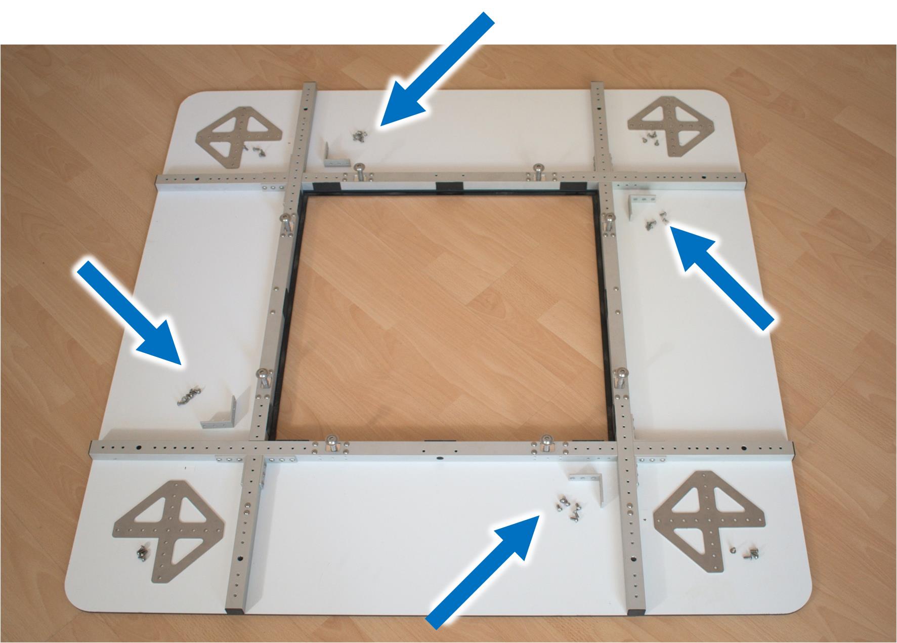
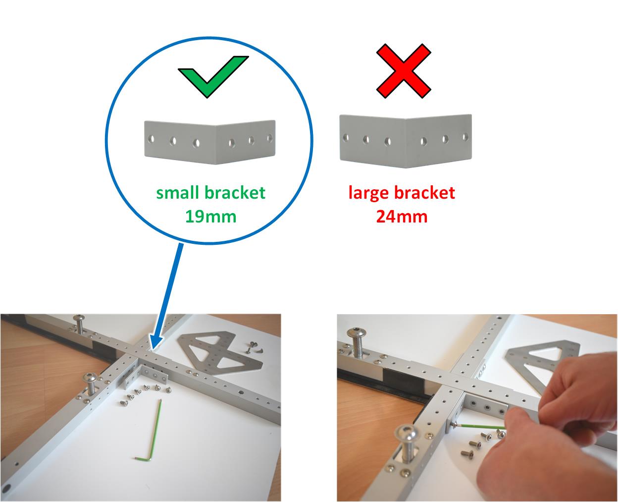
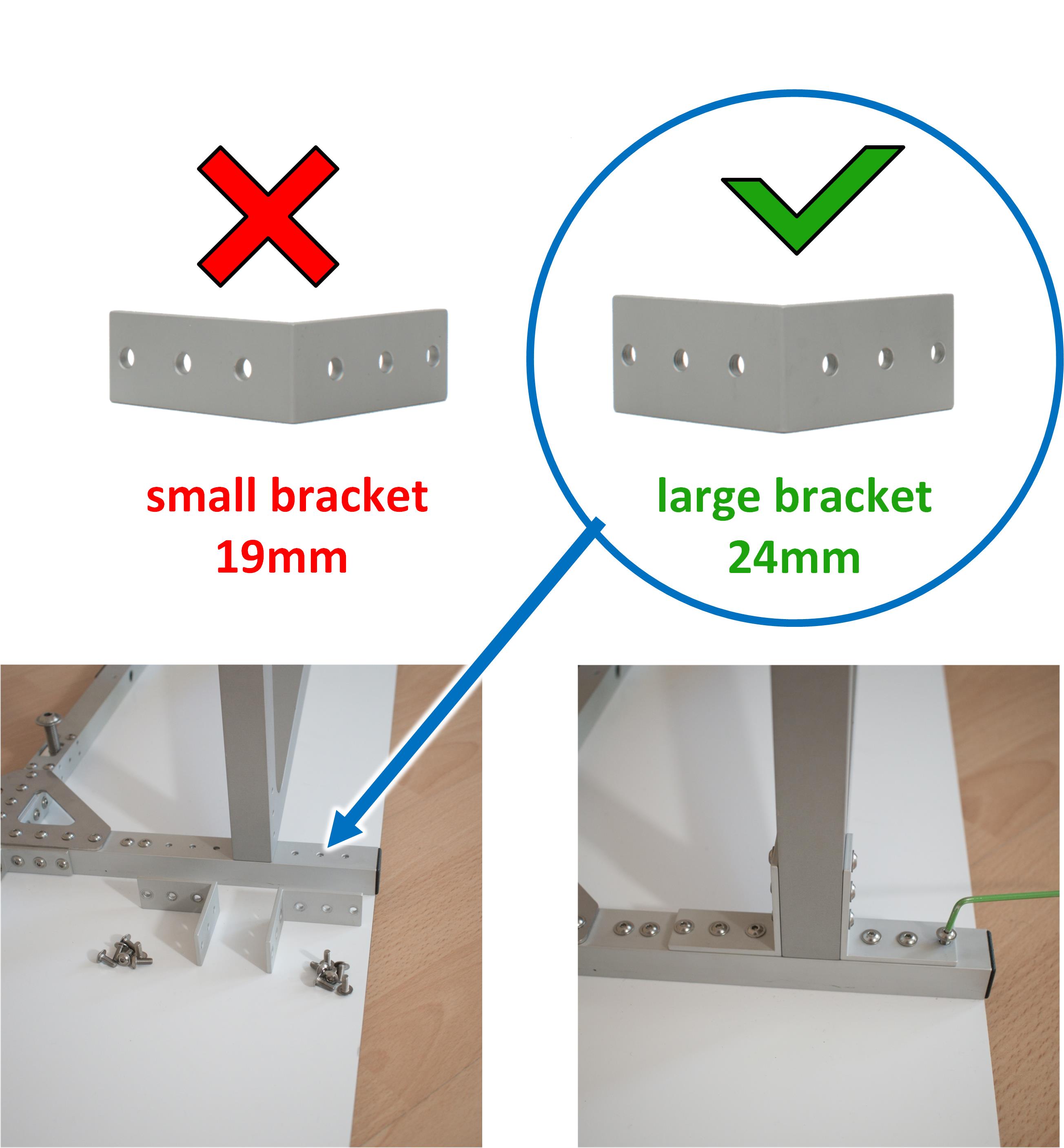
Use the small brackets to screw the baffle panels together. Each bracket is mounted with 6 M4 screws. Make sure the small brackets are used!
Mount Corner Plates#
Parts#
- 2.4 panhead screw M4x10 mm
- Quantity: 84
Instructions#
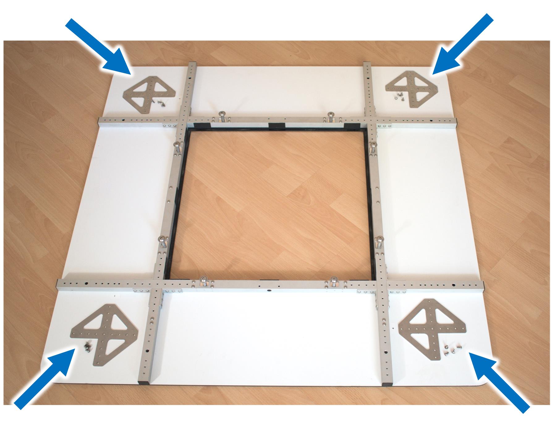
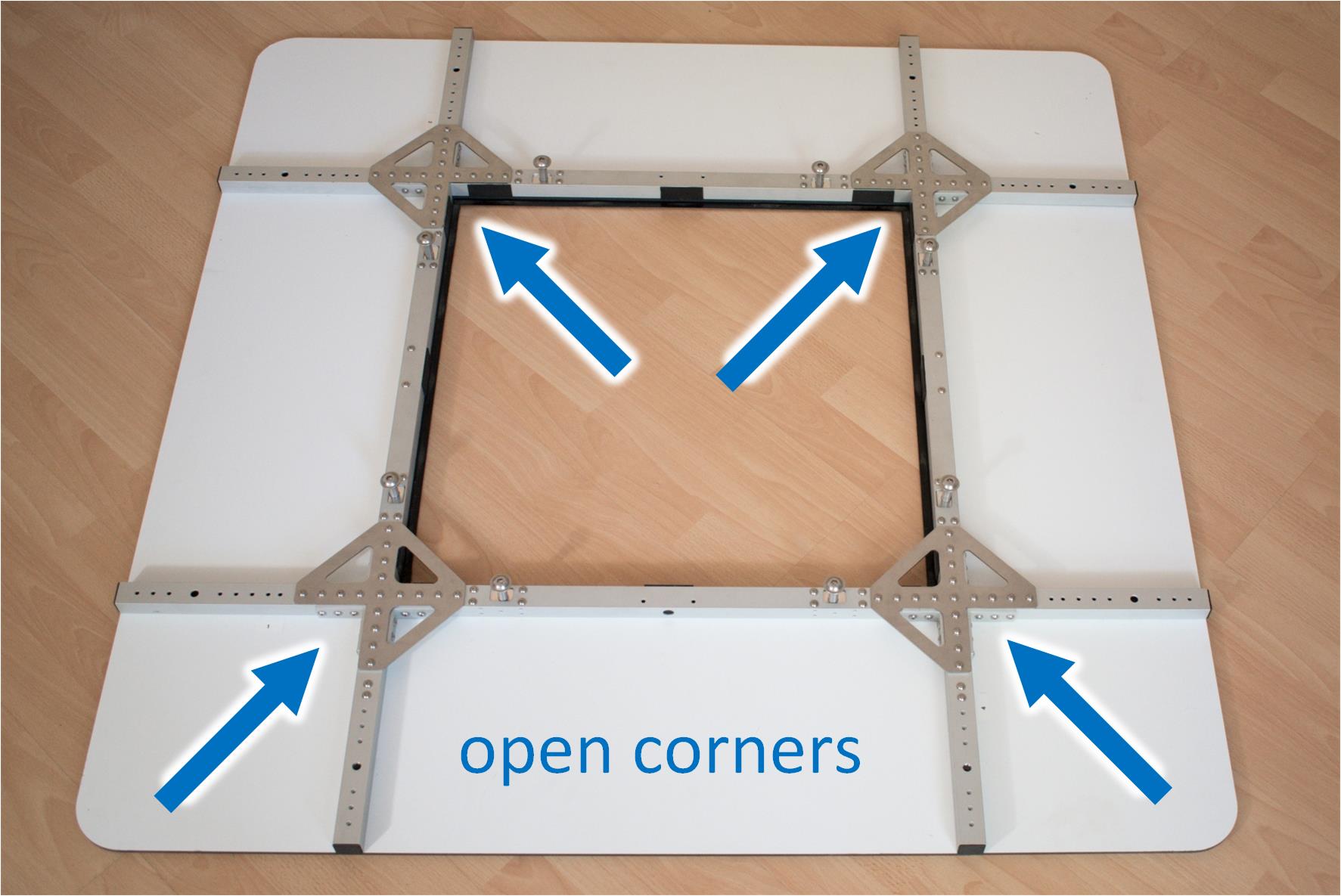
Use the panhead head screws to attach the 4 corner plates.
Make sure the open corner are at the following positions.
Connect Base Plate#
Parts#
- 1 base plate
- Quantity: 1
Instructions#
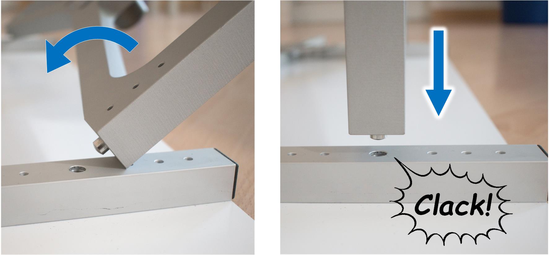
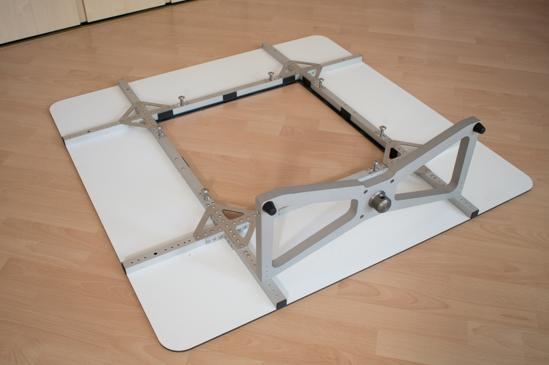
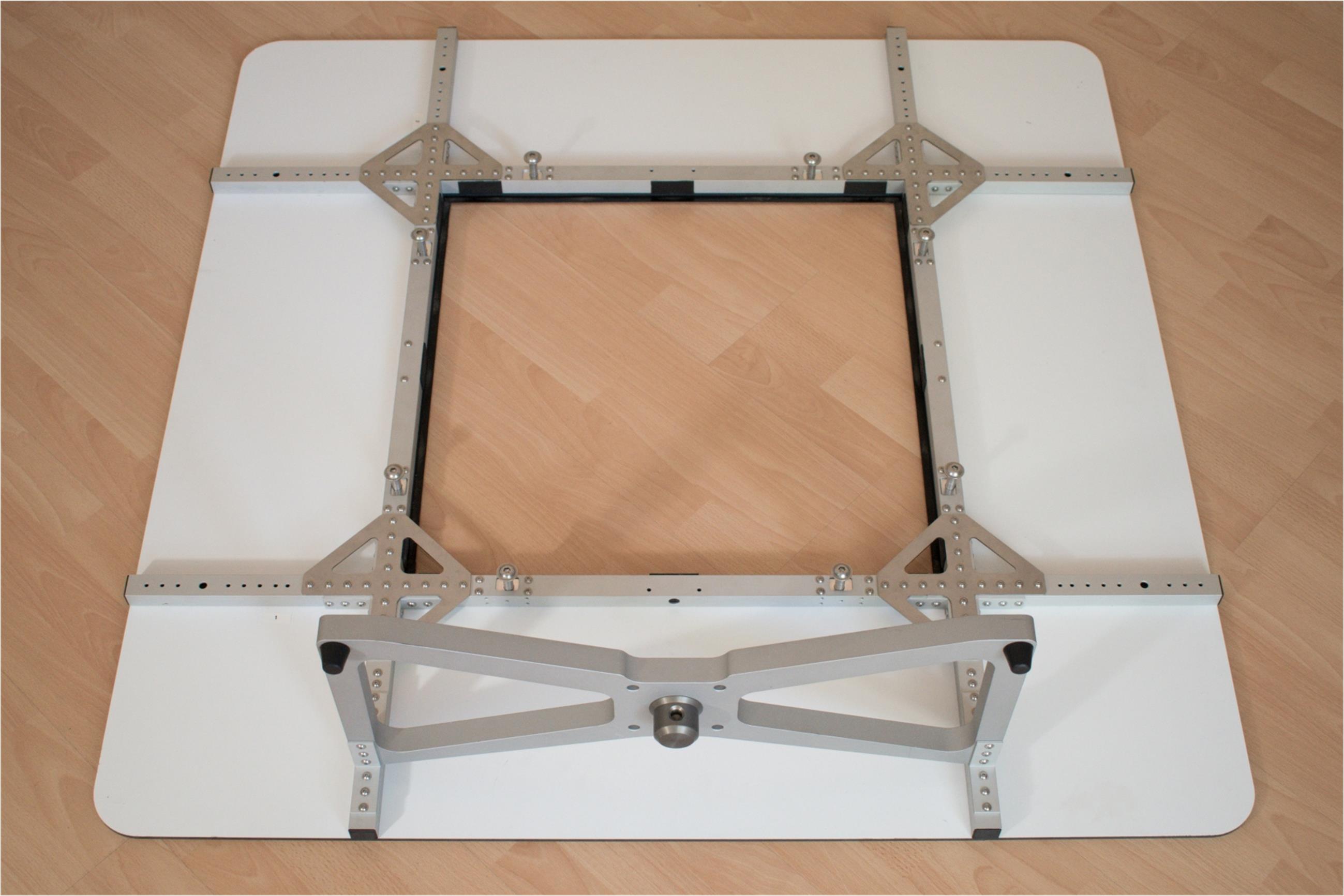
Attach the base plate to the baffle by inserting the bolt of the base plate into large holes of the baffle profiles. Once it is properly attached, you can hear a “clack”.
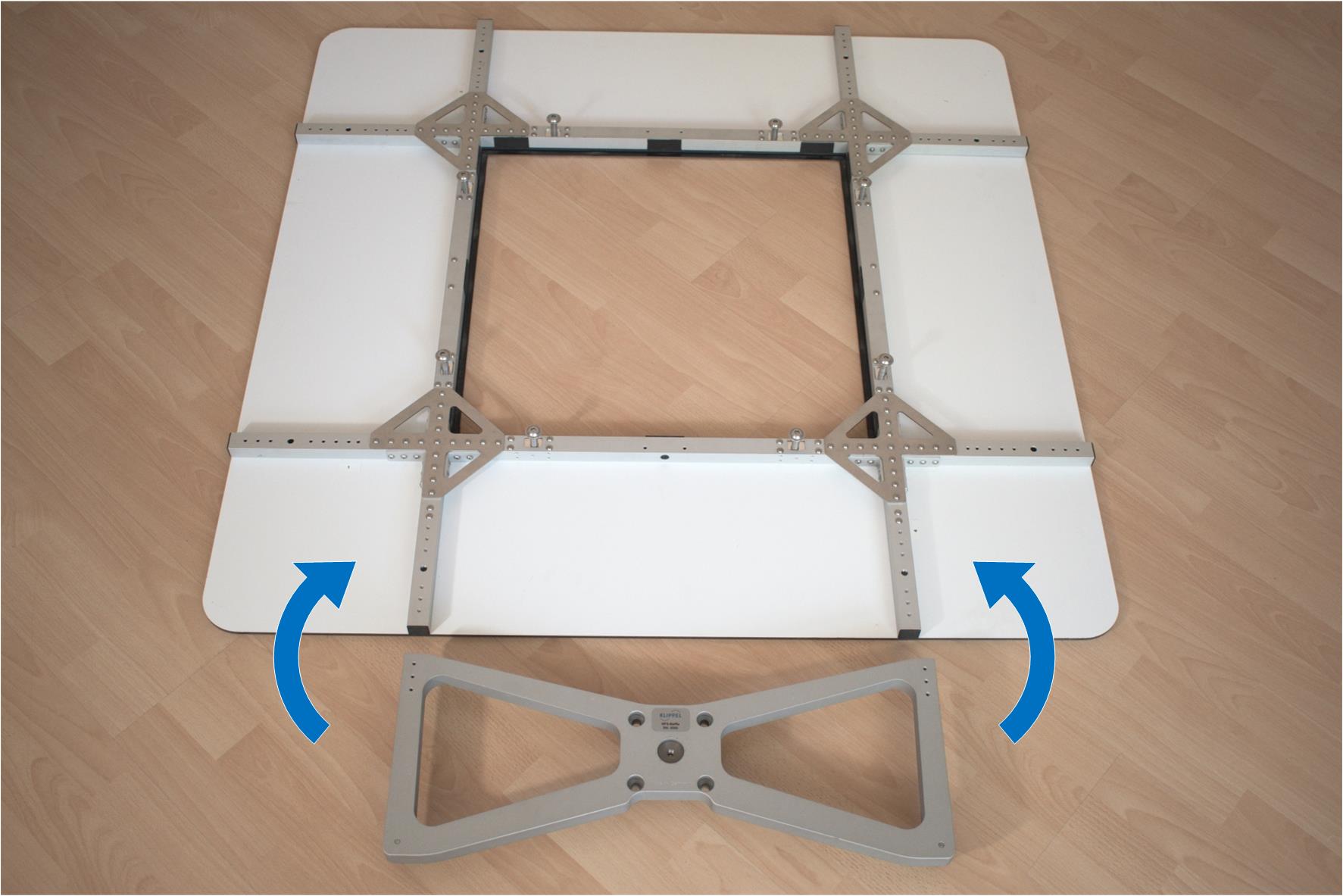
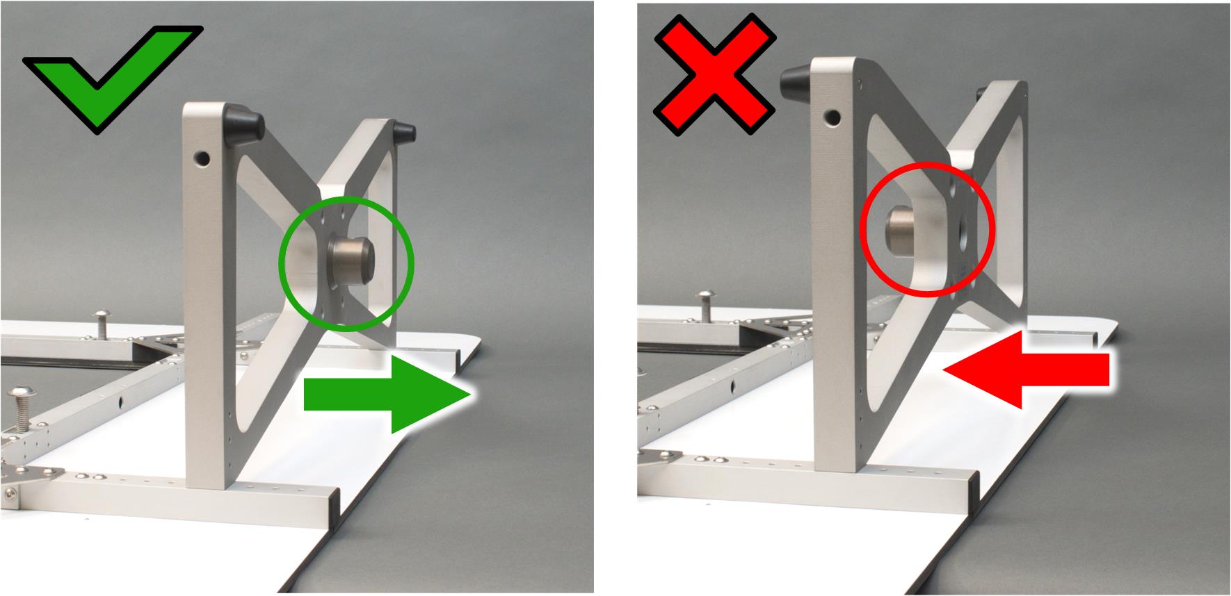
Make sure, the feet and the connection shaft of the base plate are pointing to the outside.
Mount Large Brackets#
Parts#
- 1.6 large bracket - 24 mm
- Quantity: 4
- 2.4 panhead screw M4x10 mm
- Quantity: 24
Instructions#
Secure the base plate with the large brackets. Each bracket is mounted with 6 M4 panhead screws.
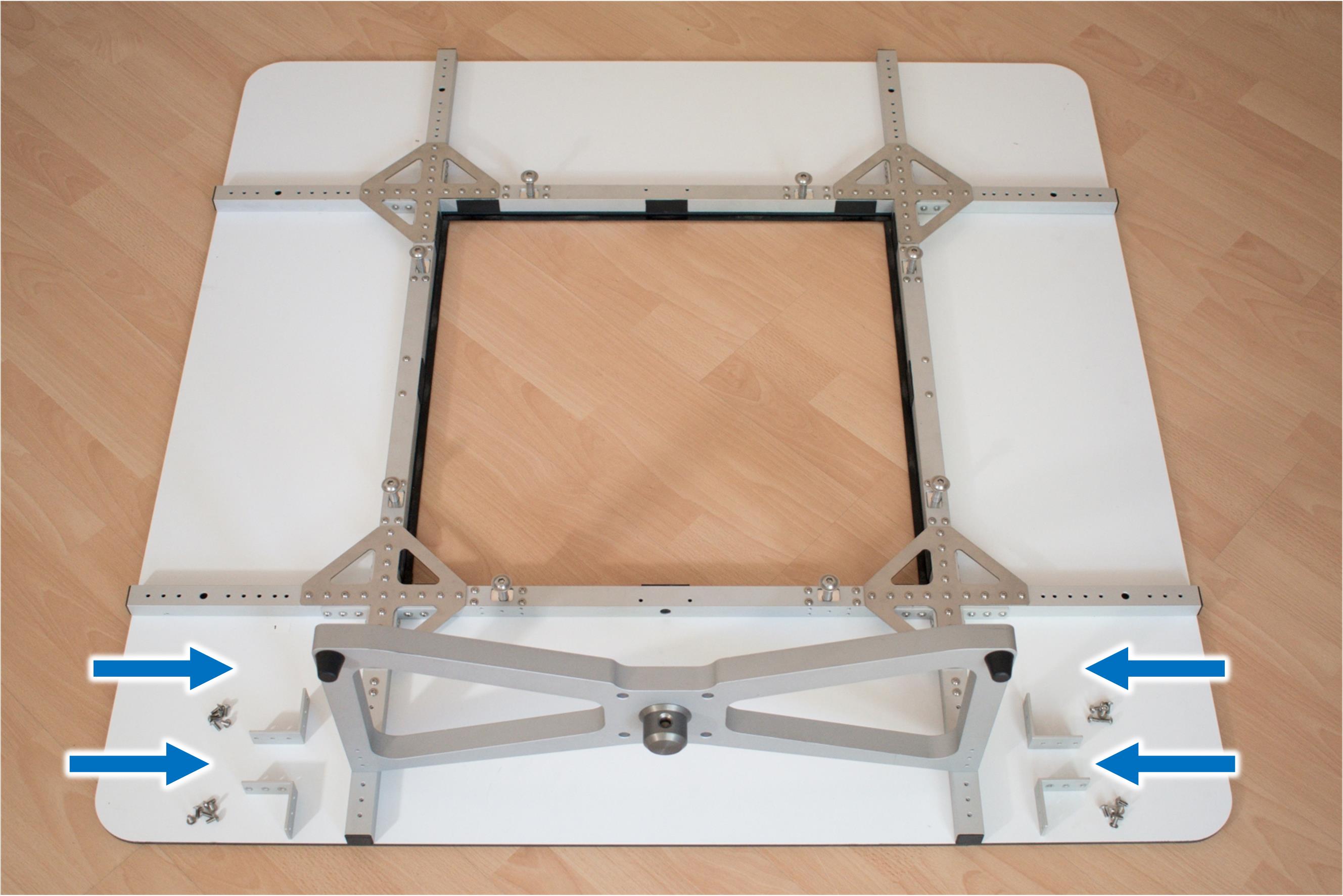
Make sure the large brackets are used.
Mount Struts#
Parts#
- 3 + 4 struts left/right
- Quantity: 2
- 1.4 cylinder head - M10x30 mm
- Quantity: 4
Instructions#
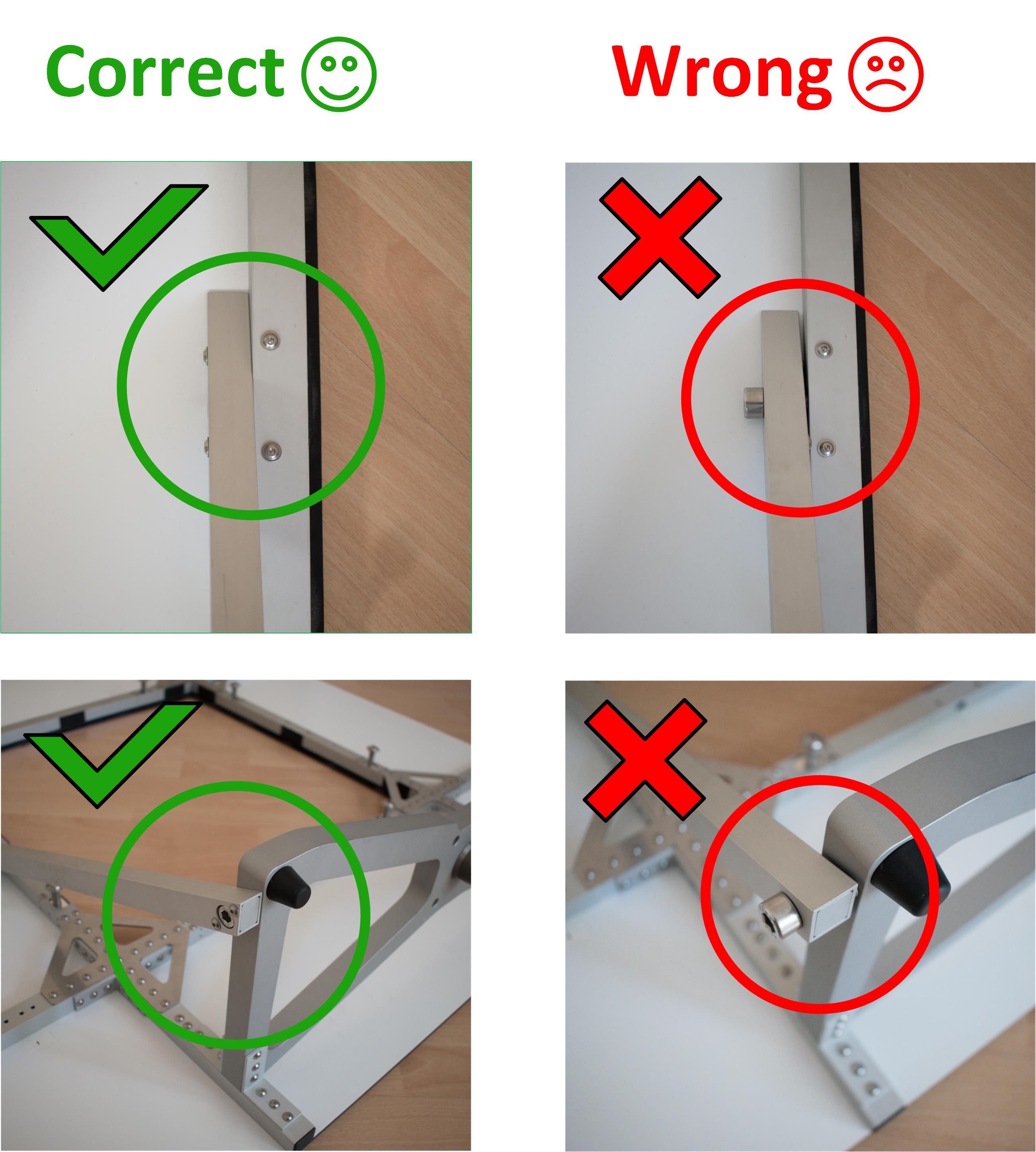
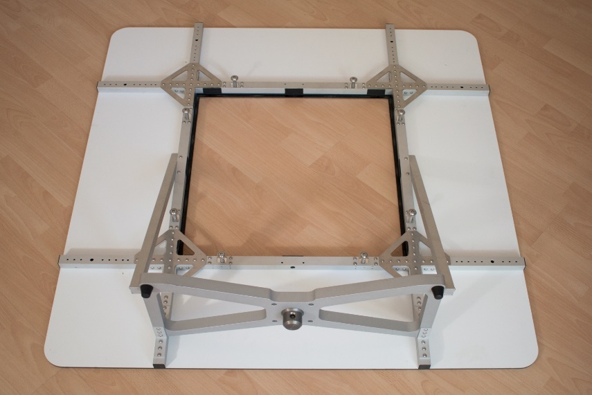
Bolt the left and right strut with the M10 cylinder head screws to the baffle profiles and the base plate
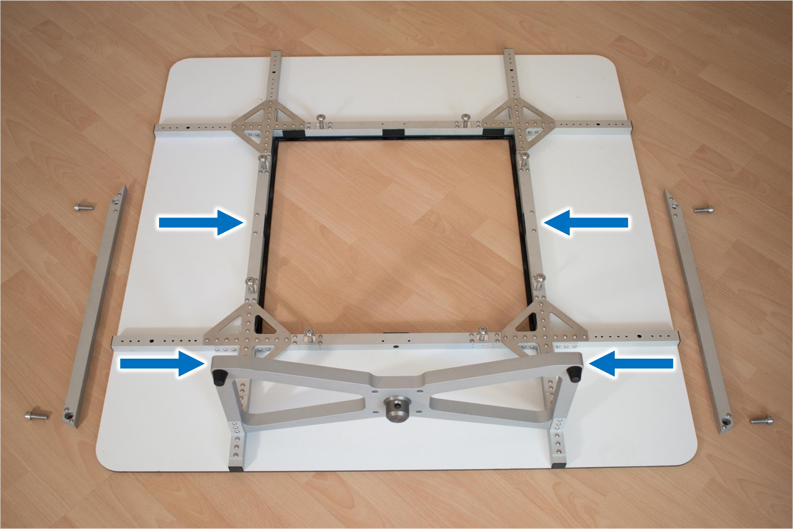
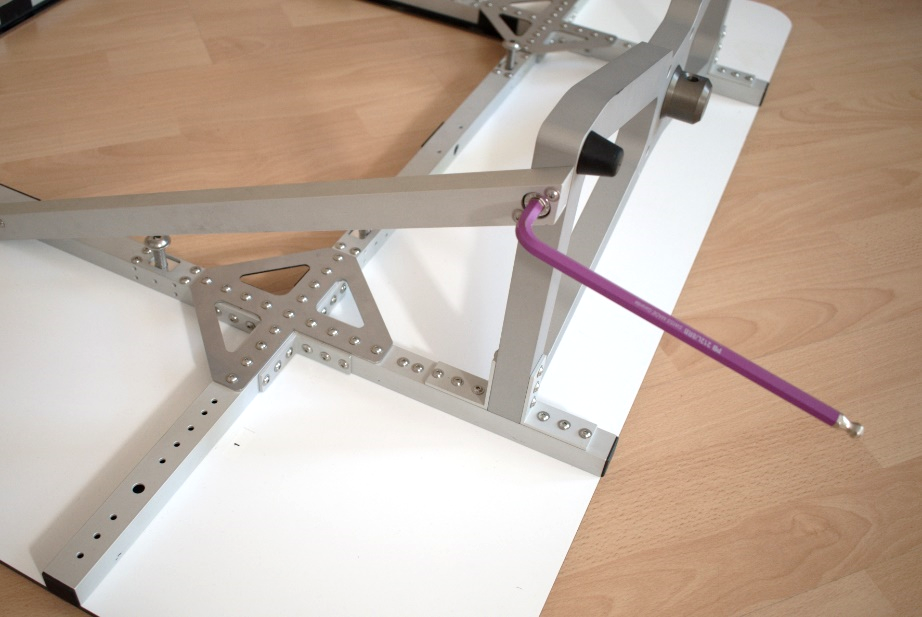
Make sure that the M10 cylinder head screws fit into the counter bores of the struts. If this is not the case, interchange the profiles.
Mount Remaining Screws#
Parts#
- 2.4 panhead screw M4x10 mm
- Quantity: 12
Instructions#
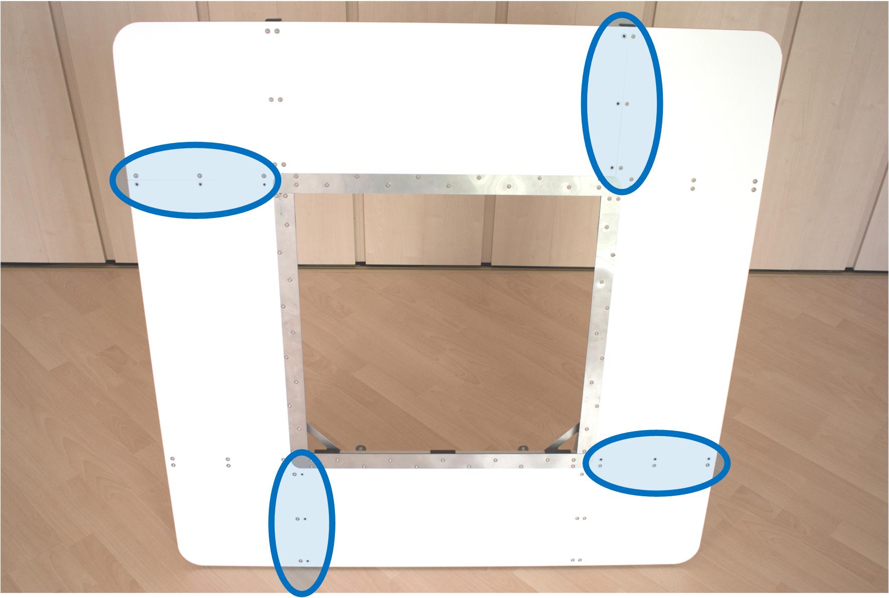
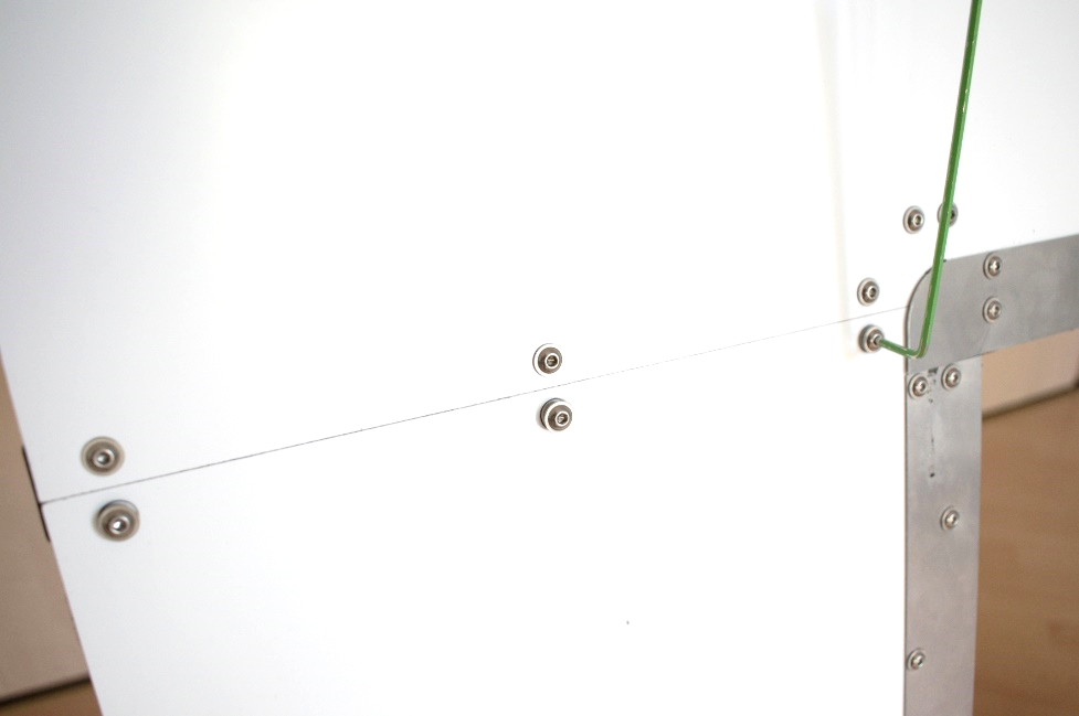
Place the baffle upright. At the 4 connection edges of the panels, there are 12 M4 screws missing, that needs to mount.
Assembly Finished#
Once the assembly is finished, please double check that all screws are tight. Loose screws can cause audible rattling.
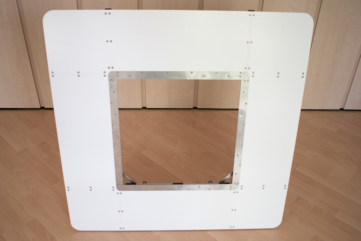
Mounting on Near Field Scanner#
Remove Adapter Plate#
Instructions#
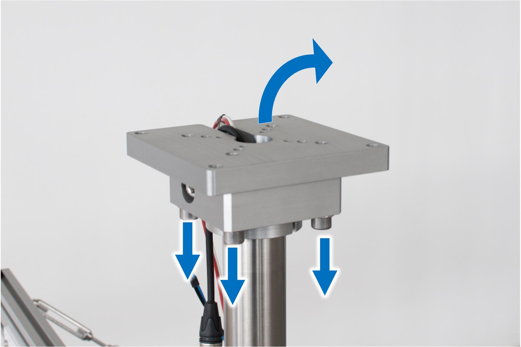
To mount the NFS Baffle on the Near Field Scanner Hardware, the adapter plate needs to be removed from the flange. Unscrew the 4 M10 screws, but keep them nearby.
Mount Flange Adapter#
Parts#
- 1.9 flange adapter
- Quantity: 1
- cyinder head screw + washers (from NFS)
- Quantity: 4
Instructions#
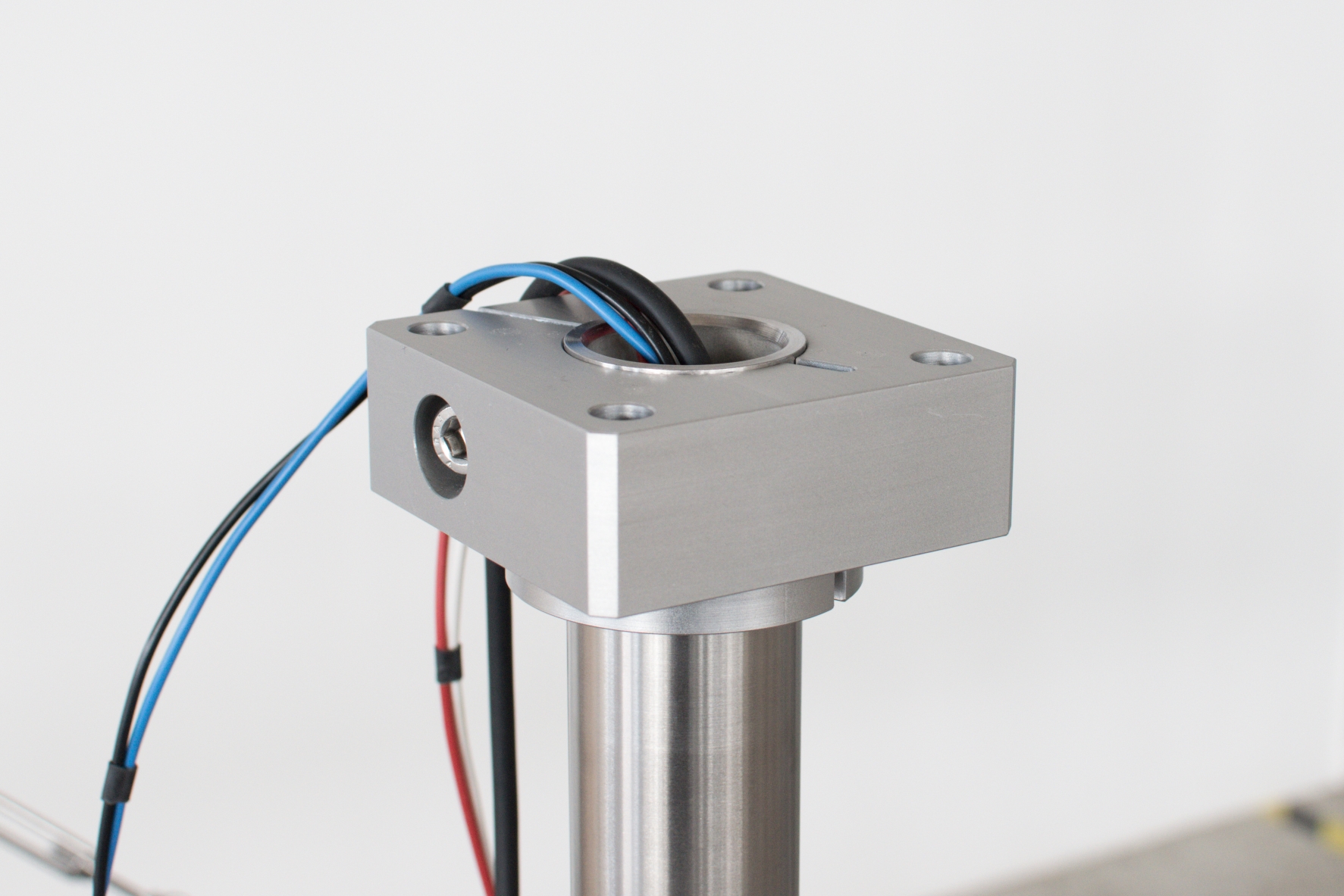
Use the M10 screws and washers from the Near Field Scanner to bolt the flange adapter to the flange. Make sure all cables go through the side holes of the flange adapter.
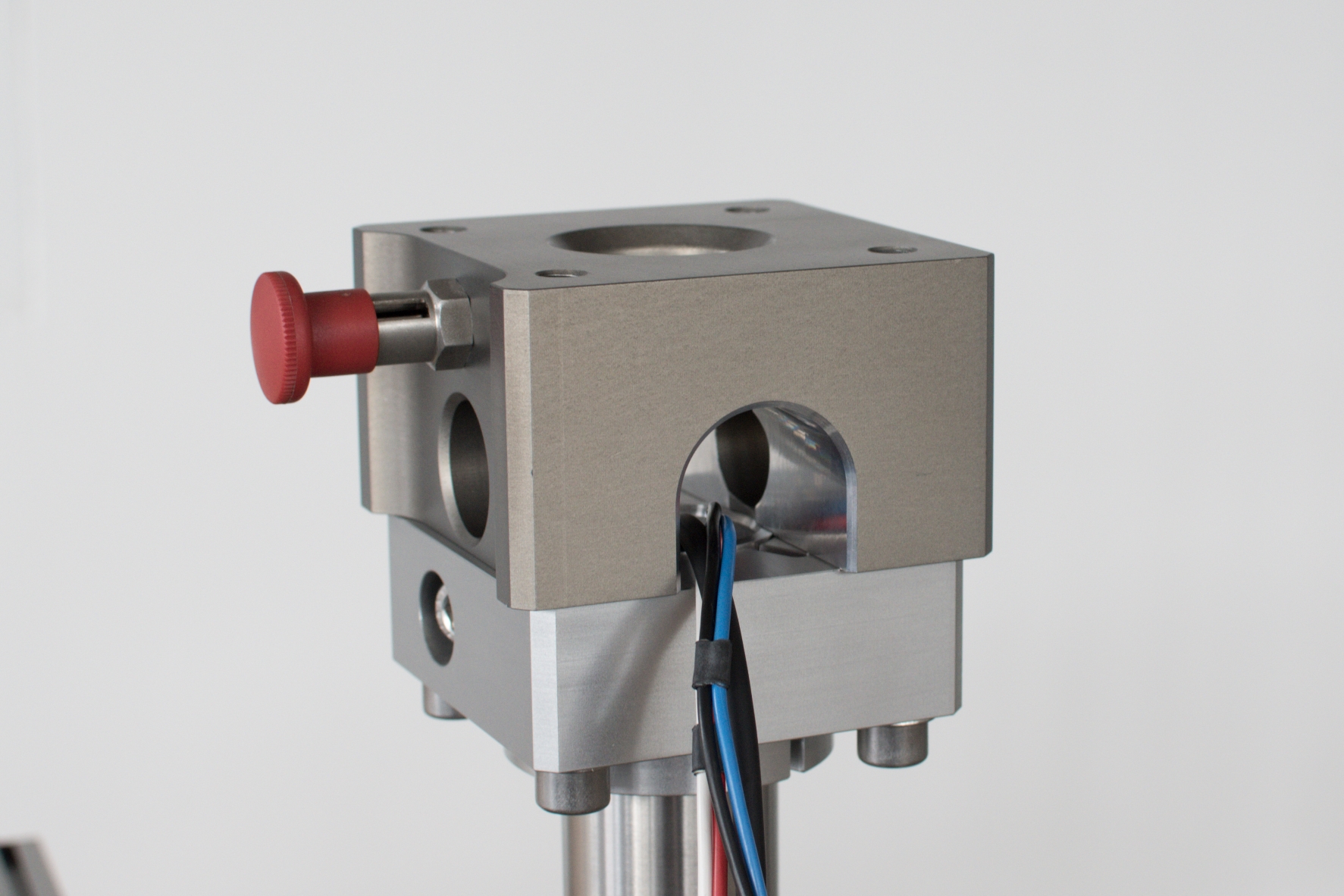
Unlock Flange Adapter#
Instructions#
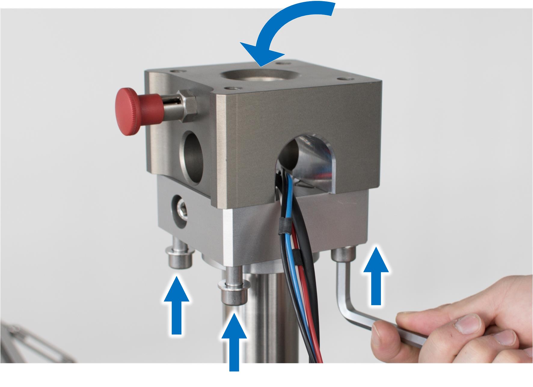
The flange adapter has a fast locking mechanism. Before the baffle can be mounted, this locking bolt needs to be released. Move the bolt outwards and rotate the red knob to unlock.
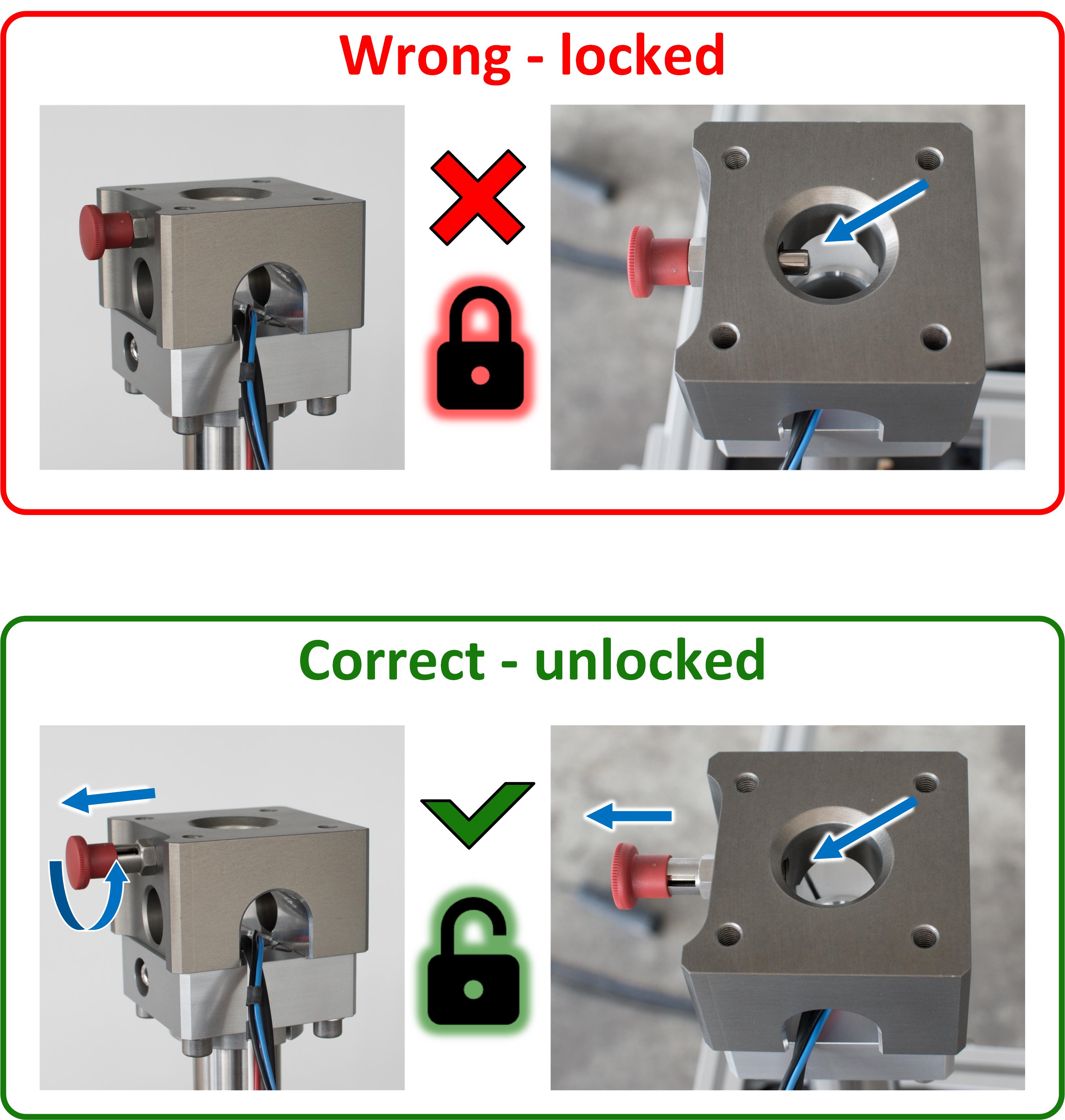
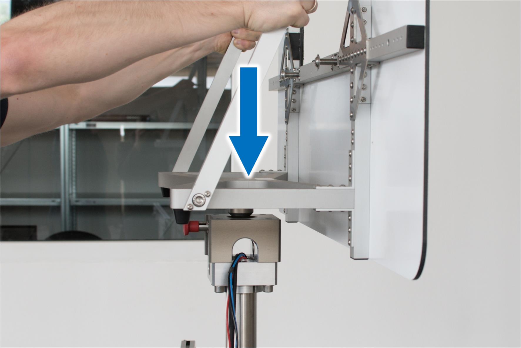
Mount Baffle#
Parts#
- 1.4 cylinder head screw - M10x30 mm
- Quantity: 4
Instructions#
Put the Baffle on the Near Field Scanner. The shaft of the baffle base plate needs to be inserted in the center of the flange adapter.
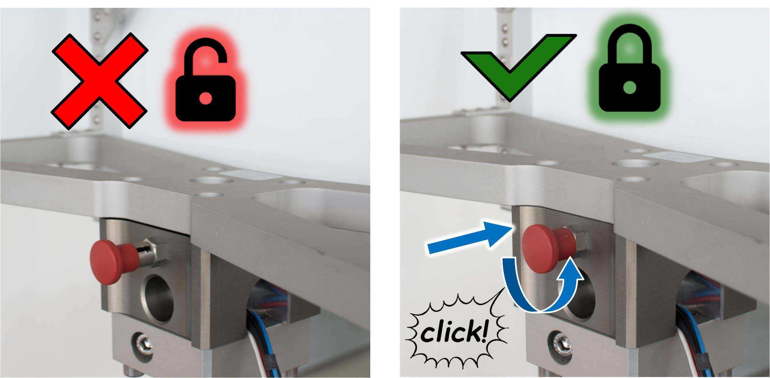
Rotate the red knob and the base plate until the bolt skips in and locks.
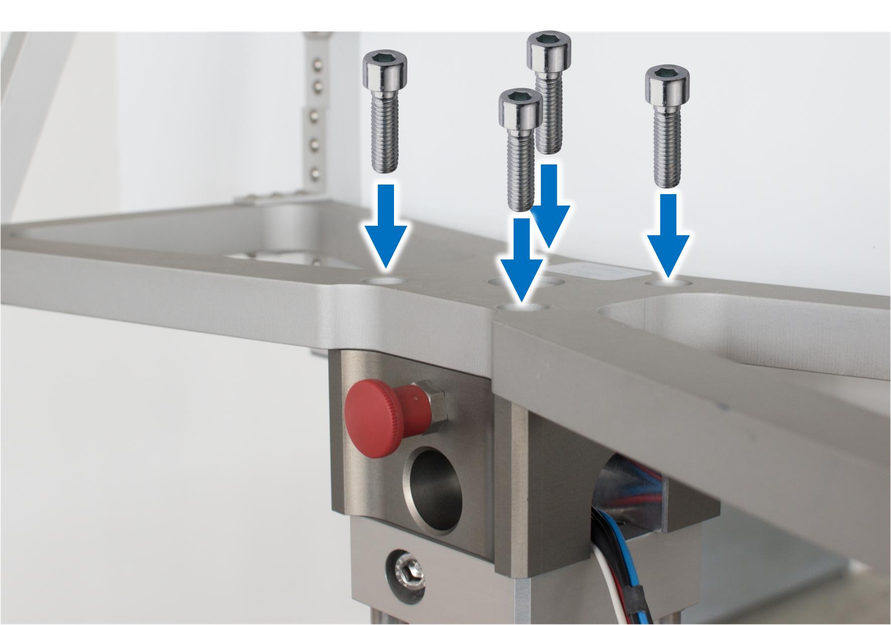
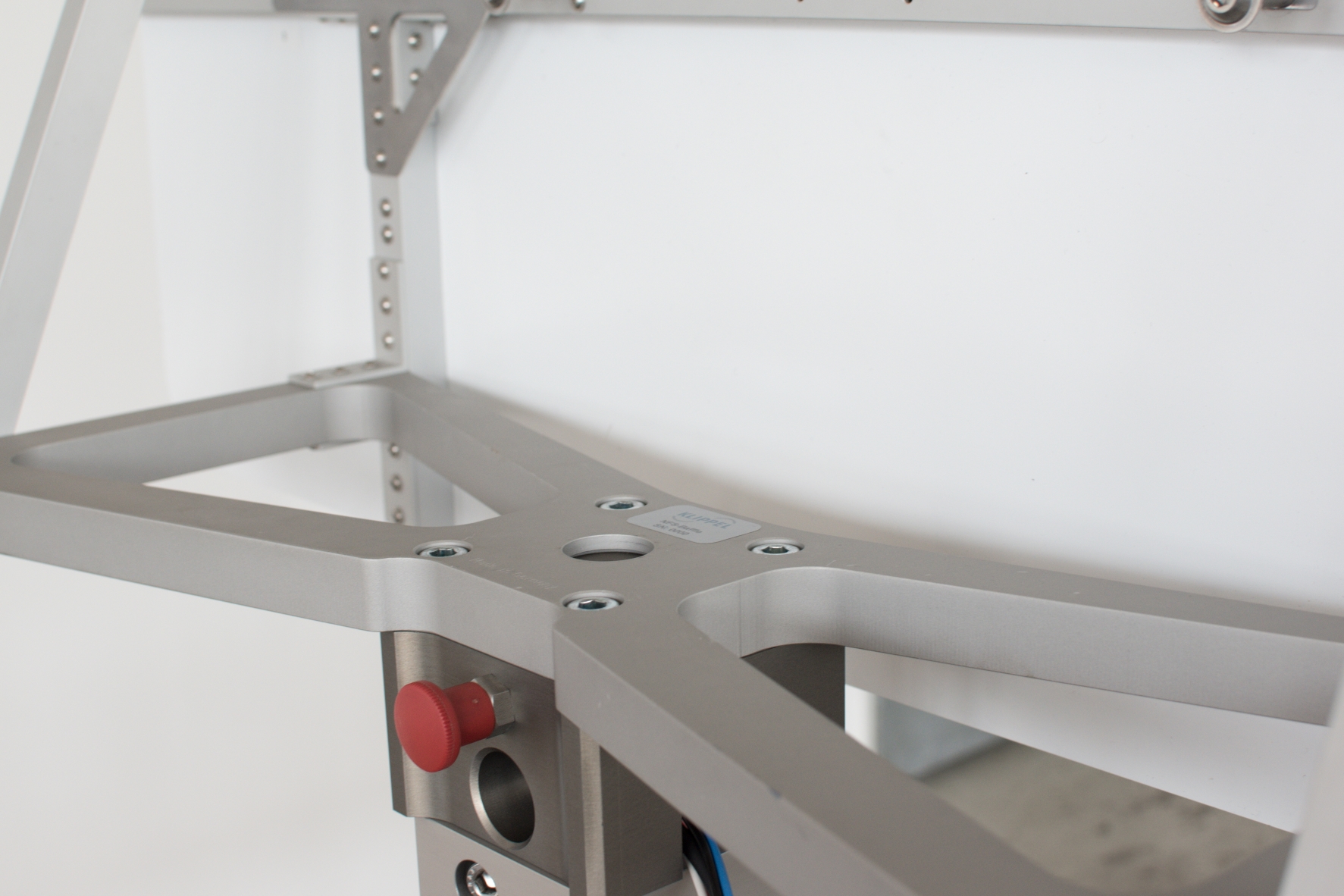
Secure the baffle with 4 M10 cylinder head screws.
Transducer Plate#
The transducer plate is not included in the NFS Baffle Hardware package. This is a custom made part for each transducer. The plate should be 545x545mm.
Note
Mounting thicker plates is also possible.
Mechanical vibration of the transducer plate are critical for the measurement, because this will affect the accuracy of the measurement results. Maybe addition damping needs to be attached. This can be done at the backside of the plate.
Insert Transducer Plate#
Instructions#
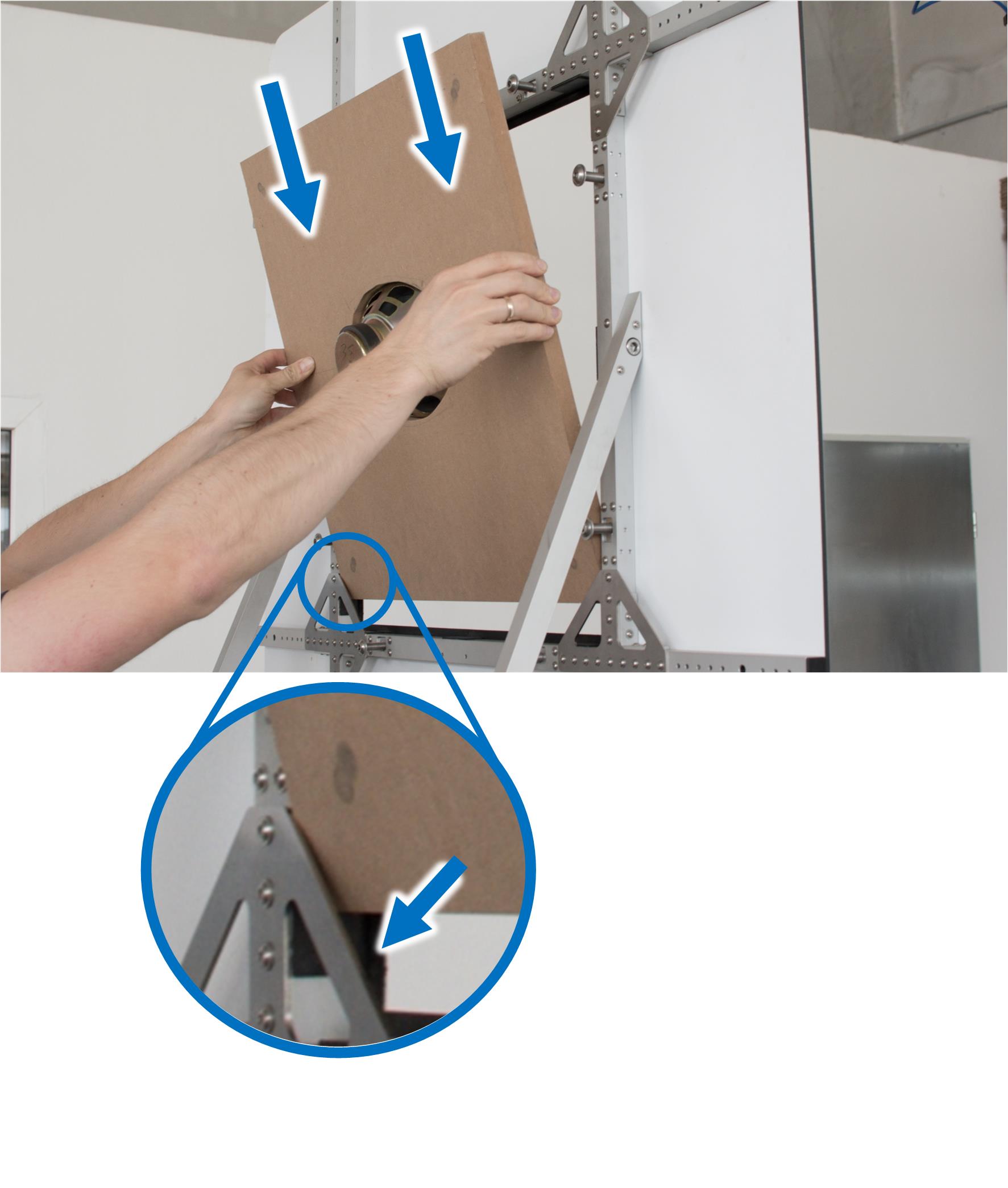
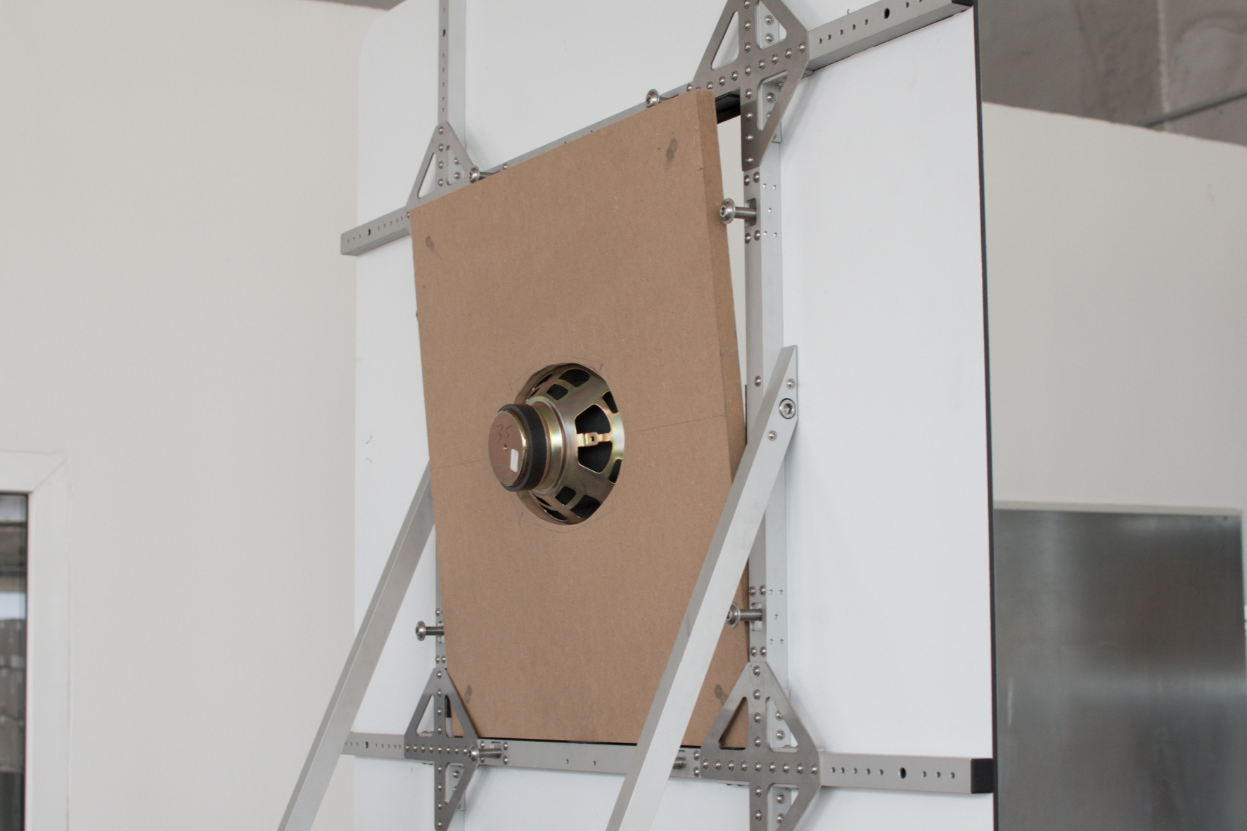
The transducer plate is mounted from the backside. Shift the plate behind the edges of the lower corner plates. This secures the plate from falling out.
Add Tensioners#
Parts#
- 5 tensioner
- Quantity: 4
- 8.1 wrench - 8 mm
- Quantity: 1
Instructions#
The transducer plate need to be clamped by the tensioner. Mount the upper tensioners at first.
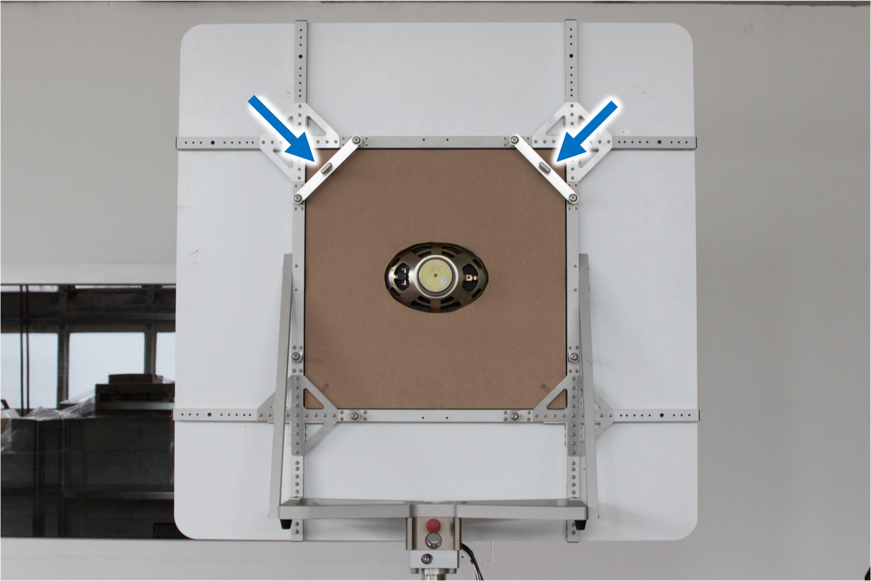
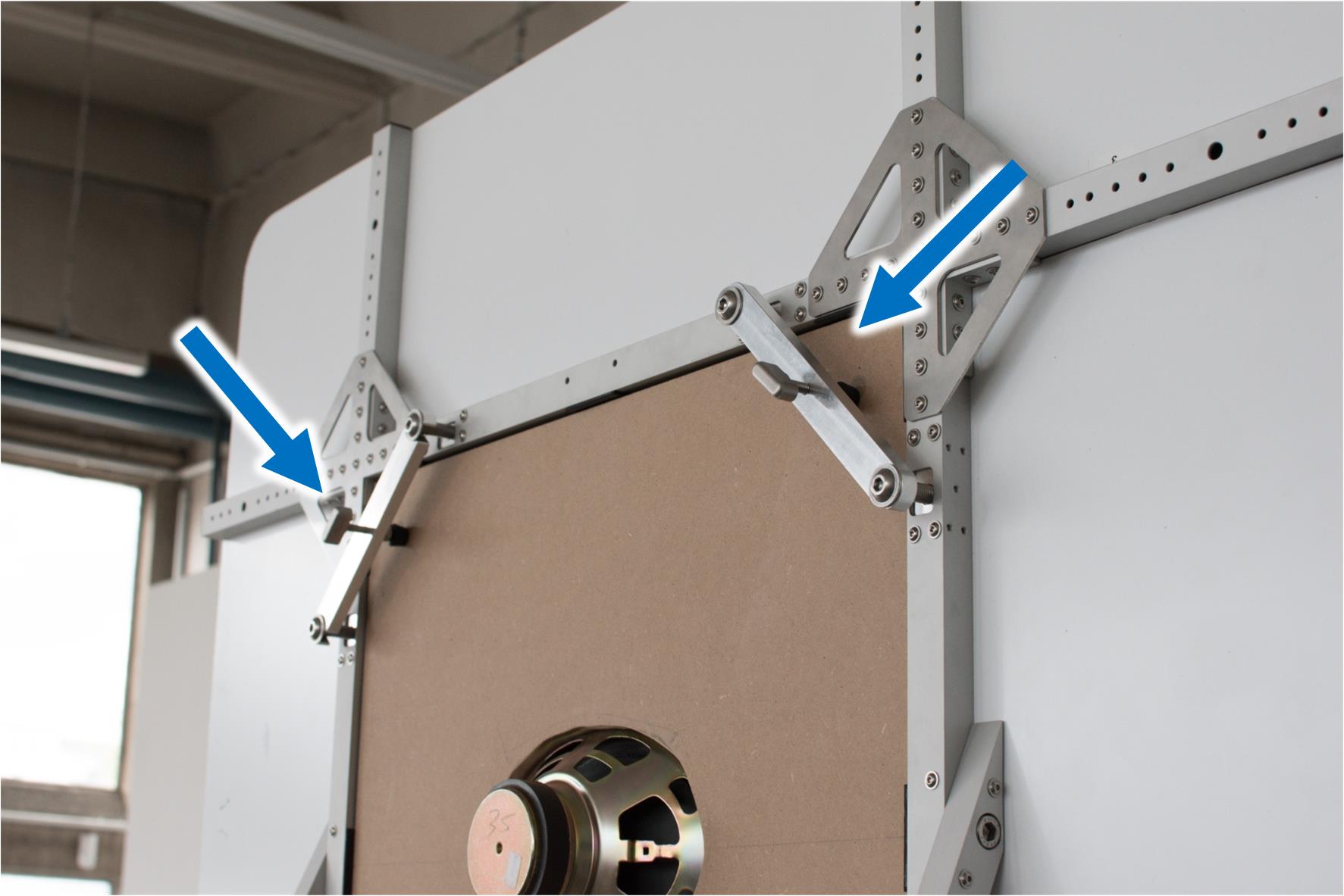
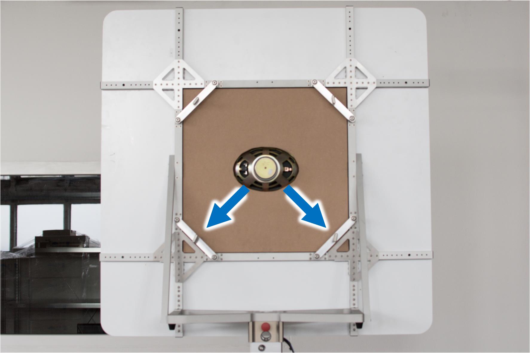
Once the upper tensioners are fixed, mount the lower tensioners as well.
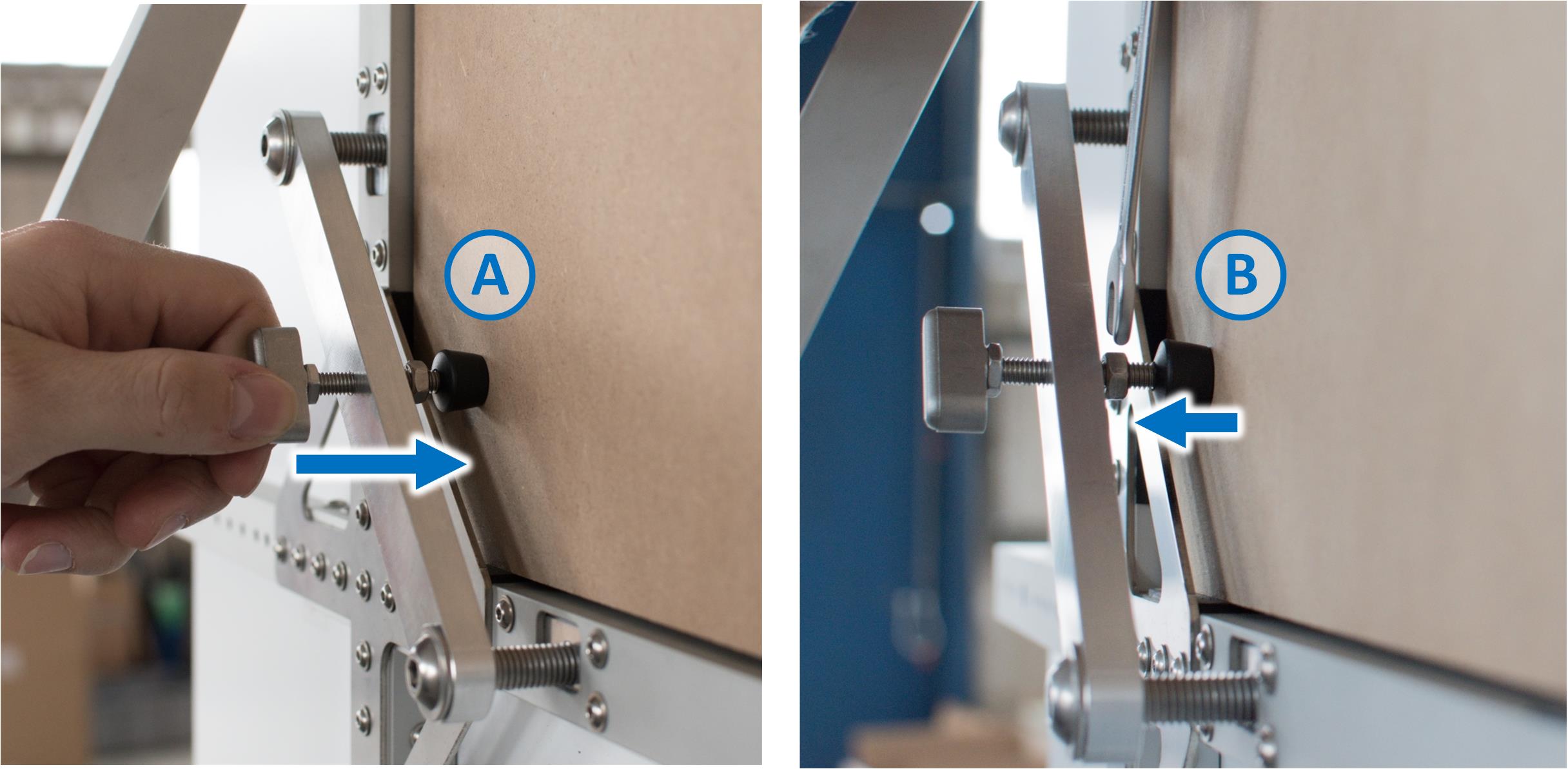
Tight the all tensioners by hand (A). Then use the wrench to counter each screw with a nut (B).
Mounting Completed#
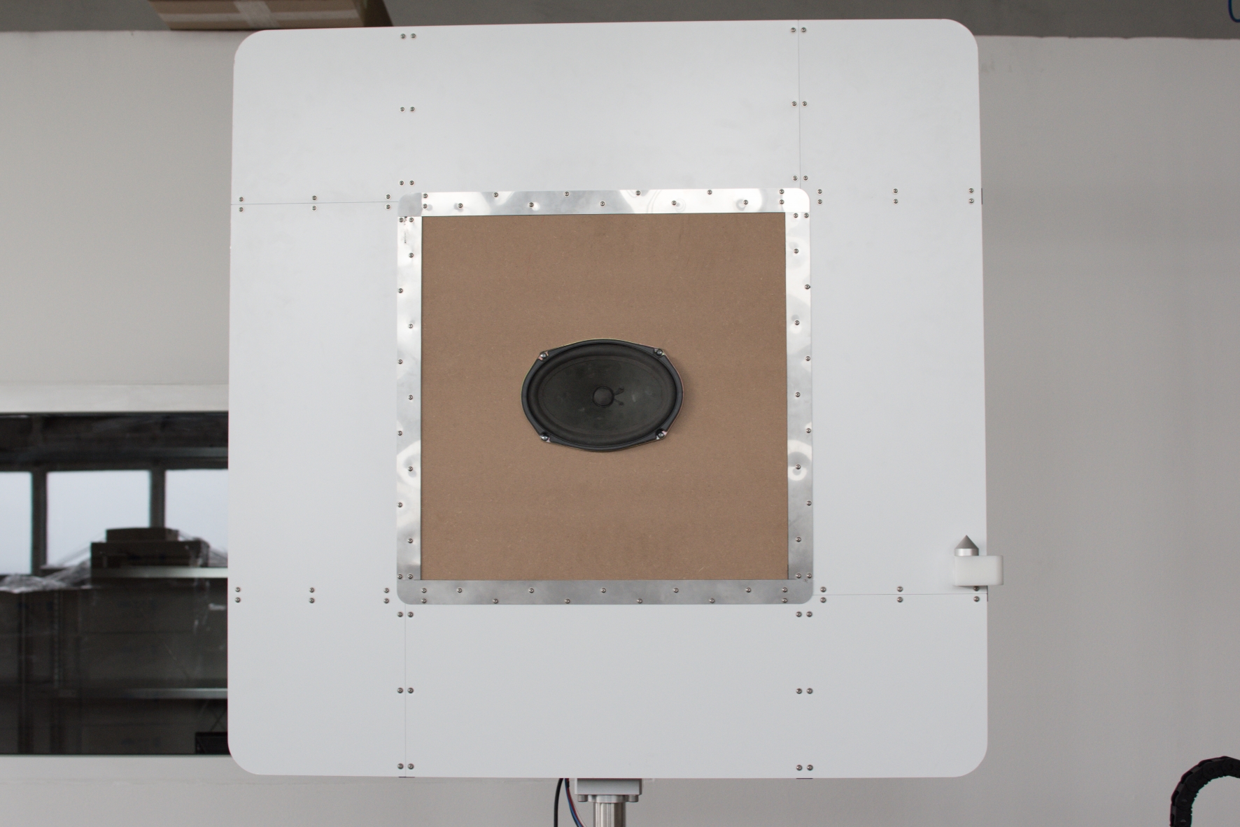
Once the transducer plate with the device under test is mounted the hardware is ready for a measurement.
A detailed description of the measurement procedure is included in the NFS Software Manual. Please see Tutorial Part 4: Half Space Measurement.
