SCN-NF – SCN Near Field Add-On#
SCN NF - Safety Instructions#
English: Instructions for Operation#
Operation of the machine is restricted to authorized personnel only.
Authorized personnel are required to:
read, understand and follow all instructions in the “R&D System User’s Guide SCN Near Field Add-On” and “SCN Near Field Add-On Mounting Instruction”
follow all instructions given in Safety Instructions.
KLIPPEL is not liable for any damage or injury caused by disregard of the safety instructions or any instruction in the manual.
Automated operation#
Ensure no personnel is in the area where the machine is moving (automated or manual movement).
Make sure the Emergency-Stop is in reach of the operator when operating the machine.
General#
Make sure that the SCN Near Field Add-On Hardware is set up in a separate room or separated area, so an acoustic level of 80 dB SPL is not exceeded at any nearby workplace.
During operation with high sound pressure levels (above 80 dB SPL), operators must wear proper ear protection at any time.
Do not modify the machine. Use original cables, power supply and assembly parts only. Do not modify or repair KLIPPEL hardware or accessories without proper instruction by KLIPPEL!
Make sure the power socket used to power the hardware provides an adequate overcurrent protection.
All personnel operating the SCN Near Field Add-On must be regularly briefed about the residual hazards of the SCN hardware, as shown in the list below.
Danger of crushing. Keep a safe distance when moving any axis. Placing any limb in the moving range of the machine may lead to injury. Allow for quick access to the emergency stop switch on the Z-Axis of the SCN and on the Motor Control Unit.
German: Anweisungen für die Bedienung#
Der Betreiber hat dafür zu sorgen, dass die Bedienung des SCN Near Field Add-On nur von geschultem, technisch ausgebildetem Personal durchgeführt wird.
Die Personen müssen die Bedienungsanleitungen (“R&D System User’s Guide SCN Near Field Add-On” und “SCN Near Field Add-On Mounting Instruction”) und deren Sicherheitsbestimmungen gelesen und verstanden haben und verantwortungsvoll die Bestimmungen beachten.
KLIPPEL übernimmt keine Haftung für Schäden oder Verletzungen verursacht durch die Nichtbeachtung der Sicherheitsbestimmungen oder Instruktionen der Bedienungsanleitungen.
Automatischer Betrieb#
Stellen Sie sicher, dass sich keine Personen im Bereich befinden, in welchem sich das Gerät bewegt, egal ob es sich um den automatischen Betrieb oder um manuelles Bewegen handelt.
Stellen Sie sicher, dass sich der Not-Ausschalter immer in Reichweite des Bedieners befindet, während sich das Gerät bewegt.
Allgemein#
Gefahr hoher Schalldruck: Stellen Sie sicher, dass das SCN Near Field Add-On in einem separaten Raum arbeitet, so dass an anderen Arbeitsplätzen die Schallabstrahlung von 80dB nichtüberschritten wird.
Die Bediener müssen bei hohem Schalldruck (über 80 dB SPL) jederzeit Schallschutz für die Ohren tragen.
Durch KLIPPEL nicht zertifizierter Umbau/Modifizierung des SCN Near Field Add-On ist nicht erlaubt. Benutzen Sie nur originale, von KLIPPEL gelieferte Teile, wie Kabel, Netzteil und alle anderen Teile.
Reparaturen und Veränderungen sind nur durch KLIPPEL Personal oder genau nach Anweisungen von KLIPPEL durchzuführen.
Stellen Sie sicher, dass die Stromzufuhr aller Komponenten ordnungsgemäß gegenüber Überlastung abgesichert ist.
Alle Personen, die den Nahfeld-Scanner betreiben, müssen regelmäßig informiert werden über die Gefahren beim Betreiben, unter anderem:
Quetschgefahr: Halten Sie Sicherheitsabstand, wenn sich die Achsen bewegen. Es kann zu Verletzungen kommen, wenn Körperteile in dem Bewegungsbereich der Maschine kommen.
SCN NF – Overview#
The SCN Near Field Add-on (SCN-NF) is an Add-On Module for the KLIPPEL kl-scn Scanning Vibrometer and enhances its measurement capabilities with automated sound pressure measurements in the near field of transducers and compact audio devices. The radiated direct sound into half-space is determined with high accuracy based on acoustic holographic methods also used by the KLIPPEL NFS Near Field Scanner System. Due to the holographic nearfield measurement approach, an anechoic room is not required for precise measurements.
SCN NF – Tutorial#
Viewing Results#
What is the goal of this tutorial?#
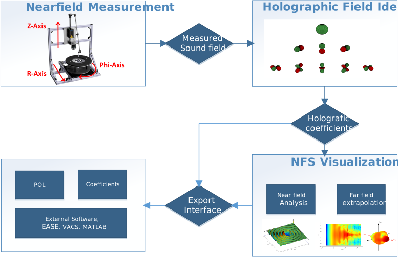
This tutorial will guide you through the process of holographic processing and result visualization of a SCN Near Field Add-On measurement. Most modules used for this process are shared with the NFS System. This tutorial only refers to the particularities of SCN Near Field Add-On measurements. For full reference and further tutorials refer to the NFS Manual.
Processing Object#
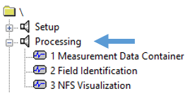
All operations for processing measurement data and analyzing results are located in the Processing Object of the measurement database.
Measurement Data Container#
All data from the automated measurement is saved in the Measurement Data Container. It contains measured impulse responses, their respective coordinates and additional data like microphone sensitivity, frequency resolution and other information. Further metadata for more detailed documentation of the measured DUT can be added via the Property Page of the Measurement Data Container.
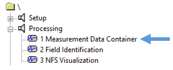
The Measurement Data Container must be Run once for basic processing. Select the Data Container and press the Run Button Ctrl + R.
The Measurement Data Container is a shared module with the NFS System. For further information, refer to the NFS Manual.
Field Identification#
The Field Identification module will perform the parameter fit of the holographic model.
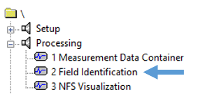
Enter the Property Page of the Field Identification to check the setup.
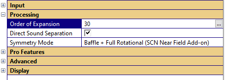
For Field Identifications of SCN Near Field Add-On measurements, the Direct Sound Separation always needs to be enabled and either the Baffle or Baffle + Full Rotational Symmetry mode needs to be selected, depending on the symmetry properties of the measured DUT. (Baffle Symmetry for full scans, Baffle + Full Rotational Symmetry for line scans)
The Order of Expansion provides a target order for the holographic fit. The actual fitting order will be automatically limited to ensure numeric precision and preclude spatial aliasing. In most cases the initial target order of 30 provides good fitting precision. For advanced purposes, custom frequency dependent Order of Expansion targets can be set up.
The full Run of the Field Identification will usually take a few minutes. The result diagrams are periodically updated with new data during the identification process.
The Field Identification is a shared module with the NFS System. For further information regarding result curves and advanced features, refer to the NFS Manual.
NFS Visualization#
The NFS Visualization is used to visualize the measurement results, generate extrapolations into the far field and to generate plots.
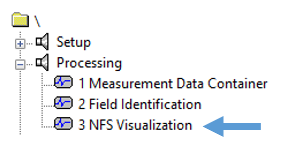
For visualization of SCN Near Field Add-On measurements, the Half-Space Measurement option in the Processing tab of the NFS Visualization always needs to be enabled.
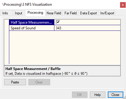
The NFS Visualization is a shared module with the NFS System. For further information, refer to the NFS Manual.
Performing a Measurement#
What is the goal of this tutorial?#
This tutorial will guide you through the execution of a SCN Near Field Add-On measurement. It is expected that the SCN Near Field Add-On is already fully mounted and ready to operate. Refer to the SCN Near Field Add-On Mounting Instruction and follow all instructions if the add-on is not mounted.
Quick Setup Guide#
In addition to this detailed tutorial there is a Quick Setup Guide that summarizes the most important steps of a SCN Near Field Add-On measurement. The guide can be found on the website: Quick Setup Guides.
Start Robotics and Create New Measurement#
Open the KLIPPEL Robotics Software and click the button New Measurement to create a new measurement database.
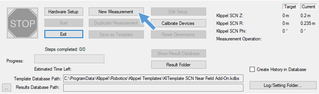
Select the KlTemplate SCN NF - Line Scan.kdbx as a template for the measurement.
This template assumes rotational symmetry of the speaker.
Typical template path is: C:\ProgramData\Klippel\Robotics\Klippel Templates\SCN NF Add-on\.
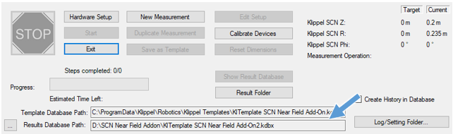
After the template is selected, a path for your measurement database has to be specified. Both template and result database path are displayed at the bottom of the robotics interface after this step.
Note
For a full scan of the speaker, use KlTemplate SCN NF - Full Scan.kdbx template.
Initialize SCN Hardware#
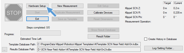
Open the Hardware Setup interface of the Robotics Software by clicking Hardware Setup.
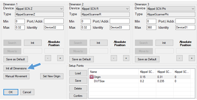
Initialize the axes of the SCN Robotic Hardware by clicking the Init all Dimensions button.
Warning
The SCN hardware will move to initialize its axes after you accept! First the Z-axis will move upwards and calibrate its positive limit. Then the R-axis will move backwards and calibrate on its negative limit, and lastly the Phi-axis will move counter clockwise to its negative limit.
Ensure that no foreign objects or cables are in the moving range! The Near Field Add-on Baffle itself does not obstruct movement and can stay on the SCN if it is already mounted.
Setup and Calibrate Origin Position#
Acoustical measurements with the SCN Near Field Add-On are done in negative R-direction in order to provide maximum distance between the microphone and the SCN portal hardware. Therefore, an origin setup point has to be set close to the positive limit of the R-axis. This origin will be used to map the measurement points to the SCN hardware and defines both DUT position and baffle height to enable a quick setup.
Before the origin is set up, a microphone has to be mounted to the SCN Near Field Add-On Sensor Arm. If the calibration of the microphone to an absolute sound pressure is necessary, this should also be done before continuing with the origin setup, because the microphone position should not be disturbed after the origin setup.
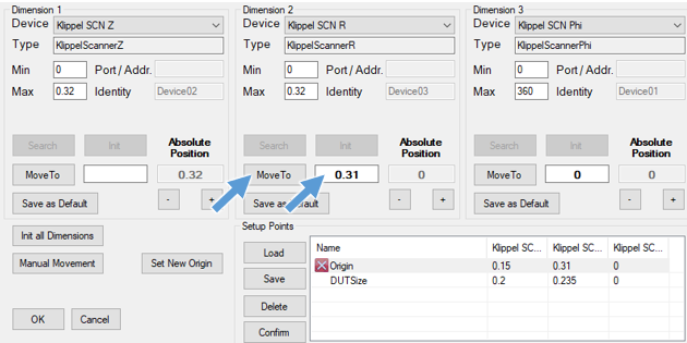
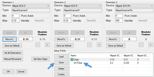
When the microphone is mounted, enter 0.31 as a target position for Dimension 2 (SCN R-axis) and click the MoveTo button. The SCN R-axis will now move to a position close to its positive limit.
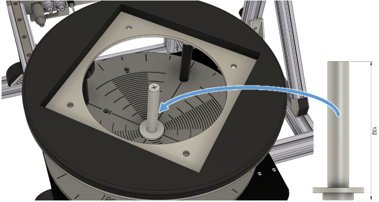
Insert the large SCN Calibration Cone as a calibration target into the center of the turntable.
Now switch the SCN Motor Control to manual mode and use the manual movement controls on the Motor Control to lower the Z-axis until the microphone capsule hovers slightly above the Calibration Cone. (Air gap ≤ 1mm)

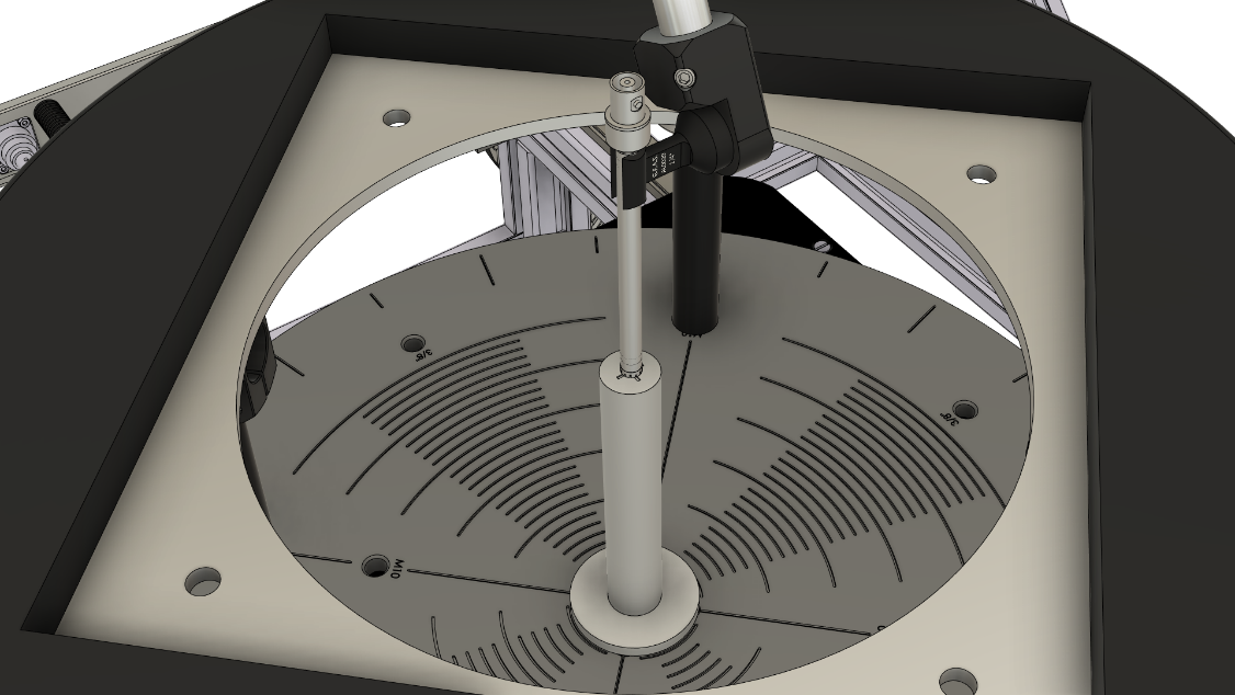
The microphone capsule should be centered in the cross of the Calibration Cone. The lower support arms of the microphone arm feature left- and right-hand threads and can be twisted in order to enable fine adjustment of the microphone position.
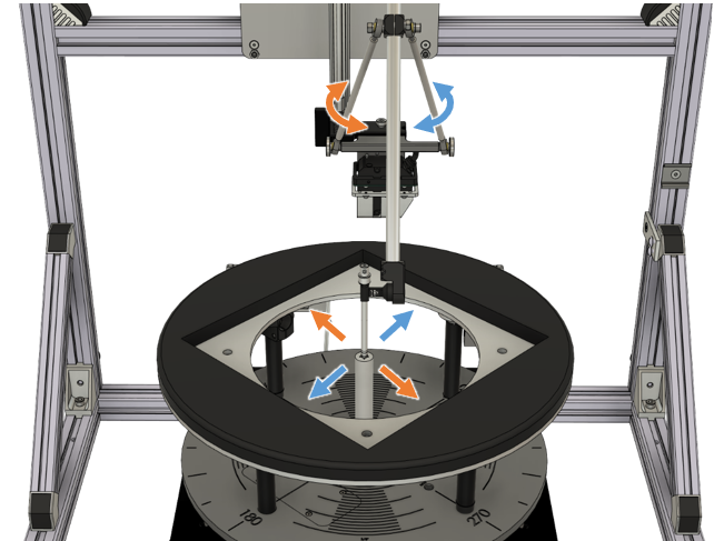
On some SCN units the adjustment range of the lower support arms can be insufficient to reach the Calibration Cone. Refer to the SCN NF Add-On Mounting Instruction for details on how to perform an additional first-time setup.
When the microphone capsule is perfectly centered above the Calibration Cone Cross, save this position in the Robotics Software. First select the Origin setup point, then click the Save button.
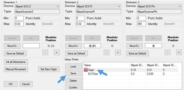
After the Origin is set up, move the microphone back to a safe height of approx. 0.25 either by using the MoveTo command with the Robotics Software or with the manual movement on the Motor Control and remove the Calibration Cone.
Mount DUT#
Transducer DUTs#
Transducers are mounted on the SCN Near Field Add-On Baffle with rectangular wooden Insert Plates. Determine the baffle cutout diameter of your transducer DUT to select an appropriate Insert Plate.
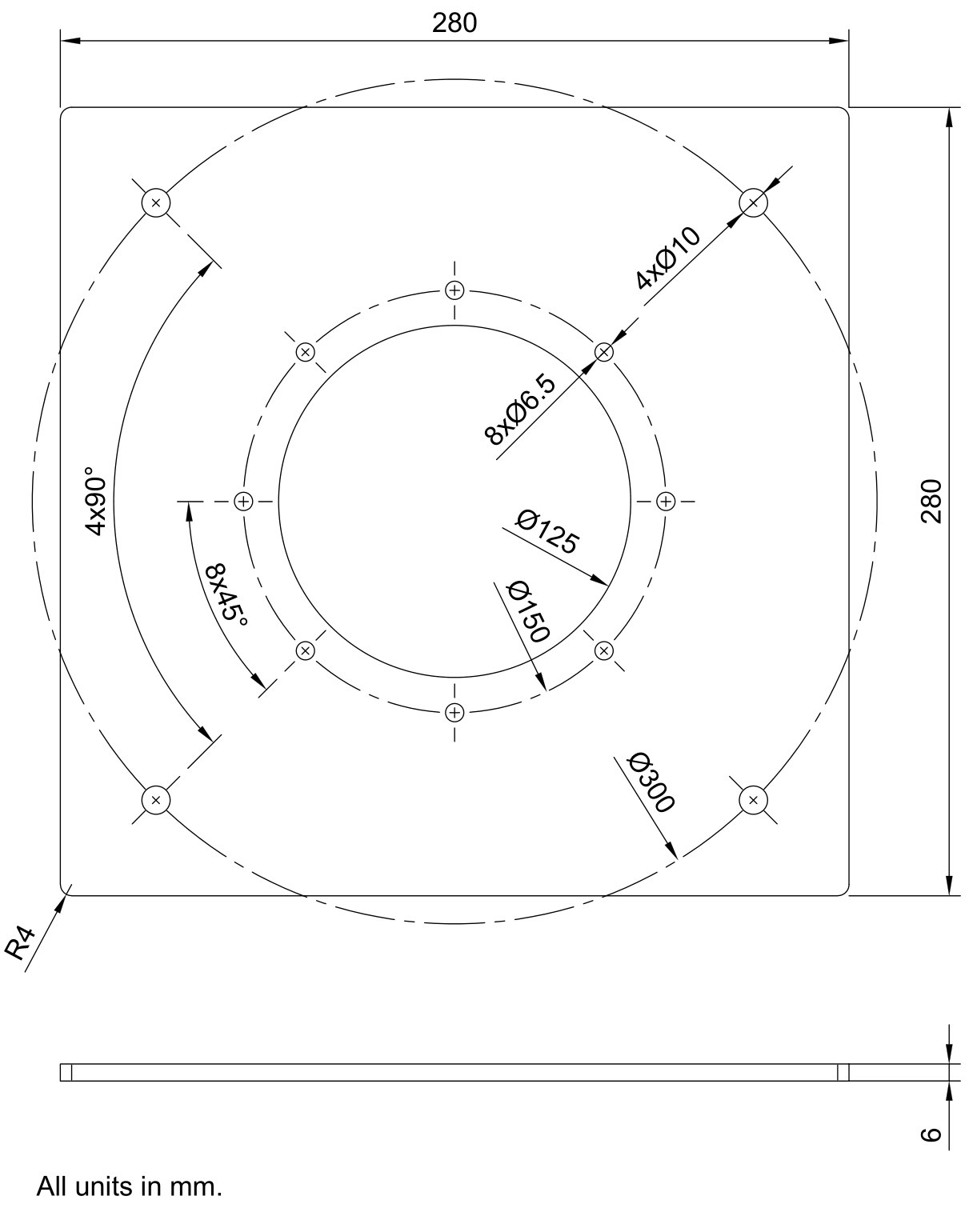
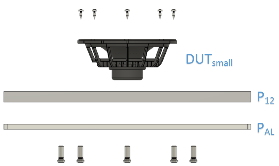
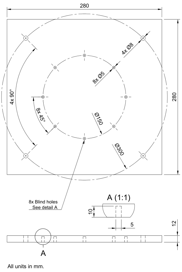
Transducers with cutout diameters up to 125 mm (DUTsmall) are mounted in 12 mm (or 1/2”) thick plates (P12) with an additional Aluminum Reinforcement Plate (PAL). The Reinforcement Plate is screwed to the Insert Plate in close proximity to the DUT.
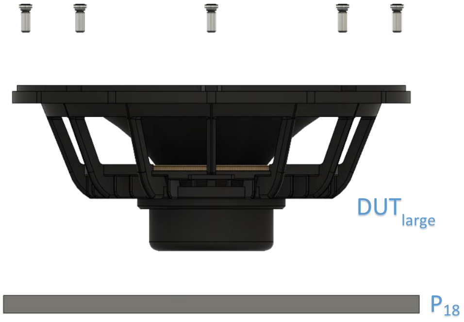
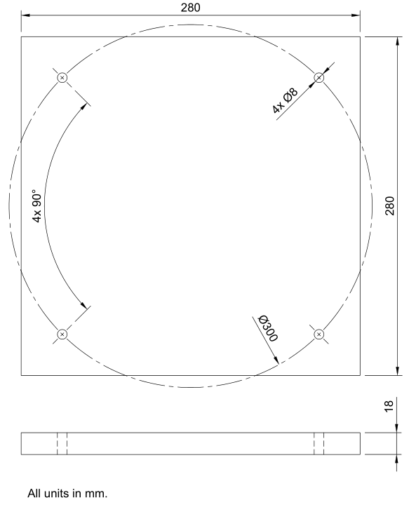
Larger Transducers with cutout diameters up to 250 mm (DUTlarge) are mounted in 18 mm (or 3/4”) thick Insert Plates (P18) without the Reinforcement Plate.
Because baffle cutout and drill patterns are specific for each DUT, the Insert Plates have to be manufactured individually. Refer to chapter Insert Plates for detailed reference and measures of the Insert Plates.
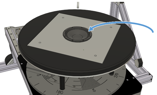
Loosely insert the Insert Plate with the DUT into the SCN Near Field Add-On Baffle. (The Insert Plate is only locked down when measurements in the large signal domain are performed on the SCN Near Field Add-On. Refer to chapter Insert Plates for further details.)
Connect the transducer terminals to the loudspeaker cables in the SCN Turntable and continue with section Configure the Measurement.
In case of active DUTs, the BNC cables of the SCN Turntable can be used to run the connection to the DUT. If additional cables or power lines have to be used, make sure these cables will not obstruct the linear movement and rotation of the SCN Turntable.
Compact Device DUTs#
Compact Devices are placed on a blank Insert Plate in the center of the SCN Near Field Add-On Baffle. The Compact Device is either connected to the loudspeaker cables of the SCN Turntable or to a signal source for active DUTs. The BNC cables of the SCN Turntable can be used to run signal cables without obstructing the movement.
It is recommended to secure the DUT in some manner so that it does not move during the automated scan. The DUT can be fixed, for example, with tape, modelling clay, mounting putty or screws from the bottom.
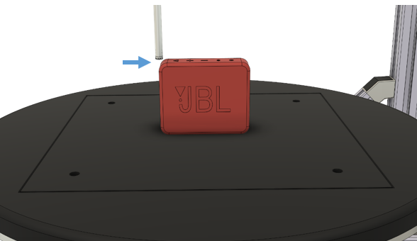
For compact devices the optional Setup Point DUTSize can be set for convenient measurement grid setup. Use the manual movement on the Motor Control to position the microphone at the upper and outer edge of the compact device as shown in the picture und save this position in the Robotics Software. First select the Setup Point DUTSize then click the Save button.
Configure the Measurement#
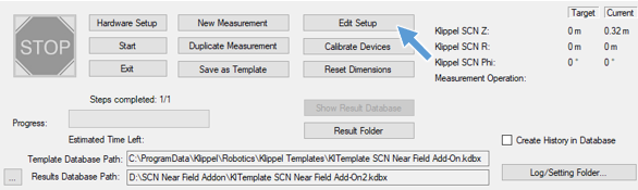
Close the Robotics Hardware Setup window with Ok and return to the Robotics main window. Open the dB-Lab measurement database with the button Edit Setup.
The measurement is configured with the operations in the Setup Object of the measurement database.
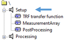
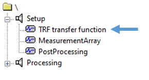
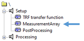
The measurement grid is set up and calculated by the MeasurementArray object. The measurement to acquire the impulse response at each grid point is configured with the TRF transfer function object. The PostProcessing object is used for automated post-processing during the measurement and requires no manual set up.
TRF Setup#
The TRF transfer function object is used to for the automatic measurement of complex transfer functions and impulse responses at the measurement grid positions.
The TRF transfer function is already preconfigured by the SCN Near Field Add-On Template. In most cases only few parameters have to be set up according to the needs of your DUT. Open the Property Page of the TRF. ( or Alt + Enter)
Use the Stimulus page to configure the stimulus used to aquire the transfer function. Set up the Stimulus Voltage, Frequency Range and Length/FFT-Resolution according to the needs of your DUT.
Use the Input page to configure the signal routing according to the connection of your DUT and microphone and to handle microphone calibrations.
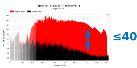
Run the TRF once after the configuration is done to check signal routing, stimulus and signal to noise ratio (SNR). The DUT should reproduce an audible sweep. The SNR can be checked in the result window Y1(f) Input Spectrum or Y2(f) Input Spectrum of the TRF transfer function. A SNR of at least 40 dB in the passband of the DUT is recommended. To increase SNR increase the stimulus voltage or apply averaging.
For further information and reference to the TRF module, refer to the TRF manual.
Measurement and Grid Setup#
Set up the measurement grid by opening the property page of the MeasurementArray operation. ( or Alt + Enter)
Measurement Operation#
TRF transfer function is already preselected as a measurement operation. (Modification is only necessary when custom template databases are created.)
Frequency Resolution#
This parameter defines the frequency resolution for the holographic field identification after the automated measurement. Frequency Resolution is set up according to the needs of the measurement/DUT and is independent of the TRF FFT-Resolution. For most applications a Frequency Resolution between 12 and 24 points per octave is sufficient.
Grid Type#
The Grid Type defines the geometrical base for the measurement grid. Different grid types are used for different sound field symmetries of the DUT. Select a Grid Type that corresponds to the symmetry features of your DUT. If the symmetry is unknown, select Full Scan.
Number of Measurement Points#
The parameter defines the total number of measurement points in the grid. This number also determines the maximum order of spherical harmonics which can be used in the holographic field identification. For DUTs with high directivity or complex directivity patterns, higher orders and more measurement points are needed. Symmetry assumptions on the other hand can drastically reduce the needed number of points. Refer to the following table as a guide for typically needed measurement points.
Measurement Points per DUT#
- Round Transducers
- Symmetry: RotationalGrid Type: Line ScanRecommended Point Count: 30Approximate Measurement Time: 5 min
- Transducers (sound power)
- Grid Type: Full ScanRecommended Point Count: 150Approximate Measurement Time: 30 min
- Transducers (full directivity)
- Grid Type: Full ScanRecommended Point Count: 300-500Approximate Measurement Time: 1h
- Transducer Arrays
- Grid Type: Full ScanRecommended Point Count: 500-800Approximate Measurement Time: 2h
- Compact Device (sound power)
- Grid Type: Full ScanRecommended Point Count: 150Approximate Measurement Time: 30 min
- Compact Device (full directivity)
- Grid Type: Full ScanRecommended Point Count: 500Approximate Measurement Time: 1h
DUT Type#
This parameter defines the DUT Type, which has an impact on the measurement grid generation.
Transducer Type DUTs are only slightly protruding into the front half space of the baffle. Therefore, a simple collision avoidance technique is used for these DUTs. Measurement points beneath a configurable Safety Distance are not measured and will later be interpolated in the holographic field identification.
Compact Device Type DUTs occupy a relevant space inside the front half-space of the baffle. Therefore, a more complex collision avoidance technique is used for these DUTs. The DUT Height parameter has to be defined separately and the movements of the SCN are planned accordingly to avoid collisions.
Note
The Compact Device DUT Type can also be used for Transducer Type DUTs that are protruding very far out of the baffle.
DUT Diameter#
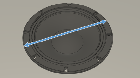
The DUT Diameter parameter is used to calculate the radius of the measurement grid. Measure and enter the size of the DUT. A safety margin and radius offset for the microphone capsule size is added automatically.
When the optional DUTSize Setup Point has been set in the Robotics Hardware Setup, the DUT Diameter is automatically calculated.
DUT Height#
The DUT Height parameter is only available when a Compact Device DUT Type is selected. The DUT Height is used for advanced collision avoidance between the microphone and larger DUTs. Measure and enter the height of the DUT.
When the optional DUTSize Setup Point has been set in the Robotics Hardware Setup, the DUT Height is automatically calculated.
Safety Distance to Baffle#
The Safety Distance to the baffle defines a height beneath which points are not measured in order to avoid collision between the microphone and the baffle or slightly protruding DUTs. Measure and enter the height of Transducer Type DUTs, cables for active DUTs or any other obstructions on top of the baffle.
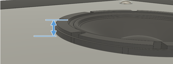
A minimum Safety Distance of 5 mm is recommended even if the DUT does not protrude out of the baffle.
Calculate and check grid#
After all parameters of the MeasurementArray are set up, close the Property Page and Run the MeasurementArray object by pressing the Run Button (Ctrl + R). Double click the MeasurementArray to display and check the grid.
When everything is okay, close the dB-Lab Database and return to the Robotics Software.
Start the Measurement#
Start the automated measurement by clicking the Start button in the Robotics Software.
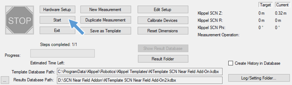
After the measurement is started, the SCN will move and perform the measurements at all points. The green progress bar will advance, and an estimated remaining time will be available after a few measurement points. The measurement can be stopped or paused with the red “Stop” button in the Robotics Software.
In case of emergency, the measurement can also be stopped with the red Emergency Stop Button on the SCN Z-Axis or Motor Control. After an Emergency Stop, the measurement cannot be resumed and will have to be restarted completely.
Analyze Measurement Data#
The measurement is finished when the green progress bar in the Robotics Software is fully advanced and the Stop button has turned grey again. The result database can now be opened with the Show Result Database button.
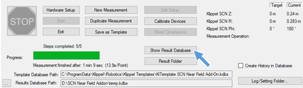
Refer to the chapter Viewing Results for more information on how to process and view the measurement results.
Asynchronous and Open Loop Testing#
What is the goal of this tutorial?#
For audio devices that do not have an analog input the measurement stimulus needs to be transmitted via a wireless connection or is played by the device under test itself.
This tutorial shows the measurement of a Bluetooth® loudspeaker using the SCN Near Field Add-On. Other wireless devices (e.g. Wifi) can be measured similar.
Only the particularities of such a Bluetooth® loudspeaker measurement are discussed. It is required to be familiar with the general workflow of measurements with the SCN Near Field Add-On discussed in chapter Performing a Measurement.
Additional hardware required#
Bluetooth® Transmitter#
3rd party Bluetooth® transmitter with an analog input (e.g. 3.5 mm jack) or digital input (e.g. SPDIF). It can be either a professional transmitter or a common consumer product.
Note
When selecting the transmitter, make sure it matches the codex of the device under test (e.g. high quality or low latency).
2nd Microphone#
2 microphones are required to perform an asynchronous measurement.
Microphone 1: Test microphone
Microphone 2: Synchronization microphone
The 2nd microphone is used for synchronization of the result data of all measurement points in order to provide correct phase information for the Field Identification.
The 2nd microphone is also used for reliability monitoring and the detection of disturbed measurement points, due to dropouts in the wireless connection or unexpected events like empty DUT batteries. These disturbed measurement points are automatically repeated.
Robotics Setup#
Most steps of the Robotic Software and the measurement setup of an asynchronous measurement are identical to a normal measurement.
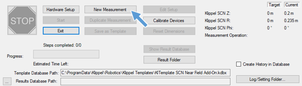
When creating a New Measurement select the KlTemplate SCN NF - Bluetooth.kdbx as a template
for the measurement. Typical template path is: C:\ProgramData\Klippel\Robotics\Klippel
Templates\SCN NF Add-on\.
Proceed with initialization and origin setup in the same manner as with a normal Near Field Add-On measurement.
Measurement Setup#
Positioning the DUT#
The DUT must be placed in the center of the round baffle on a blank Insert Plate.
In most setup scenarios the main radiation axis of the DUT will not point upwards, in a normal direction to the baffle. The direction and height of the main radiation axis must be noted during the measurement setup and is later needed for defining a loudspeaker coordinate system in order to analyze directivity.
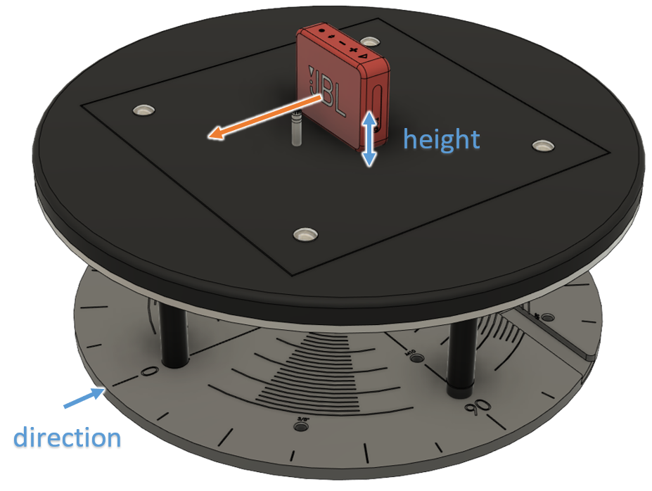
The direction of main radiation axis can be read on the turntable of the SCN. The height should be measured and in most cases is half the height of the DUT. In the example above the direction of the main radiation axis (orange) points towards 0° and has a height of 30 mm.
These values are later needed to set the global reference coordinate system in the NFS Visualization.
Positioning and mounting the 2nd microphone#
The synchronization microphone must be mounted in close proximity to the DUT to get a high signal to noise ration and robust measurement conditions.
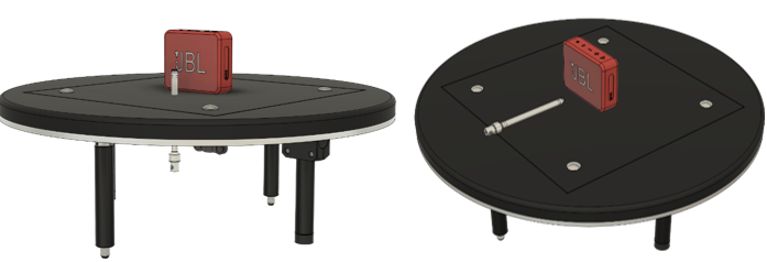
The 2nd microphone can either be mounted through the baffle by drilling an additional hole (left drawing) or mounted in a flat configuration and the baffle (right drawing).
In both cases the microphone must be sufficiently fixed so that it does not move during the automated measurement. Removable mounting putty or adhesive tape can be used for this purpose.
Connection of DUT and microphone#
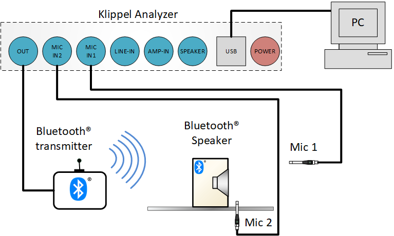
The 2nd synchronization microphone should be connected with the BNC cables inside the SCN Turntable so that the SCN movement stays unobstructed.
Note
For asynchronous measurements the main measurement microphone needs to be connected to Input 1 of the analyzer hardware. Note that this differs from normal measurements with the SCN Near Field Add-On!
Bluetooth pairing and TRF test#
After the measurement setup the DUT has to be paired to the used Bluetooth transmitter. For the MegaSig U980 Bluetooth interface recommended by Klippel the IO Input Output module with IO Bluetooth template can be used. For other 3rd party interfaces refer to the manufacturer’s instructions.
When the DUT is paired the TRF transfer function should be run in order to check correct connection, pairing and excitation level for sufficient SNR. Check both the Y1(f) and Y2(f) Input Spectrum for a SNR of 40 dB or higher in the passband of the DUT.
After Bluetooth pairing and TRF check the measurement grid is generated as usual and the automated measurement can be started in the Robotics Software.
Measurement grid and automated measurement#
The measurement grid is generated with the MeasurementArray module in the same manner as with normal measurements.
The Asynchronous Measurement section of the MeasurementArray is preconfigured in the template to work with most wireless DUTs. Only for very directive DUTs adjustments can be necessary. Refer to section MeasurementArray in this case.
After Bluetooth pairing, TRF test and measurement grid generation is done dB-Lab can be closed and the automated measurement is run as usual in the Robotics Software.
Additional steps after measurement#
After the automated measurement with the Robotics Software is finished open the result database in dB-Lab.
Checking for disturbed points#
For asynchronous measurements the MeasurementArray, used to generate the measurement grid in the beginning, must be run again after the measurement to check for disturbed points.
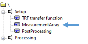
The windows of the MeasurementArray will now show which measurement points where directly completed or completed after repetition and which points could not be completed and are disturbed. The MeasurementArray will also provide a warning if there are disturbed points present.
Depending on the directivity of the DUT it is possible that a few measurements points are systematically disturbed. In most cases this happens due to reflections on the SCN portal hardware. If only up to 3 % of the measurement points where disturbed the measurement is still fine as a whole.
When a large number of points is disturbed, first the wireless connection should be checked and DUT power supply should be checked.
If there are still a lot of disturbed points present despite solid wireless connection a new measurement with different orientation of the DUT or manual selection of a narrower passband in the MeasurementArray can be a remedy.
Handling of Data Container and Field Identification#
The handling of the Data Container and Field Identification for asynchronous measurements is the same as with normal measurements with the SCN Near Field Add-On.
Visualization#
In the Input section of the NFS Visualization the Global Reference System has to be enabled in order to visualize the NFS data in the correct loudspeaker coordinate system.
The height and direction of the main radiation axis noted during the measurement setup is used here.
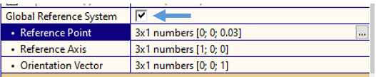
The Reference Point describes the acoustic center of the speaker and is [0; 0; height].
The Reference Axis describes a directional vector from the Reference Point in the direction of the main radiation axis. When this axis is directed towards 0° of the SCN Turntable the Reference Axis is [1; 0; 0]. For other directions the Reference Axis is:
SCN turntable direction |
Reference Axis |
|---|---|
0° |
[1; 0; 0] |
90° |
[0; 1; 0] |
90° |
[0; 1; 0] |
180° |
[-1; 0; 0] |
270° |
[0; -1; 0] |
The Orientation Vector describes a directional vector from the Reference Point in the direction of \(\phi = 0°\) of the DUT. For Measurements with the SCN Near Field Add-On this is typically [0; 0; 1] pointing upwards in accordance to the IEC standard 60268-21 coordinate system.
SCN NF - Reference#
Coordinate System#
The holographic measurement approach is based on spherical basic functions. Therefore, the measurement grid generation and measurement evaluations are done in spherical coordinates. A reference coordinate system based on the IEC standard 60268-21 is used. According to the standard, the reference system is defined by the reference point \(r_{\text{ref}}\), the reference axis \(n_{\text{ref}}\) and the orientation vector \(o_{\text{ref}}\).
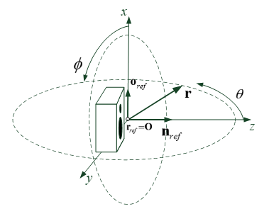
The robotic hardware of the SCN unit forms a cylindrical coordinate system. A coordinate transformation to and back from the SCN hardware coordinate system is done automatically based on the Setup Points set in the Robotics Hardware Setup.
Measurement Process#
The measurement process with the SCN Near Field Add-On is automated by the KLIPPEL Robotics Software. The measurement data is processed and visualized with the Klippel dB-Lab suite. The KLIPPEL Scanner Software for laser-based vibration scans is not involved in the SCN Near Field Add-On measurement process.
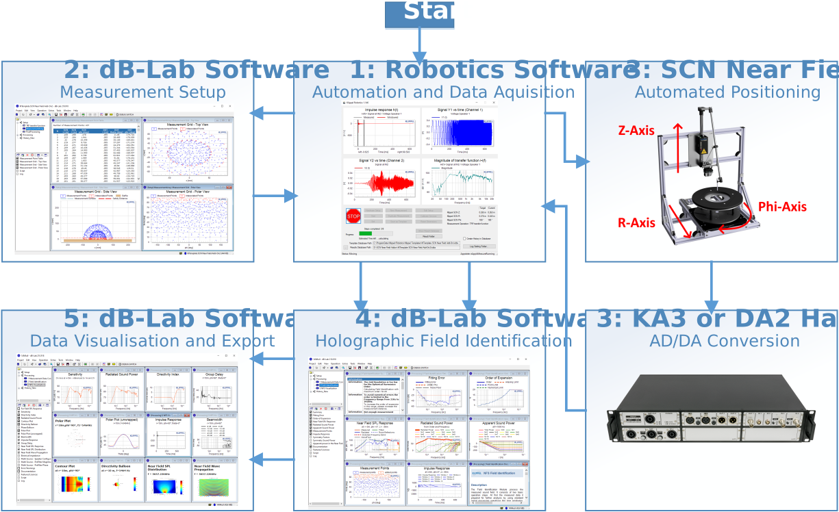
The main steps of a SCN Near Field Add-On measurement are:
1a: Start Robotics Software
1b: Select SCN Near Field Add-On Template
1c: Initialize SCN axes
1d: Setup origin
1c: Mount and connect DUT
2: Setup measurement and generate measurement grid in dB-Lab
3: Automated measurement
4: Signal processing and holographic field identification in dB-Lab
5: Visualization of measurement results in dB-Lab
For more detailed step by step instructions with practical measurement examples, refer to the tutorials Viewing Results and Performing a Measurement.
Parameters#
MeasurementArray#
Measurement Setup#
- Measurement Operation
Defines the measurement operation, which will be automatically performed (usually TRF – Transfer Function Measurement).
- Frequency Resolution
Defines the frequency resolution for the holographic field identification after the automated measurement. It is limited in a range from 6 to 48 points per octave.
Grid Configuration#
- Grid Type
Defines the geometrical grid type for the measurement points. Different grid types are used for different sound field symmetries of the DUT.
- Number of Measurement Points
Defines the total number of measurement points in the grid. This number also determines the maximum order of spherical harmonics which can be used in the holographic field identification.
- DUT Type
This parameter defines the DUT Type, which has an impact on the measurement grid generation in order to avoid collisions.
- DUT Diameter
The DUT Diameter parameter is used to calculate the grid radius of the measurement grid. Directly enter the size of the DUT.
- DUT Height
The DUT Height parameter is only available when a Compact Device DUT Type is selected. The DUT Height is used to avoid collisions between the microphone and DUTs which occupy space in the front half-space of the baffle.
- Safety Distance to Baffle
The Safety Distance to the baffle defines a height beneath which points are not measured in order to avoid collision between the microphone and the baffle or slightly protruding DUTs. A minimum Safety Distance of 5 mm is recommended.
Setup Points#
- Origin
The Origin is a required setup point in the Robotics Hardware Setup. It is set by positioning the microphone directly above the large SCN Calibration Cone and saving the Origin Setup Point.
- DUTSize
The DUTSize is an optional setup point in the Robotics Hardware Setup which can be used for easy setup up DUTs with odd shapes. It is set by positioning the microphone at the outermost top edge of the DUT and saving the DUTSize Setup Point.
Asynchronous Measurement#
- Synchronization
When activated the asynchronous measurement for wireless or open loop testing is performed. In this mode all measurements are synchronized with a second microphone. DUT and wireless connection are also monitored for correct behavior with the additional microphone.
- Number of Initial measurements
Defines the number of initial measurements which are performed and averaged to provide a baseline for the reliability check of the asynchronous measurement.
- Maximum Number of repetitions
Defines how often a disturbed measurement point will be repeated. When deactivated disturbed points will be repeated indefinitely until no disturbed points are left.
- Frequency Range (Passband)
Defines the frequency range in which the device is checked for reliable and correct behavior. When deactivated the passband is automatically determined. When activated a custom frequency range can be defined.
Insert Plates#
DUTs are mounted in the SCN Near Field Add-On with easy-to-manufacture and cost-effective wooden insert plates. With each SCN Near Field Add-On, a basic set of insert plates is supplied to enable quick setup and first operation. Additional plates have to be manufactured individually for each DUT. It is recommended to use plywood or a polymer plastic for the inserts rather than fiberboard in order to keep baffle vibrations to a minimum.
Mounting Insert Plates in the Baffle#
Small Signal Measurements#
For holographic measurements with the SCN Near Field Add-On and other measurements in the small signal domain (for example a KLIPPEL LPM – Linear Parameter Measurement on the SCN Near Field Add-On), the Insert Plates are loosely inserted into the baffle. This splits the baffle into separate substructures and minimizes baffle vibrations.
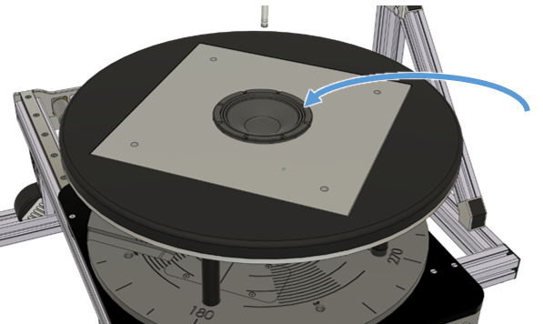
Large Signal Measurements#
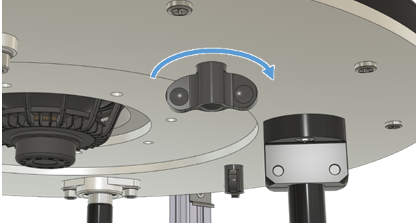
For measurements on the SCN Near Field Add-On in the large signal domain like the KLIPPEL LSI3 – Large Signal Identification or distortion measurements which require high transducer excursion, the Insert Plates are locked to the baffle with screws.
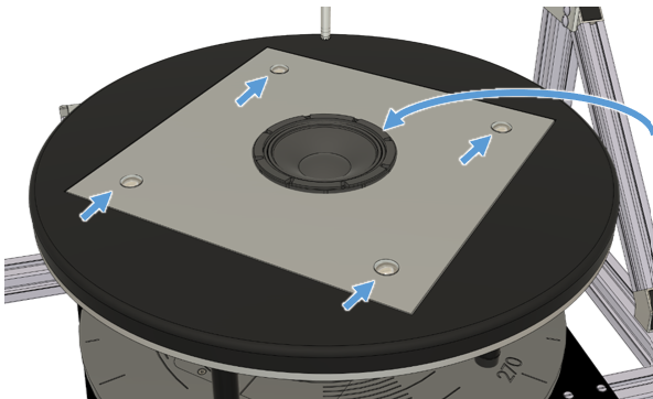
The four M6 half round screws supplied with the SCN Near Field Add-On will automatically fit in the Insert Plate and are locked down with wing nuts from the bottom of the baffle. No tools are required.
Insert Plate Dimensions for small DUTs#
Insert Plate Dimensions for large DUTs#
Aluminum Reinforcement Plate for small DUTs#