
Poly2SCN – Interface#
Poly2SCN - Tutorial#
Overview#
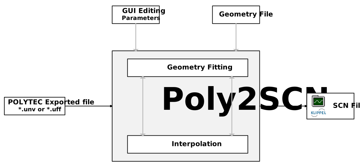
The Poly2SCN module converts arbitrary spaced measurement grids measured with a Polytec Laser Doppler Vibrometer into a Klippel SCN data format compatible with the Klippel Scanner software and other modules. This module can handle measurement data exported to a Universal File Format (UFF) containing geometry and transfer function vibration data. After defining the resolution of the target grid, the imported data is interpolated onto the synthesized grid and exported to an SCN data container and SCN file.
What is the goal of this tutorial?#
This tutorial makes you familiar with the Poly2SCN module.
The main part will explain the workflow and different modes of the conversion process. A step-by-step approach will explain and guide through the graphical user interface of the Poly2SCN module.
Using Poly2SCN#
Starting Poly2SCN#
Choose or create a new Object  and assign a new Poly2SCN operation
  to it.
Click on Run
to it.
Click on Run  to open the graphical user interface, which we will refer to as “the GUI” in
the following:
to open the graphical user interface, which we will refer to as “the GUI” in
the following:
Note
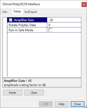
To define the Amplification Gain of the used amplifier, open the properties  of the Poly2SCN operation.
Amplifier Gain#
The exported Polytec data usually contains the measured transfer function in the form of vibration/voltage. The reference voltage is typically the output voltage of the Polytec Hardware and not the amplified voltage measured at the DUT terminals. To compensate for the amplification gain inside Poly2SCN, open the properties of the Poly2SCN operation, go to tab Setup, activate the checkbox Amplifier Gain, and enter the gain of the used amplifier in dB.
Note
The Amplifier Gain can be measured for example with a TRF operation. The gain of the power amplifier is display in the “Table Results + Settings” window in the section “Further Results”.
Rotate Polytec Data#
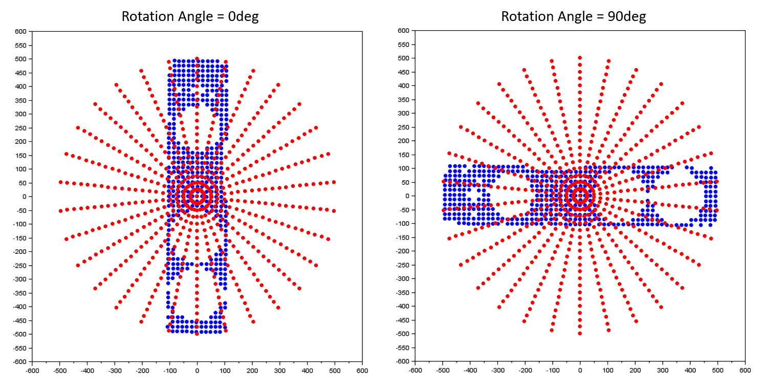
The exported Polytec data is usally orientated according to standard coordinate system, where x is representing the horizontal and y is representing the vertical axis. It is highly recommended to verify the correct orientation of the EUT. Open Klippel SCN, select tab Radiation Analysis and check the correct orientation of the EUT in accordance with the IEC standardized coordinate systems. However, if the orientation mismatches the IEC standardized coordinate systems it is possible to change the orientation of the EUT inside Poly2SCN.
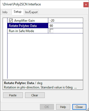
Open the properties of the Poly2SCN operation, go to tab Setup, and Rotate Polytec Data, and enter the angle in deg to rotate the data in phi-direction.
Note
There is no possibility to change the orientation of the EUT in KLIPPEL SCN.
Load Polytec File#
To open the file selection dialogue, click the button “Load Polytec File”. Select a UFF-File (file formats *.uff or *.unv) exported from a Polytec measurement containing a set of vibration/voltage transfer functions. The vibration data in this transfer function may be displacement, velocity or acceleration.
Note
Importing large files increases the computation time during import and conversion. To speed up the process make sure to export only one valid set of transfer functions and not to export additional unnecessary data.
Since a small number of users have encountered problems with loading UFF-files via the GUI, it is also possible to specify a uff-file in the input property page of the operation in dB-Lab. To do so, activate the checkbox Run in Safe Mode. If a valid file name is specified under Polytec File Path, then the button Load Polytec File in the GUI will trigger loading this file. In this case, if you want to change the file to be loaded, exit the Polytec GUI, change the file in the input property page and run the Poly2SCN operation again.
Vibration/Geometry Selection#
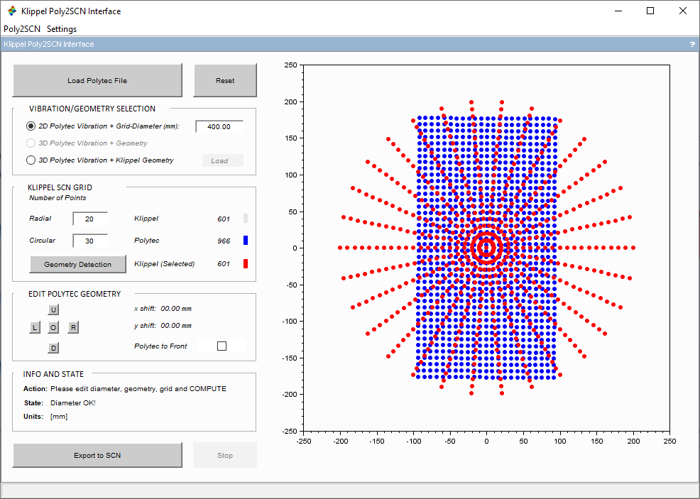
For this example, a UFF-File without 3D geometry data is imported. This enables the modes 2D Polytec Vibratio and 3D Polytec Vibration + Klippel Geometry. Since no 3D geometry data is provided by the imported file, the mode 3D Polytec + Vibration is unavailable.
Using 2D Polytec data + Grid-Diameter
By clicking on the first option, the 2D Polytec Vibration mode is selected and the parameter Grid-Diameter becomes editable.
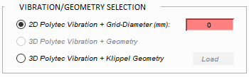
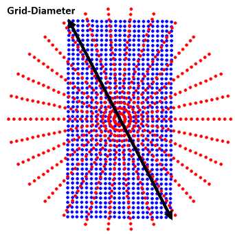
Enter the maximum diameter of the area measured by the Polytec system. After a valid diameter is entered, the imported geometry is scaled to the specified value and visualized in the graphical representation section.
Note
The grid diameter is not the same as the diameter of the cone or cone-surround assembly. If the surround or cone is not measured to the edge, the grid diameter is smaller than the cone or cone-surround diameter. Make sure to determine the grid diameter accurately.
Using 2D Polytec data with 3D Klippel geometry data
If a Klippel geometry scan of the measured transducer is available, the option 3D Polytec Vibration + Klippel Geometry can be chosen. After selecting this option, the Load button becomes available additionally to the Grid-Diameter. After loading the Klippel geometry scan, a 3D geometry of the transducer is available to interpolate the measured Polytec grid on the imported 3D geometry.
Note
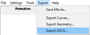
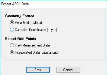
The measured 3D geometry has to be exported from the Klippel SCN software. To do so, click on Export to open a drop-down menu and select Export ASCI. An export dialog will open. Select Polar Grid (r, phi, z) and Interpolate Data (original grid). Click on Start to complete the export process.
Using 3D Polytec data
If the loaded UFF-file contains 3D geometry data, the option 3D Polytec Vibration + Geometry will become available as well. When choosing this option, the Grid-Diameter does not have to be entered. It is calculated from the geometry data of the imported UFF-file.
Note
The geometry data of some points measured by the Polytec system may be corrupted by noise or other disruptive factors. Please check that the measured data of the Polytec measurement is well enough. Due to the interpolation process noisy or corrupted points will have an impact on neighboring points in the Klippel grid.
Klippel SCN Grid#
The next step is to edit the target grid which will be exported by the Poly2SCN module. The radial and circular resolution of the Klippel SCN Grid (red points) can be adjusted here.
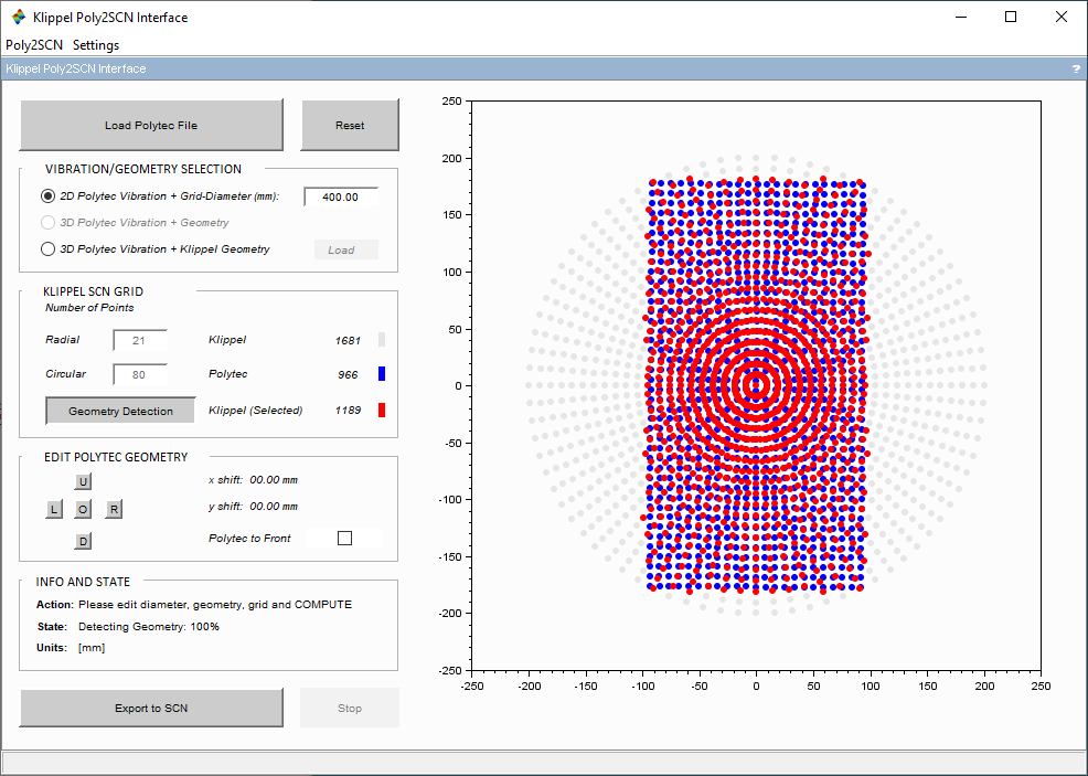
For rectangular-shaped, oval-shaped or irregularly-shaped geometries, the button Geometry Detection needs to be pressed. This option disables the points of the Klippel SCN Grid which are outside of the measured area. The disabled points are visualized in grey and will be assumed as rigid. The active (selected) points are visualized in red and used for the mapping process. The number of all Klippel, Polytec and selected Klippel points is displayed. This step is necessary to avoid a wrong extrapolation of the measured vibration in the area outside of the measured area.
Note
Asymmetrically or irregularly shaped geometries that cannot be represented by a circle can be detected by the Geometry Detection. Without using the Geometry Detection, the conversion process will extrapolate the vibration data at points outside of the measured area and produce wrong results.
Edit Polytec Geometry#
For further post processing with the Klippel software (e.g. RMA – Rocking Mode Analysis) the measured transducer needs to be centered on the circular Klippel SCN Grid.
The position Polytec grid (blue) may have to be adjusted relative to the of the Klippel SCN Grid. The action of the controls will be reflected immediately in the plot window (section 7). The current x- and y-offset is displayed as well. The controls are:
Shift [L/R/U/D]: Displacing the geometry up, down, left and right as indicated by the buttons.
Origin [O]: Returns all the edit geometry parameters to their initial states.
Polytec to Front: Displays the Polytec Grid in the foreground
As soon as the grid points are sufficiently centered, the conversion process can be continued by pressing the button Export to SCN.
Export to SCN#
By clicking on Export to SCN the conversion process is started with the current settings. The transfer function data is read from the loaded UFF-file and geometrically interpolated to calculate the vibration data points of the Klippel SCN Grid. The resulting data is exported into a SCN data container operation underneath the Poly2SCN operation in the database. The *.ksp Klippel Scanner Project file, the *.sce and *.bin files to be opened with the Klippel SCN software are also written to the hard drive in the same directory where the Polytec file is located. A new folder, containing the files with the name of the database is created.
Viewing Results#
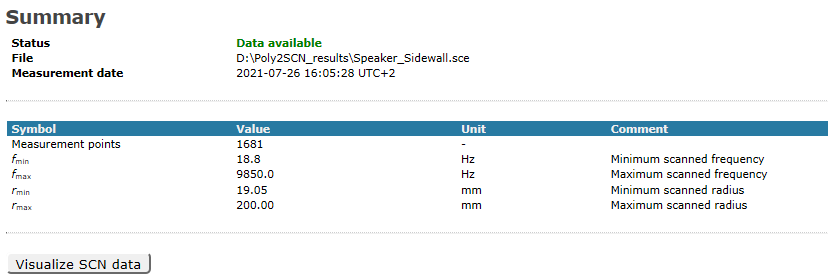
To view the results of the Poly2SCN module the Klippel SCN – Scanning Vibrometer software is needed. This can be done by either opening the Klippel Scanner Project file on the hard drive or opening the created SCN data container operation in dB-Lab. The results can be opened by clicking on the Visualize SCN data button of the Summary window of the operation.
For further information about the Klippel SCN software please refer to the SCN – Scanning Vibrometer manual.
Poly2SCN – Reference#
Overview#
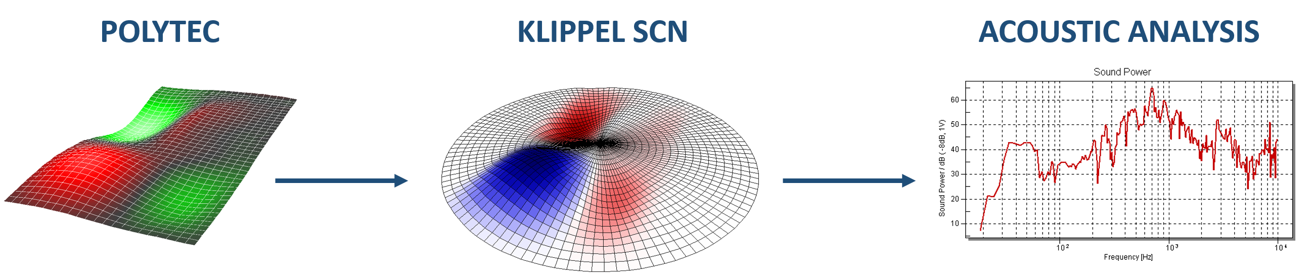
The Poly2SCN module allows users of the Polytec Laser Doppler Vibrometry to utilize the modules of the Klippel Scanner Landscape. By converting the measurement data of a Polytec measurement into the Klippel SCN format the user gains access to the visualization and post processing of the Scanner software. Additionally, the post processing module RMA – Rocking Mode Analysis may be used to perform further analysis on the distributed vibration data and help to improve the design and development of electroacoustic transducers.
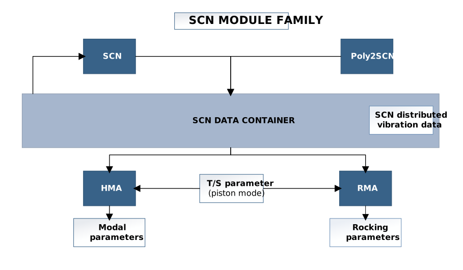
Vibration data measured with Polytec Scanning Vibrometers can be imported fast and easily into the Klippel SCN – Scanning Vibrometer software using the Poly2SCN Interface. Arbitrary measurement grids generated in the Polytec scanning process can be edited and interpolated over an optimized grid for a suitable post processing in the Klippel SCN software.
The output Klippel Scanner file *.ksp containing the vibration data measured with a Polytec system and mapped over a desired geometry, can be generated by the following two simple steps:
Loading an exported Polytec *.uff/*.unv file and selecting the desired geometry option,
Setting the geometry parameters to get the best match between the Polytec points and the synthesized grid.
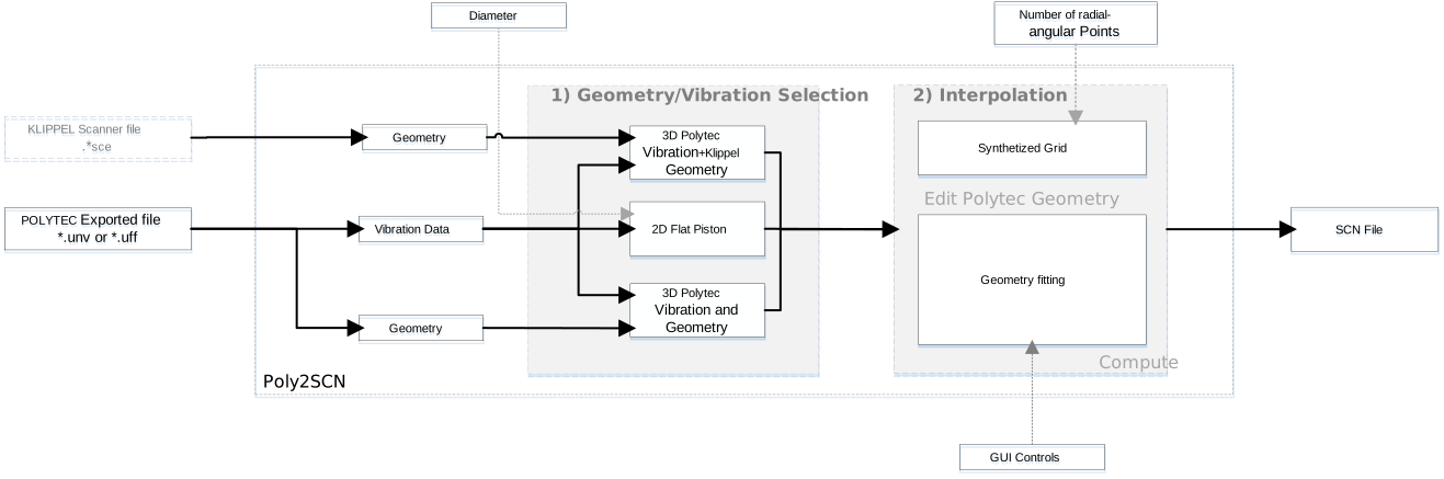
Poly2SCN supports exported Polytec files containing 2D or 3D geometry data. By loading this file, the interface will automatically enable the Geometry/Vibration Selection options compatible with the measured file and the user can choose the more convenient way for his study.
Graphical User Interface#
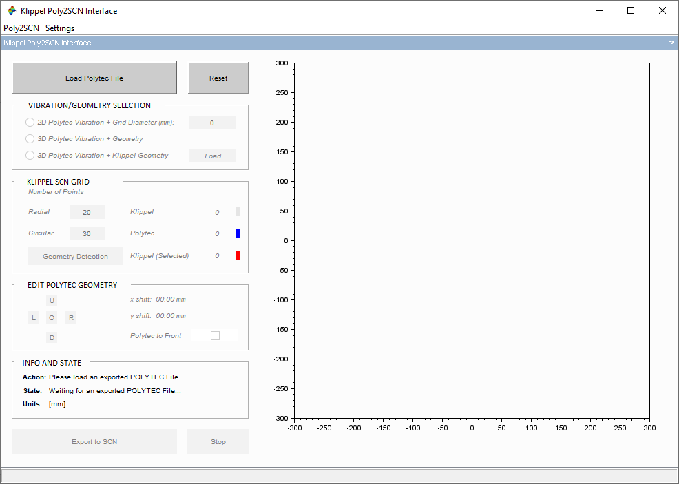
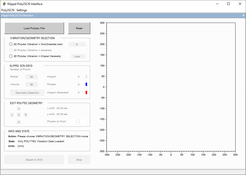
The Poly2SCN GUI is arranged in seven sections to provide an intuitive and sequential workflow through the data import process. The first six sections (1-6) allow the user to interact with the interface, loading files, modifying geometry parameters, provide information about the state of the process and computing while section (7) visualizes the Polytec and the Klippel grid. Each section is described hereafter:
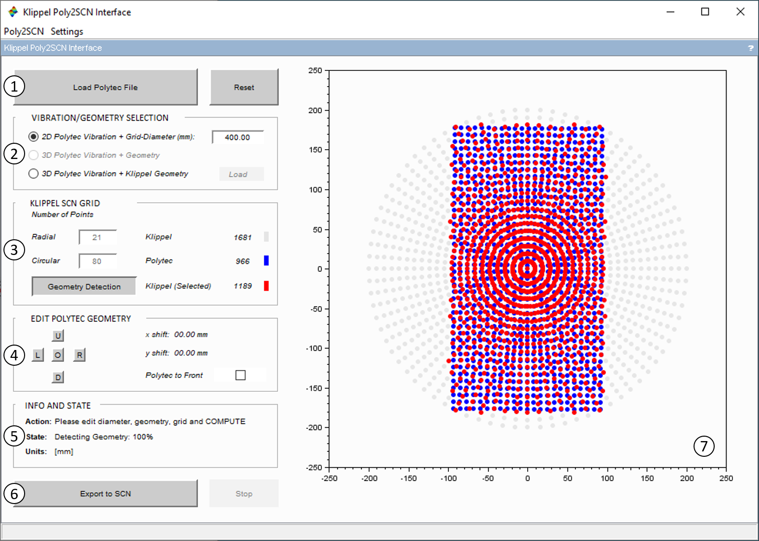
Load Polytec File and Reset#
Load Polytec File: Shows a file selection dialog to choose an UFF-file. (*.unv or *.uff).
Reset: Resets the state of the Poly2SCN module to the initial state.
Note
If you encounter problems loading, please check the “safe mode” option in the input property page of the Poly2SCN operation.
Vibration Geometry Selection#
In this section the interpolation mode of the loaded Polytec data is selected. Depending on the imported UFF-file various options are available here.
There are three different modes:
2D Flat Piston: This mode projects the vibration data over a flat synthesized grid. This mode is useful if no geometry information is available for the driver. In the case of a Polytec file containing only 2D geometry data, the maximum diameter of the measured grid is required.
3D Polytec Vibration + Geometry: This mode is available when 3D geometry data is provided in the exported file. It will map the vibration and geometry points onto an optimized synthesized grid.
3D Polytec Vibration + Klippel Geometry: This mode can be used with any kind of Polytec data and projects the vibration points onto a geometry measured with the displacement sensor of the Klippel SCN software.
Note
The 3D Polytec Vibration + Klippel Geometry mode requires a Klippel file containing the geometry data. The maximum grid diameter needs to be specified as well to map the measured grid onto the geometry data.
Grid-Diameter: This value needs to be specified for the modes 2D Flat Piston and 3D Polytec Vibration + Klippel Geometry. It is used to scale the coordinates of the measurement points of the Polytec grid to absolute values. This is necessary if the imported file does not contain valid 3D geometry data, because in this case the coordinates of the measurement points will not have the correct absolute value. In case the imported file contains valid 3D geometry data, the correct value will be estimated automatically.
Load: This button opens a file selection dialog to select the Klippel geometry data that is used for the mode 3D Polytec Vibration + Klippel Geometry.
Klippel SCN Grid#
In this section, the parameters for the target Klippel SCN Grid are specified. The radial and circular resolution of the Klippel SCN Grid (red points) can be adjusted here.
Radial: Specifies the radial resolution of the target grid
Circular: Specifies the angular resolution of the target grid
Geometry Detection: By pressing this button, the target grid is truncated to match the geometry of the Polytec grid. All points beyond the measured grid are disabled and assumed as rigid.
Edit Polytec Geometry#
For further post-processing with the Klippel software (e.g. RMA – Rocking Mode Analysis) the measured transducer needs to be centered on the circular Klippel SCN Grid.
The position of the Polytec grid (blue points) may have to be adjusted relative to the synthesized Klippel SCN Grid. The action of the controls will be reflected immediately in the plot window (section 7). The current x- and y-offset is displayed as well. The controls are:
Shift [L/R/U/D]: Displacing the geometry up, down, left and right as indicated by the buttons.
Origin [O]: Returns all the edit geometry parameters to their initial states.
Polytec to Front: Displays the Polytec Grid in the foreground
Info and State#
In this section messages regarding the actions that should be taken by the user (Action) as well as information about the state of the Interface (State) will be displayed.
Export to SCN#
Export to SCN: : A click on the Export to SCN button starts the data loading, the frequency interpolation and the spatial interpolation process. This button should be pushed when the best fitting has been reached with the geometry. This action generates the *.ksp (Klippel Scanner Project), *.sce and the binary files that can be opened with the Klippel SCN Software.
Stop: The Stop button will abort the computation.
Finish: When the data export is finished, a new message window is opened allowing the user to open the exported data with the SCN software or to open the folder containing the generated files.
Note
Use standard characters when calling the files/folders to be used for the interface.
Visualization#
The visualization plots in real time the modification of the geometry using the controls in sections 3 and 4. The following colors differentiate the different grids:
Red: Synthetized Klippel grid (active)
Blue: Polytec point distribution
Grey: Synthetized Klippel grid (disabled)
Note
The two grids are displayed in absolute coordinates. Please check the scaling and alignment of the grids here. Incorrect scaling and positioning may have a detrimental impact on the conversion results.
Settings#
The menu Poly2SCN can be used to close the window. In the Settings menu the Frequency resolution option can be found which allows to type the number of frequencies to be exported, that will be logarithmically distributed in the complete spectrum provided by the Polytec file. By default, this value is 30 frequencies per octave.
Input File Format#
The interface needs universal file formats such as *.unv or *.uff for the Polytec vibration data. It is preferred that the vibration data is exported as transfer function of Displacement, Velocity or Acceleration to Voltage.
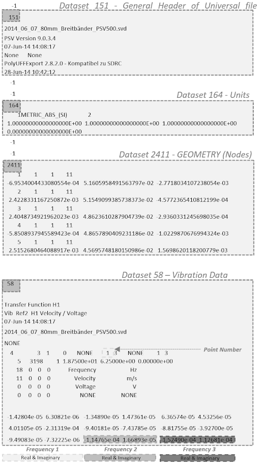
The structure of this data is built in data blocks. The first block includes the measurement points of the loudspeaker scan. After that there is one vibration data block for each point. The universal file format is developed by the Structural Dynamics Research Corporation (SDRL). Detailed information and documentation can be found on the SDRL website.
Note
The dataset 58 of the universal file may contain different kinds of measured data and allows to export multiple datasets into one file. Make sure that in the exporting process the data is exported as Transfer function of Displacement, Velocity or Acceleration to Voltage. Please keep in mind that large files will increase the computation time. To speed up the computation process, please export only one valid set of transfer functions and avoid data sets containing other unnecessary data.
Malfunction and Troubleshooting#
Overview#
This chapter will provide information that can help you solve common problems that occur with the Poly2SCN module. The software generates a variety of warnings automatically if malfunction is detected.
If you cannot find a description here that matches your problem, try these options:
Error and Warning Messages#
Wrong file extension.#
- Cause:
The file selected for Klippel Geometry data import has the wrong file extension
- Remedy:
Choose a file with the file extension “.sce”.
The imported file does not contain valid geometry data.#
- Cause:
The selected Klippel Geometry data import does not contain valid geometry data.
- Remedy:
The chosen Klippel Scanner file must be exported in the Klippel SCN – Scanning Vibrometer software. Open the file containing the Klippel scan results. Click on Export to open a drop-down menu and select Export ASCII… Select Polar Grid (r, phi, z) and Interpolate Data (original grid). Click on Start and complete the export process of the geometry data. The exported file can now be used with the Poly2SCN module.
Could not load valid geometry data. The number of points must be at least 10!#
- Cause:
The imported geometry data (Polytec or Klippel) has less than 10 points. For the interpolation process a geometry with at least 10 points is needed.
- Remedy:
Increase the spatial resolution of the Polytec measurement or Klippel geometry scan.
The imported geometry data is collinear!#
- Cause:
The interpolation process cannot handle collinear data. The reason for geometry data to be collinear may be a corrupt file or an insufficient measurement grid (all points on a straight line).
- Remedy:
Check the integrity of the UFF-file or Klippel geometry. If the data in the file is corrupted, try to repeat the respective export process. If the measurement grid of the Polytec measurement is insufficient, the measurement has to be repeated. The measurement grid must have points more regularly distributed on the surface to measure the distributed vibration pattern.
No valid geometry data found in specified file.#
- Cause:
The loaded UFF-file does not contain a valid data set defining the geometry of the measured grid.
- Remedy:
Make sure that the exported UFF-file contains a valid data set 2411 with the geometry data of the measured grid.
The loaded file contains more than one unique and valid data set.#
- Cause:
The loaded UFF-file contains multiple valid sets of vibration to voltage transfer functions (e.g. displacement transfer function with reference channel Ref1 and Ref2).
- Remedy:
Repeat the UFF-export and make sure to only export the set of transfer functions with the desired reference.
The loaded file does not contain valid data!#
- Cause:
The loaded UFF-file does not contain valid vibration to voltage transfer functions.
- Remedy:
Repeat the export process and make sure to export at least one of the following transfer functions.
Displacement/Voltage
Velocity/Voltage
Displacement/Voltage
The loaded file contains only spectrum data!#
- Cause:
The UFF-file only contains vibration spectrum data.
- Remedy:
Repeat the export process and make sure to export at least one of the following transfer functions.
Displacement/Voltage
Velocity/Voltage
Acceleration/Voltage
Inconsistent geometry and response data. Number of points is unequal.#
- Cause:
The number of points defined by the data set 2411 and the number of points defined by the transfer function data is unequal. The UFF-file may be corrupted.
- Remedy:
Repeat the UFF-file export process.
