
KCS Evaluation Tutorials#
Goal of This Guide#
This document describes how to evaluate the KLIPPEL Controlled Sound technology (KCS) by using the KLIPPEL QC measurement framework. The following topics are covered:
Requirements#
Note
Its mandatory to read the KCS Monitor manual which teaches necessary KCS basic knowledge before the KCS evaluation tutorials are executed!
Hardware#
KCS hardware platform - for example:
Nuvoton Audio Development Board (NAD)
Klippel Analyzer 3 (KA3)
APE Evaluation Board
Measurement Equipment. There are two options:
KA3 measurement device
Klippel Analyzer 3 (KA3)
Microphone
External USB sound devices
Klippel Dongle
External USB soundcard or USB microphone
Software#
Klippel dB-Lab of version >= 212.332
Licenses for: QC Standard 7 for KCS, SPL task, Multi-tone distortion task, SYN, 3DL
Additional License (only for QC measurement with external non-KLIPPEL USB audio device): QC no PA hardware required (== QC Standalone)
Klippel dB-Lab Operations#
KCS Monitor operation comprising initial data for the particular DUT
QC operation template KCS Evaluation Template.kdbx
Hardware Setup#
See also
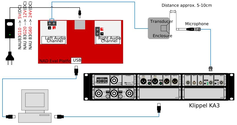
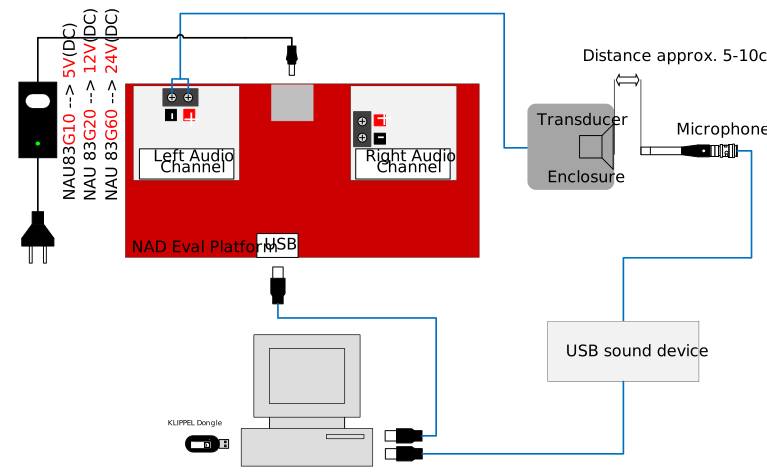
For pictures showing actual hardware, please see Hardware Connection.
There are different hardware setups dependent on the device on which KCS is running (KCS device) and what device is used as input device for the QC measurement (QC measurement device). Details about specific hardware setups applicable for your particular application are listed in the linked chapters below.
- Nuvoton Platform (NAD) as KCS Device
- Klippel KA3 (Internal AmpCard) as KCS Device
- Klippel KA3 (External Amp) as KCS Device
- Klippel APE EVB (Standalone Evaluation Board) as KCS Device
KCS Running on Nuvoton Platform (NAD)#
General System Overview#
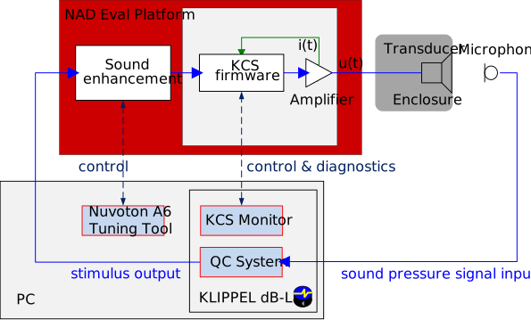
Hardware Connection - KA3 as QC Input Device#
Hardware Connection - Custom external USB sound interface as QC Input Device#
Warning
Using different audio devices for input and output will almost always lead to clock-drift. This affects distortion measurements requiring exact referencing to excitation frequencies. In multitone measurements this effect will generate virtual distortion which does not originate from the audio device. To avoid this problem, consider using a measurement setup on which audio output and input are running on the same clock. Otherwise, observe the frequency pattern of this virtual distortion, which is rising with frequency. Restrict the measurement frequency range to rather low frequencies in which this effect is not dominant yet. Often, measurements up to 1 kHz are possible.
KCS Running on Klippel Devices#
General System Overview#
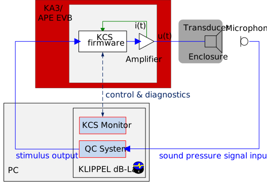
Hardware Connection - KA3 with AMP Card#
1.svg)
Hardware Connection - KA3 with External Amplifier#
1.svg)
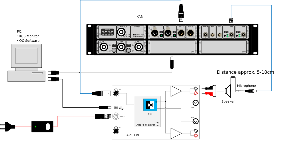
Hardware Connection - APE Evaluation Board#
Software Setup#
Ensure that the QC measurement device (KA3 or NAD board) is activated.
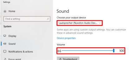
(only applicable for Nuvoton device): Ensure that the Nuvoton Audio Development Platform (NAD) is configured as active, default output device in Windows sound settings. Make sure the output is unmuted and the volume level is set to 100%.
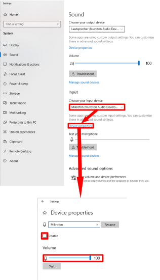
(only applicable for QC measurement with external non-KLIPPEL USB audio device): Ensure that your desired measurement hardware is configured as default input device in Windows sound settings. Make sure the input is unmuted and volume level is set to 100%.
Install dB-Lab as well as the provided license files and start dB-Lab after successfully performed installation process.
Configure the global inputs, outputs and calibrations to be used for QC measurement by performing following steps dependent on the used QC measurement hardware:
Applicable for KA3 used as QC input device
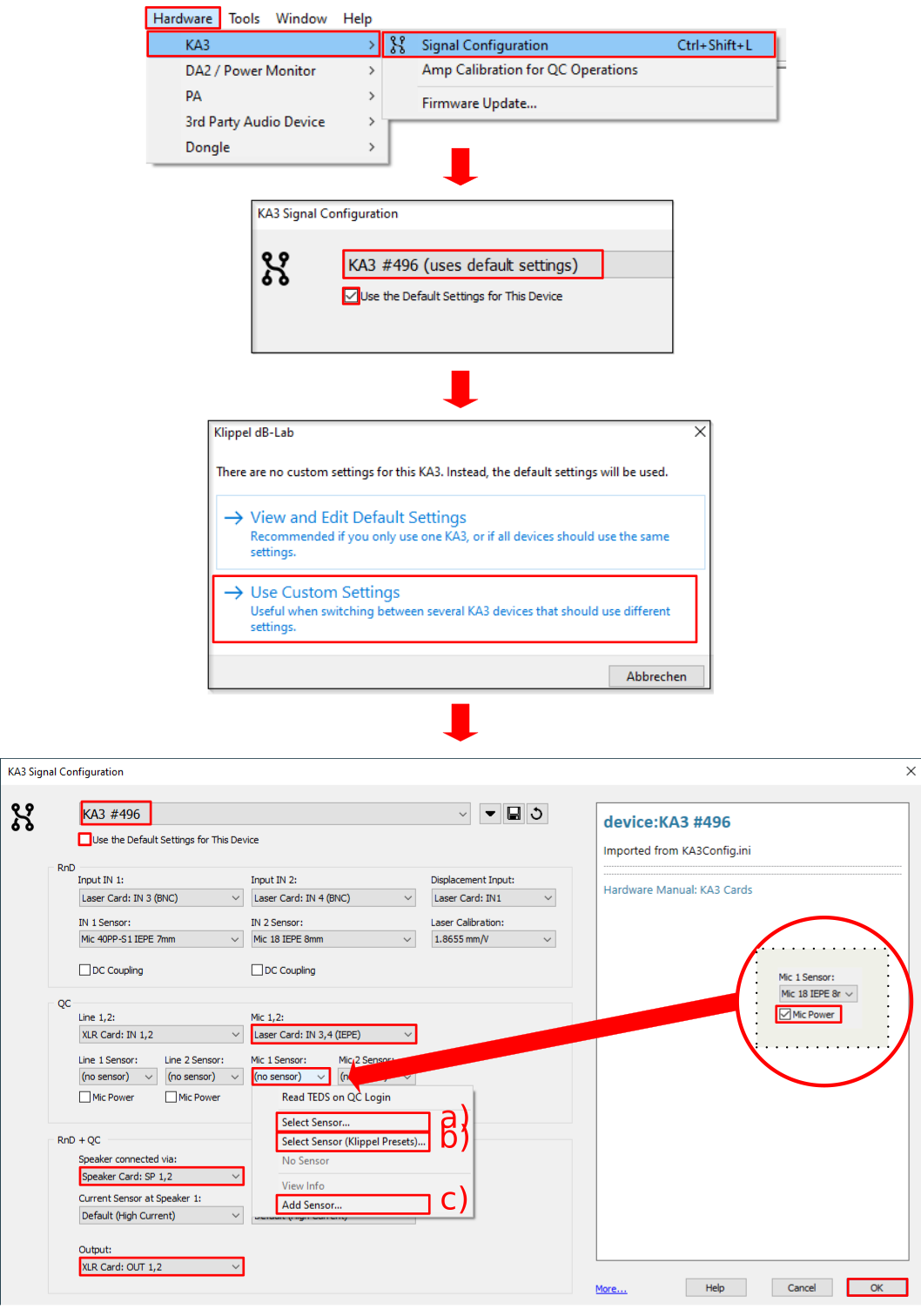
Select in menu: .
Select the specific KA3 to be used in device select drop-down menu and ensure that option Use the Default Settings for this device is un-checked.
Confirm the usage of a device specific custom setting in case the appropriate pop-up is displayed (will not be shown if checkbox was already unchecked in previous step).
Set Mic 1,2 Input in Section QC to Laser Card: IN 3,4 (IEPE).
Assign a microphone calibration file to Mic 1 Sensor by clicking on this input field to open menu and selecting one of the following options for assigning or creating a microphone calibration file:
- Select Sensors (Klippel Presets)…
Assign a pre-installed calibration file provided by Klippel for known/approved microphones by selecting appropriate file from subfolder Microphones in shown file selection dialog.
- Select Sensors…
Similar to previous option but an already existing user-created calibration file can be selected.
- Add Sensor…
Create a new calibration file (on using microphone calibrator or entering sensitivity and maximum sound pressure level manually) and assign this to the input.
Note
More details are available in the dB-lab help by clicking into Signal Configuration dialog and pushing F1 to open specific help content on topic microphone calibration.
Ensure to activate Mic Power associated with Mic 1 Sensor.
Configure Speaker connected via in section RnD + QC to Speaker Card: SP 1,2.
Configure Output in Section RnD + QC to XLR Card: OUT 1,2.
Push button OK to close Signal Configuration dialog and confirm settings.
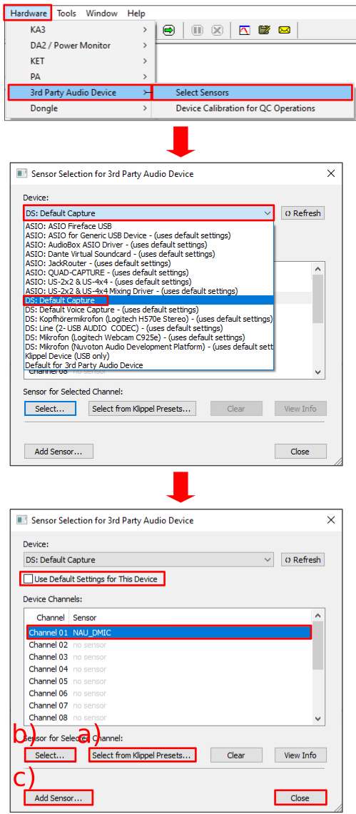
Applicable for custom external USB sound-interface used as QC input device
Select in Menu: .
Select the desired audio device in drop-down list Device.
Deactivate option Use Default Settings for This Device.
Assign a microphone calibration file to Channel 01 Sensor by highlighting this row with a mouse click and using one of the following buttons to select or create a microphone calibration file for this input:
- Select Sensors from Klippel Presets…
Assign a pre-installed calibration file provided by Klippel for known/approved microphones by selecting appropriate file from subfolder Microphones in shown file selection dialog.
- Select…
Similar to previous option but an already existing user-created calibration file can be selected.
- Add Sensor…
Create a new calibration file (on using microphone calibrator or entering sensitivity and maximum sound pressure level manually) and assign this to the input.
Note
For the Add Sensor process a new dB-Lab instance will be automatically opened:
Open the properties page of the QC operation of this newly opened database.
Navigate to tab QC Settings.
Push button Configure Hardware.
Ensure to un-check Use Default Devices and to select devices DS: Default Playback and DS: Default Capture as output and input device before the login to the QC calibration operation is initiated.
Close newly opened dB-Lab instance after calibration process is finished.
Further details about the microphone calibration process are available in the dB-lab help by click into Signal Configuration dialog and pushing F1 to open specific help content on the topic microphone calibration).
Close sensor file selection dialog
Note
Please ensure that your external audio device and microphone have sufficient SNR and input headroom for the task.
Open the database KCS Evaluation Template.kdbx in dB-Lab (dB-Lab instance further called db-Lab-QC).
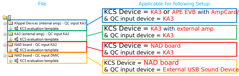
db-Lab-QC: Select the correct KCS evaluation template object based on your KCS device, amplifier type and QC input device for all subsequent steps of your evaluation process.
db-Lab-QC: Log in to one of both QC operations (dependent on tutorial, see appropriate chapters for details) located below the selected folder by selecting operation and pushing
 (Only
one active login to a qc operation possible at the same time. Log off from active QC operation
by pushing
(Only
one active login to a qc operation possible at the same time. Log off from active QC operation
by pushing  and log in to other QC operation to switch to that QC operation).
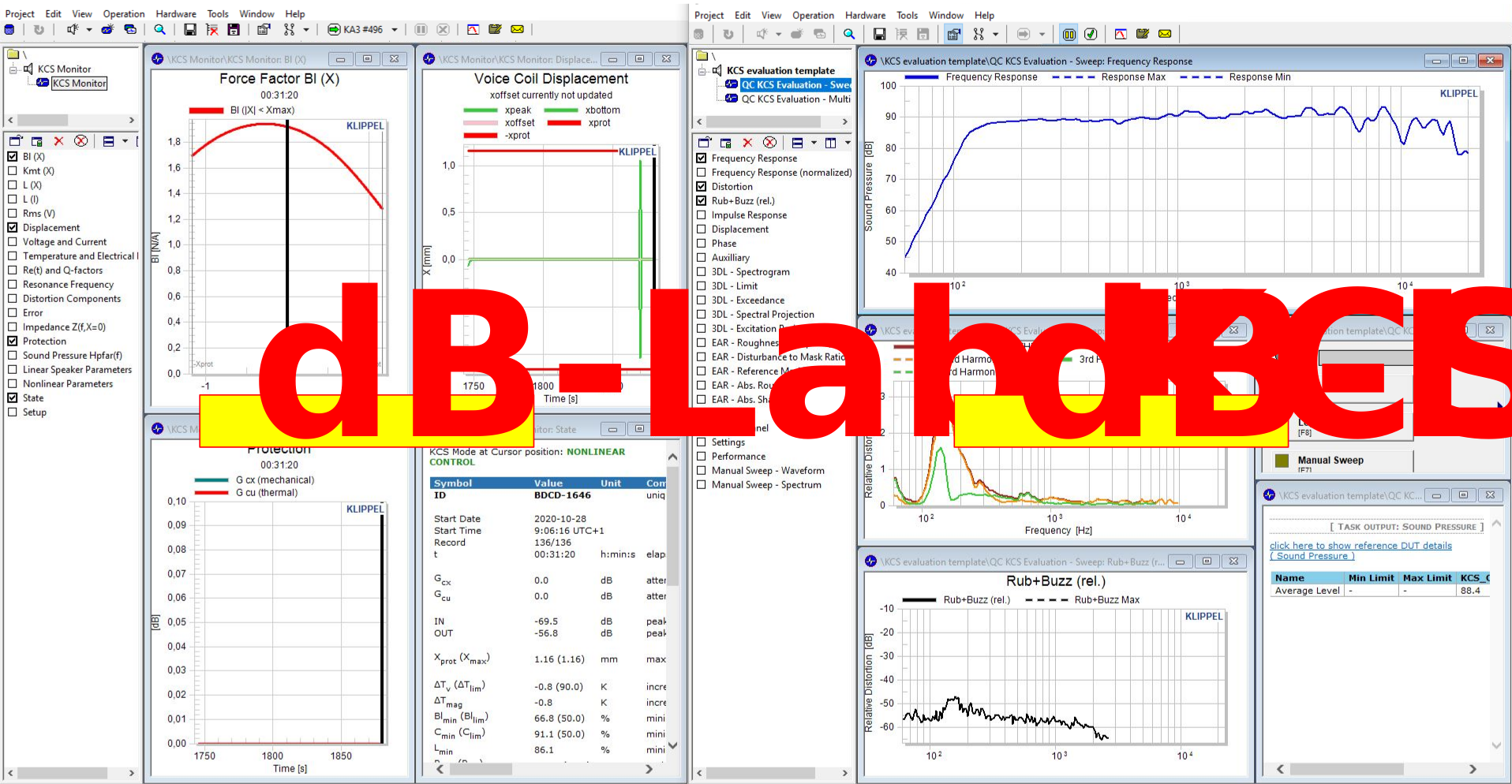
Open a second instance of dB-Lab and make sure the KCS Monitor operation belonging to the DUT is running in this dB-Lab instance. (This dB-Lab instance further called db-Lab-KCS).
Arrange the windows of both dB-Lab instances side by side.
Check Evaluation Environment Setup#
- Goal
Verify that the hardware and software setup is done correctly.
- Required QC Template Operation
QC KCS Evaluation – Sweep
Perform Setup Check#
db-Lab-KCS: Ensure that KCS control mode is
 (result window State).
db-Lab-QC: Perform a QC measurement (push button
 ) and carefully
listen to the audible sound output. All setup steps were done correctly, if short noise
signal followed by frequency sweep signal is audible and no error is shown in QC operation
summary window.
) and carefully
listen to the audible sound output. All setup steps were done correctly, if short noise
signal followed by frequency sweep signal is audible and no error is shown in QC operation
summary window.
Note
If error 70 occurs and no signal is audible at all, probably the speaker is not connected or a wrong speaker not matching the ID data is connected, the KCS operation is not running or the audio gain of the KCS operation or the stimulus level of the QC operation is set too low. This error also can occur if the wrong evaluation template not matching the correct hardware setup is used.
If error 70 occurs and only a short noise signal but no sweep signal is audible, probably the microphone is not connected/activated or IEPE/phantom power supply is switched off, a wrong microphone input is configured, the audio gain of the KCS operation or the stimulus level is set too low.
Tutorial 1 – Measure Frequency Response#
- Goal
Measuring the active speaker’s frequency response in the small signal domain using the Klippel QC – Quality Control system. This measurement can be used to set up the alignment and equalizer settings.
- Required QC template operation
QC KCS Evaluation – Sweep
Configure and Perform Measurements#
db-Lab-KCS: KCS should be turned on (result window State:
).Perform a QC measurement (db-Lab-QC:
). Make sure that the voice coil
displacement is considerably below the mechanical protection limit xprot (db-Lab-KCS: see
Displacement chart). If necessary, reduce the stimulus level of the Sound Pressure task.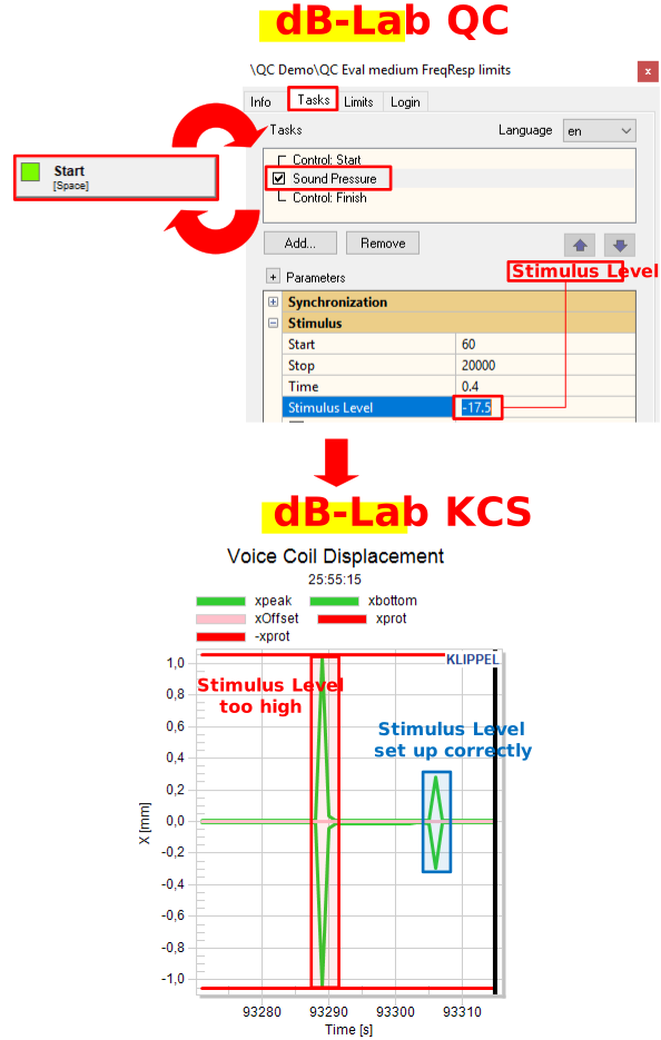
db-Lab-QC: The measured frequency response of the system in the small signal domain is shown in result window Frequency Response.
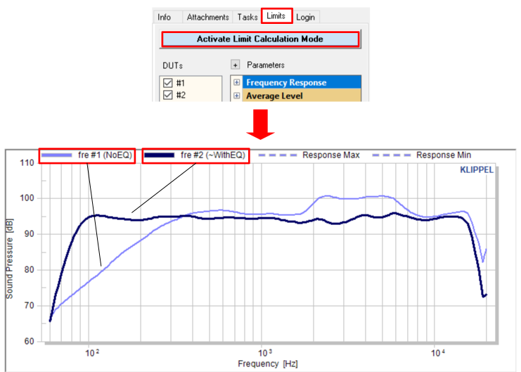
(optional) db-Lab-QC: Compare multiple measurements, e.g., taken at different microphone positions or to compare equalizer settings, by using the Limit Mode which overlays all measured curves. Navigate to the property page’s Limits tab and press Activate Limit Calculation Mode.
Tutorial 2 – Active Speaker Evaluation#
- Goal
Quick evaluation of the performance of the active speaker with and without KCS in the large signal domain.
- Required QC Template Operation:
QC KCS Evaluation – Sweep
Note
Perform this measurement with activated bass boost and equalization, comparable to the target application! Turn off nonlinear audio enhancement algorithms such as compressors and virtual bass as they produce nonlinear distortion, which would make it difficult to interpret the results.
Configure and Perform Measurements#
db-Lab-KCS: Ensure the KCS is switched on (result window State:
).db-Lab-QC: Perform a QC measurement (
). Adapt the stimulus level of the task Sound Pressure
in the property page until the voice coil displacement is close to the protection limit xprot
(db-Lab-KCS: see Displacement chart). Make sure that the protection system stays inactive
(db-Lab-KCS: see Protection chart).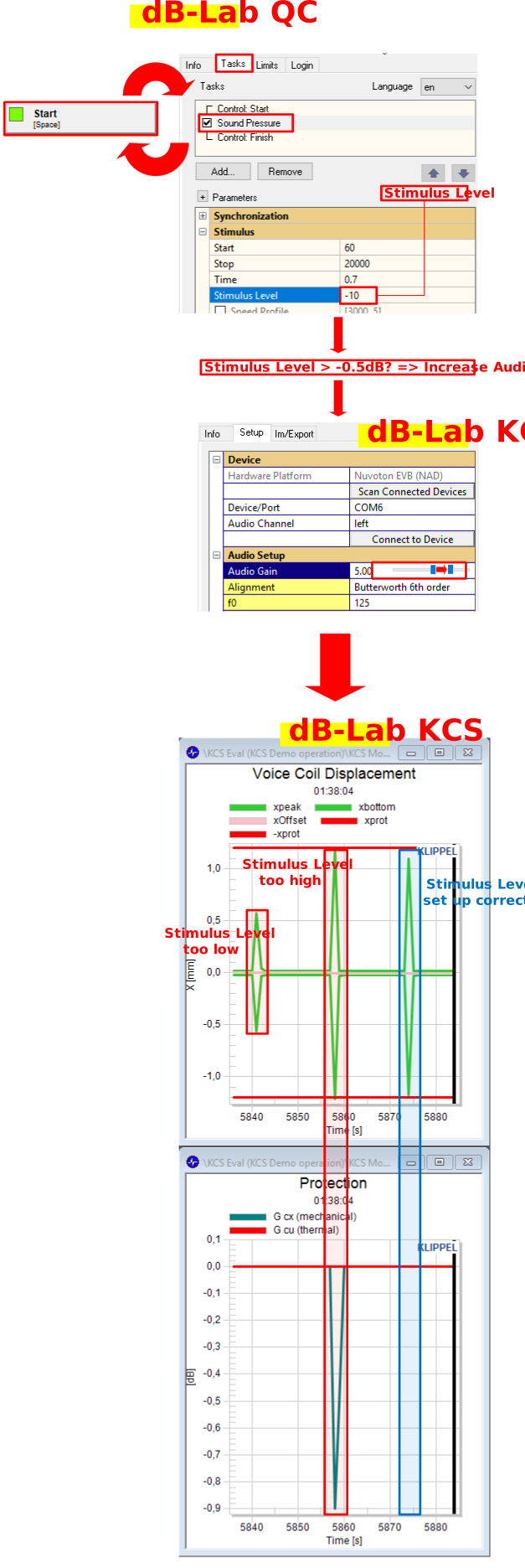
Note
The stimulus level of the SPL task must not exceed -0.5dB as clipping can occur. Increase the KCS Audio Gain (db-Lab-KCS: Property page) if more gain is required.
db-Lab-QC: Navigate to property page tab Limits and press Activate Limit Calculation Mode to easily compare measurements.
db-Lab-QC: Enter text “ON” into input field SN located in QC control panel and perform a QC measurement.
db-Lab-KCS: Switch to KCS-Mode
 .
.db-Lab-QC: Enter text “OFF” into input field SN located in QC control panel and perform a new measurement.
Note
Important: To get support from Klippel and for the KCS approval process you always need to provide the QC operation as well as the appropriate KCS Monitor operation containing measurement data.
Evaluating Results#
Rub & Buzz Curve#
- Objective:
This curve reveals irregular and impulsive distortion caused by e.g., rubbing or bottoming of voice coil, amplifier limiting, etc. This kind of distortion is very critical and must be avoided because of a low audibility threshold.
- Evaluation Step:
dB-LAB-QC: Check both rub & buzz curves shown in result window Rub+Buzz (rel.).
- Expected Result:
Neither of the curves exceed the limit of approx. -30dB which indicates high impulsive distortion. If the limit is exceeded, refer to section How to Treat Rub & Buzz Issues.
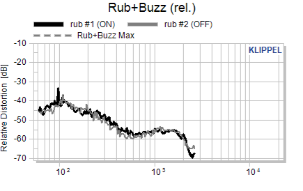
Figure 8: Example rub & buzz curves
Distortion Curve#
- Objective:
Verify that the active speaker system including KCS is working as expected. This includes:
Correct hardware connection
Initial KCS data fits to the speaker
KCS algorithm models the speaker correctly
- Evaluation Step:
dB-LAB-QC: Compare the total harmonic distortion curves shown in result window Distortion.
- Expected Result:
The THD measured in KCS ON mode should be lower than the THD measured with KCS in control mode KCS OFF + EQ.
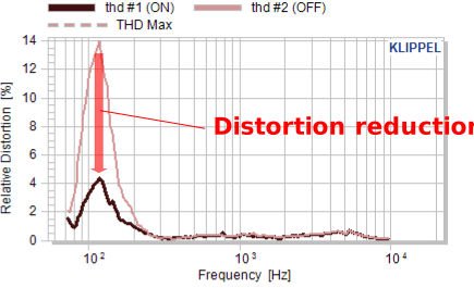
Figure 9: Example THD curves
Frequency Response Curve#
- Objective:
Symmetric speaker nonlinearities cause compression in the acoustical output at high voice coil displacement and/or velocity. Evaluate the KCS linearization feature which compensates these compression effects.
- Evaluation Step:
dB-LAB-QC: Compare the frequency response curves shown in Frequency Response window.
- Expected Result:
In the frequency range where the voice coil displacement and/or velocity is high, the magnitude of the frequency response in KCS ON mode is higher than without KCS. The curve shape is almost identical to the small signal measurement but with a higher level.
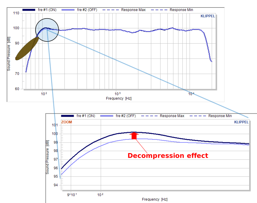
Figure 10: Example frequency response curves
Tutorial 3 – Evaluate Mechanical Protection System#
- Goal:
KCS prevents mechanical overload and allows to increase the SPL even if the transducer is already operated at its mechanical limits. This section explains how to evaluate the mechanical protection system.
- Required QC Template Operation:
QC KCS Evaluation – Sweep
Configure and Perform Measurement#
db-Lab-KCS: Ensure the KCS is switched on (result window State:
).db-Lab-QC: Perform a QC measurement (db-Lab-QC:
). Adapt the
stimulus level of the task Sound Pressure in the property page until the voice coil displacement
is close to the protection limit xprot, as explained in Tutorial 2 chapter
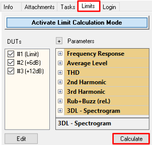
Configure and Perform Measurements).db-Lab-QC: Navigate to property page tab Limits and press Activate Limit Calculation Mode to easily compare measurements.
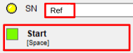
db-Lab-QC: Enter an identifier for the reference measurement, e.g., “Ref”, into the input field SN located in QC control panel and perform a QC measurement.
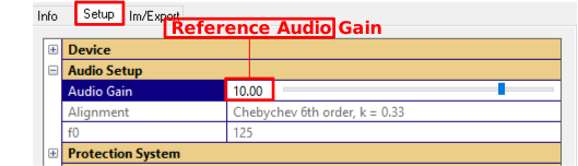
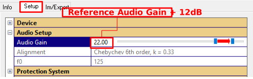
db-Lab-KCS: Open the property page and memorize the actual Audio Gain. This value will be referenced later as Reference Audio Gain.
db-Lab-KCS: Increase the Audio Gain by 6dB.
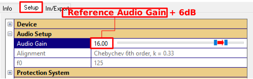
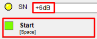
db-Lab-QC: Enter “+6dB” into input field SN located in QC control panel and perform a QC measurement.
db-Lab-KCS: Increase Audio Gain by further 6dB (Resulting Audio Gain = Reference Audio Gain + 12dB).
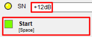
db-Lab-QC: Enter text “+12dB” into input field SN located in QC control panel and perform a QC measurement.
db-Lab-QC: Push button Calculate to update the values and curves displayed in the result windows.
Warning
Important: Reset the KCS Audio Gain (db-Lab-KCS) to the Reference Audio Gain after the measurement is performed otherwise the speaker can be easily damaged by accidentally applying a stimulus in mode KCS OFF + EQ.
Evaluating Results#
Frequency Response Curve#
- Objective:
Evaluate the influence of the protection system on the system’s frequency response.
- Evaluation Step:
dB-LAB-QC: Compare the three frequency response curves shown in result window Frequency Response.
- Expected Result:
Once the modeled displacement reaches the protection limit xprot, an adaptive high pass filter with variable cut-off frequency activates to prevent mechanical overload. The high frequency SPL is still increased in 6dB steps.
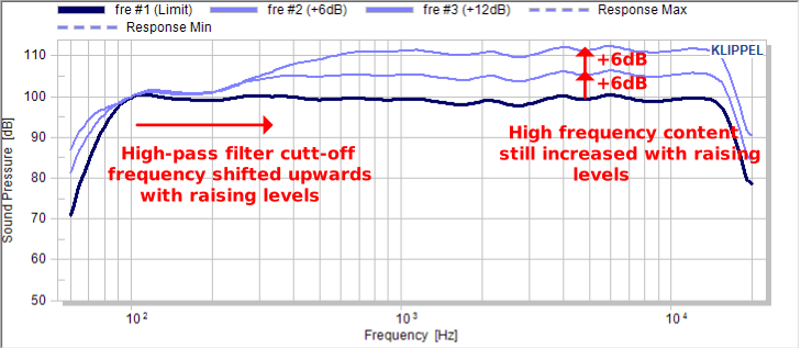
Figure 11: Example frequency response curves
Mean Sound Pressure Level#
- Objective:
Evaluate that the mean SPL can be further increased although the speaker already operated at its mechanical limits.
- Evaluation Step:
dB-LAB-QC: Compare the sound pressure level determined during the three measurements shown in result window Summary.
- Expected Result:
The mean sound pressure levels of the subsequently performed measurements increase on higher gain levels, even when the protection system was active.
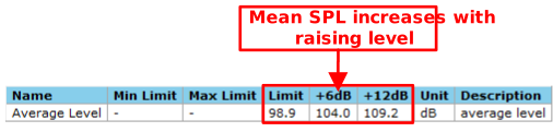
Figure 12: Example mean SPL values
Displacement and Mechanical Protection Curves#
- Objective:
Evaluate that the mechanical protection of the KCS ensures that the maximum defined working range is not exceeded and no mechanical overload situation occurs.
- Evaluation Step:
dB-LAB-KCS: Check the displacement curves xpeak/xbottom recorded during the three QC measurements and the appropriate mechanical protection curve G cx (mechanical).
- Expected Result:
The displacement did not exceed the defined working range limit xprot during the three QC measurements. The attenuation of the protection system agrees approx. to the attenuation at low frequencies (see Frequency Response Curve in dB-Lab-QC).
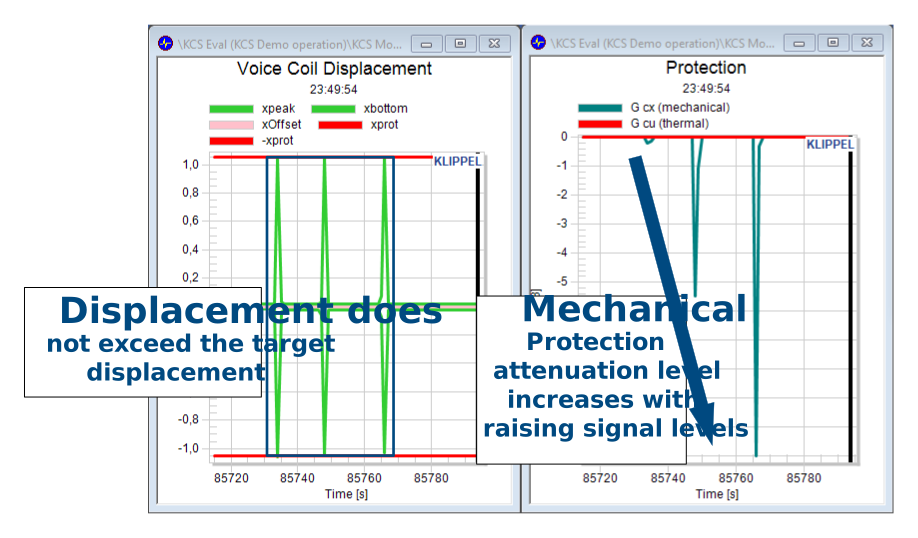
Figure 13: Example voice coil displacement and mechanical protection curve
Tutorial 4 – Multi-Tone Distortion#
- Goal:
Evaluate the reduction of harmonic and intermodulation distortion in the large signal domain on applying a multi-tone signal.
- Required QC Template Operation:
QC KCS Evaluation – Multi-tone
Configure and Perform Measurements#
db-Lab-KCS: Ensure the KCS is switched on (result window State:
).db-Lab-QC: The stimulus level of the task Multi-tone needs to be adapted similar as done with task Sound Pressure in Tutorial 2 chapter Configure and Perform Measurements) to achieve a maximum voice coil displacement without activating the mechanical protection. Therefore, perform a QC measurement (
) and adapt Stimulus Level in the property page of the
Multi-tone task until the voice coil displacement is close to the protection limit xprot
(db-Lab-KCS: see Displacement chart). Make sure that the protection system stays inactive
(db-Lab-KCS: see Protection chart).Note
The stimulus level of the Multi-tone task must not exceed -0.5dB as clipping can occur.Increase the KCS Audio Gain (db-Lab-KCS: Property page) if more gain is required.db-Lab-QC: After configuration of sufficient stimulus level, navigate to property page tab Limits and press Activate Limit Calculation Mode to easily compare measurements.
db-Lab-QC: Enter text “ON” into input field SN located in QC control panel and perform a QC measurement.
db-Lab-KCS: Switch to KCS-Mode
.db-Lab-QC: Enter text “OFF” into input field SN located in QC control panel and perform a new measurement.
Evaluating Results#
Multi-Tone Distortion Curve#
- Objective:
Speaker nonlinearities create harmonic and intermodulation distortion on applying stimulus signal containing multiple frequencies which are compensated by KCS.
- Evaluation Step:
dB-LAB-QC: Compare the multi-tone distortion curves shown in Multi-tone Distortion window.
- Expected Result:
The distortion measured in KCS ON should be reduced compared to the KCS OFF + EQ measurement.
Frequency Response Curve#
- Objective:
As already discussed in Tutorial 3 – Active Speaker Evaluation symmetric speaker nonlinearities will cause compression in the acoustical output at high voice coil displacement and/or velocity. Of course, the KCS linearization feature also compensates these compression effects in case of more complex stimulus signals are applied to KCS.
- Evaluation Step:
dB-LAB-QC: Compare the frequency response curves also shown in the Multi-tone Distortion window.
- Expected Result:
In the frequency range where the voice coil displacement and/or velocity is high, the magnitude of the frequency response in KCS ON mode is higher than without KCS.
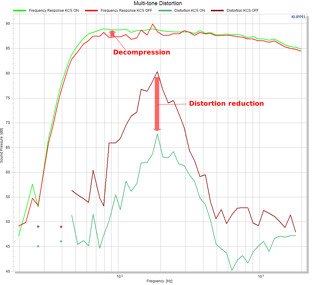
Figure 14: Example frequency response and multi-tone distortion curves
How to Treat Rub & Buzz Issues#
- Goal:
Identify and eliminate possible root causes for detected rub & buzz issues.
To determine root causes of the rub & buzz it is necessary to check the QC measurement and the corresponding KCS Monitor operation at the exact timestamp at which the stimulus was applied to the speaker.
Note
You can set the time cursor in any of the time-based curves of the KCS Monitor operation to get specific information for that timestamp by pressing CTRL + clicking in the window at the desired time.
Transducer Defect or Overload#
- Error
Rub & buzz is also present KCS OFF + EQ mode
Speaker is operated within the defined working range (xprot is not exceeded)
Level of environmental noise sufficiently low
Amplifier/output is not clipping
Input is not clipping
Acoustical output level is sufficiently high
- Solution
Use KCS Monitor parameter Excursion Limit to reduce the voice coil’s working range
Replace the speaker by a speaker without rub & buzz issues
Amplifier/ Output Limiting#
- Error
Warning Output clipping in KCS Monitor
KCS Monitor: OUT (State window) is very close to 0dB during applying stimulus
- Solution
Reduce usable working range of speaker by decreasing KCS Monitor parameter Excursion Limit (see Tutorial 5 – Protection and Limiter)
- Error
Required output voltage is larger than available rail voltage of the amplifier.
- Solution
Adjust limiter settings (see Tutorial 5 – Protection and Limiter)
Check voltage output from power supply (Hardware Connection)
KCS Input Clipping#
- Error
Warning External input signal is limiting displayed during applying stimulus
KCS Monitor: IN (State window) is very close to 0dB during applying stimulus
- Solution
If IN is close to 0dB reduce the input level (e.g., reduce gain in NuAudioA6 tool if used)
If IN is not close to 0dB reduce the Audio Gain in KCS Monitor property page
Environmental Noise#
- Error
Bad matching rub & buzz curves of subsequent measurements
- Solution
Reduce the environmental noise
Acoustical Output Too Low#
- Error
Acoustical output of the speaker is barely audible
Noisy Frequency Response curve
- Solution
Increase the stimulus level
KCS Protection System#
- Error
None of the above reasons apply
- Cause
The rub & buzz measurement is very sensitive and reveals small changes of the signal created by the protection system.
- Solution
If critical, increase the Protection Delay in KCS Monitor or reduce bass boost. Usually this kind of distortion is not audible with music/speech signals if Protection Delay is greater than 2ms.
