
DOC – Documentation#
DOC Tutorial#
Introduction#
The DOC module is meant to add a documentation to an object or an operation. The module provides the possibility to fill in a predefined editable documentation which satisfies the IEC 60268‑5, ‑21 and IEC 60268‑22 standards. Several templates are given to speed up the documentation process.
The DOC module also enables users to import an externally prepared documentation, which will be displayed by the DOC module.
Furthermore, any file can be saved as attachment to a DOC operation. This may be used to add data sheets and additional information to an object or an operation.
Goals of the Tutorial#
The tutorial will provide an overview of the functions of the DOC module. Especially the usage of the three key functionalities of the DOC module will be taught:
Editable Documentation
Import Documentation File
Attachments
Part 1: Editable Documentation#
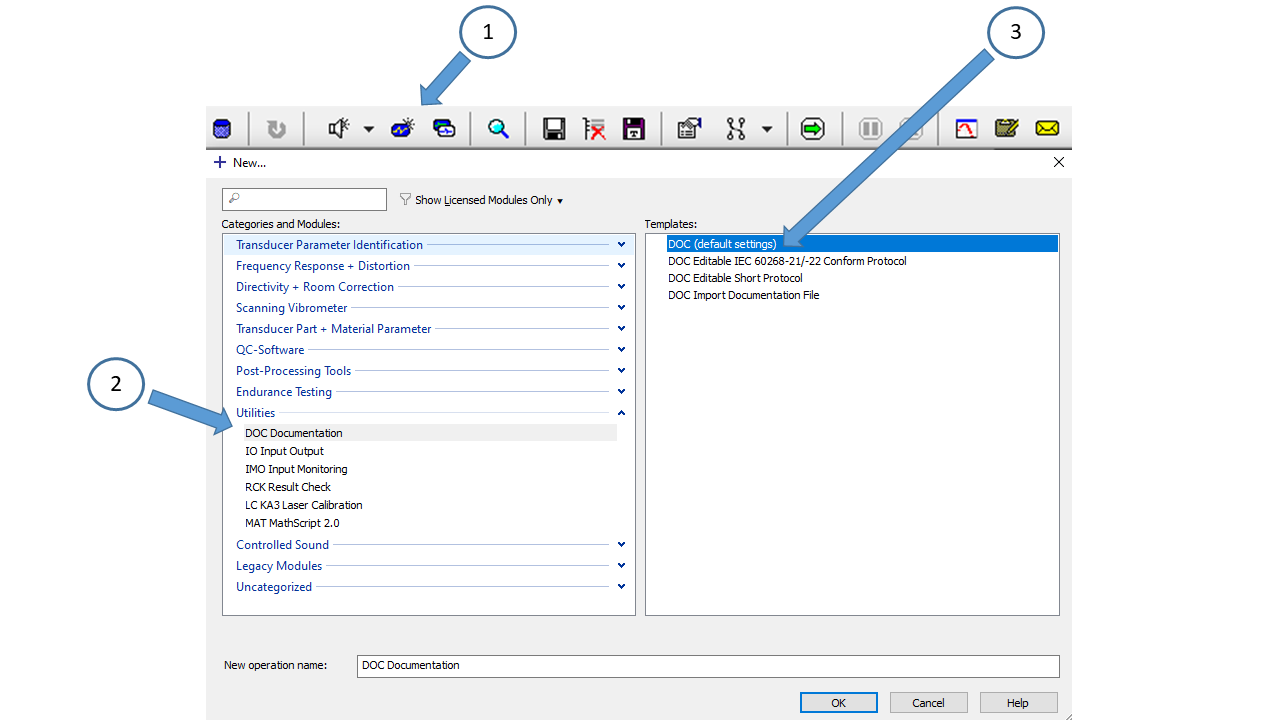
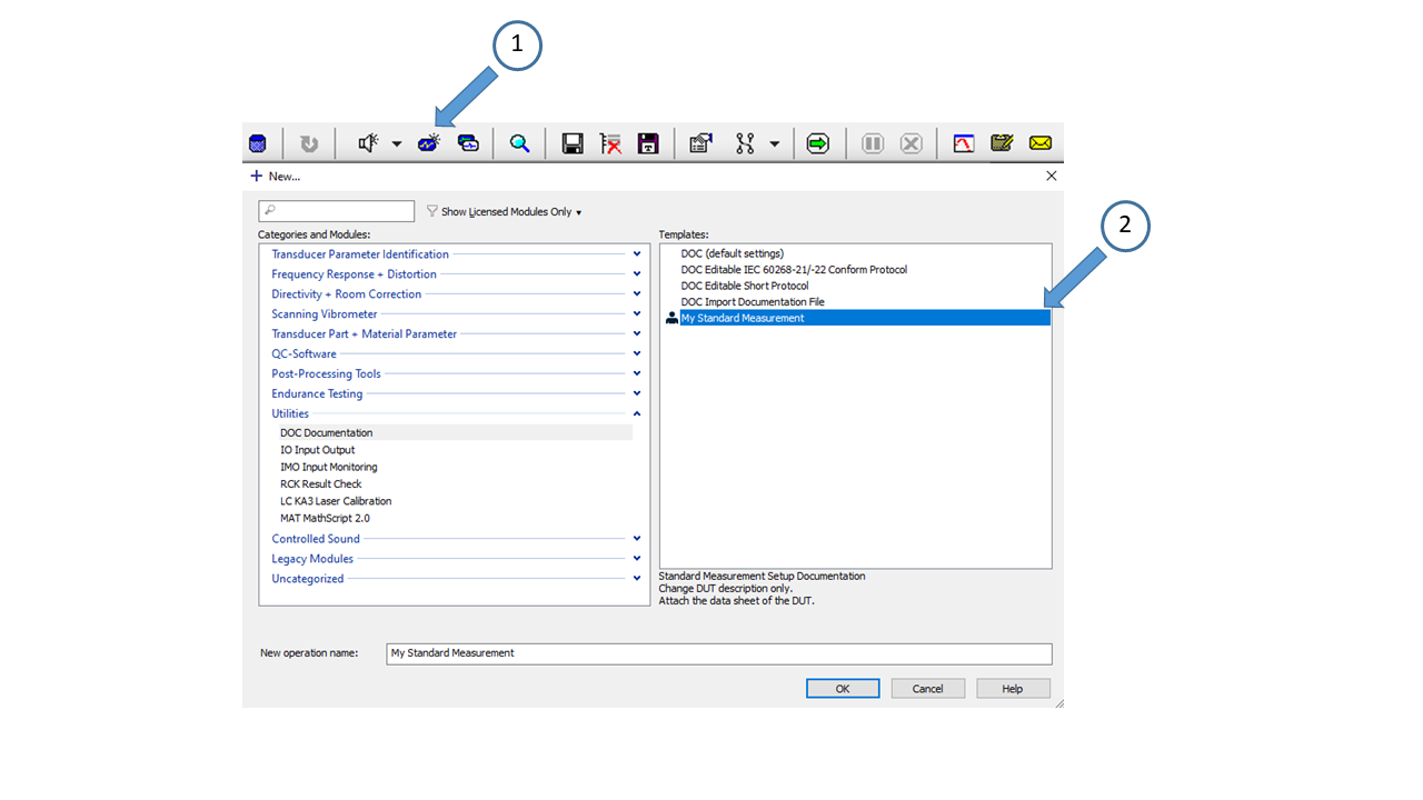
Create a new DOC module by clicking the New Operation  icon in the toolbar. The DOC
module is then found in the category Utilites. There are three templates available
icon in the toolbar. The DOC
module is then found in the category Utilites. There are three templates available
DOC (default Settings) |
Default DOC operation. |
|---|---|
DOC Editable IEC 60268-21/-22 Conform Protocolr |
This template includes all the entries relevant for an IEC 60268-21/-22 conform documentation. |
Editable Short Protocol |
This template contains only the most important entries. |
Import Documentation File |
This template can be used if a documentation file should be used instead of the editable documentation. |
Note
It is recommended to create your own templates to minimize the necessary effort to document a measurement (See also Creating a Template for Future Use)
For this tutorial the DOC (Default Settings) template should be used. Add the template by double clicking on the template.
An example for an editable documentation is given in the Web Example Database.
Example data used in this manual is stored in the Web Example database. If not downloaded already, get it from the latest R&D release <https://www.klippel.de/go/current-rnd-release> and open the web-based database.
See also
View Results for general information on how to download this database, open and view results in dB-Lab.
Select the folder Documentation (DOC). Then select the object Passive Headrest Module and select the operation DOC Headrest Module.
Remove/Add Entries#
The first step is to include or exclude entries from the documentation. Open the property page of the DOC operation. By default, the documentation mode is set to Editable Documentation and the Edit Mode is set to Engineer. In the property page category Documentation, the individual items of the documentation can be edited.
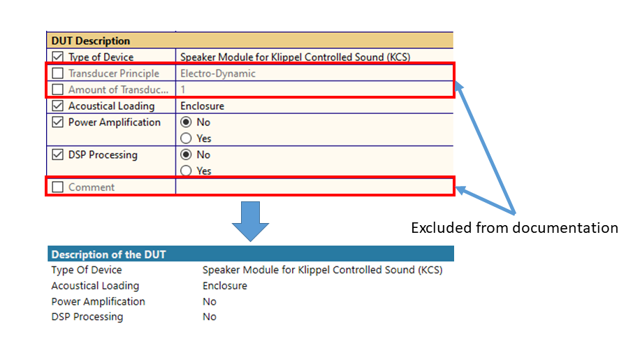
Each entry has a checkbox to enable/disable this parameter. If a parameter is disabled, it is not included in the documentation displayed in the Documentation window. If each parameter of one category is disabled, the whole category will be excluded from the display in the Documentation window. In the Edit Mode Engineer the checkboxes can be used to enable/disable parameters. Enabling/disabling parameters is prohibited in the Edit Mode Operator. Thus the Edit Mode Operator mode should be used when working with custom templates to make sure no entries are excluded by accident.
Adding Images#
The Editable Documentation gives a user the possibility to add two images. The first one is found in the category Documentation Title.
The image can be added using the parameter Image (DUT) and is meant to contain an image of the device under test (DUT). Supported file types are: .jpg, .jpeg, .png and .gif. The size of the image displayed in the Documentation window can be altered using the parameter Image Width. Additionally, a caption may be added.
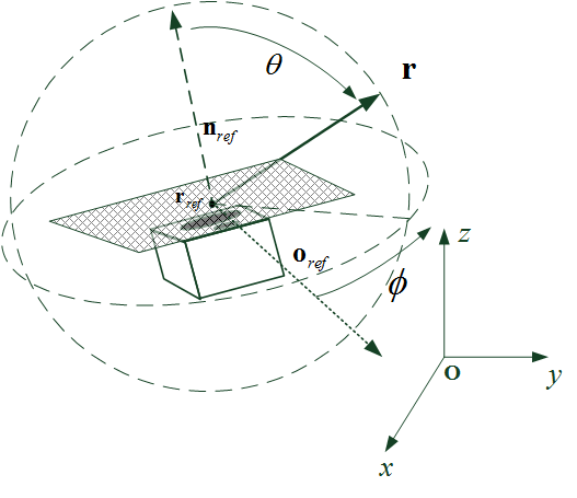
The second possibility to add an image is found in the category Positioning of the DUT with the parameter Image (Setup). This image is meant to illustrate the positioning of the DUT and should incorporate the reference point, axis or area and the normal and orientation vector as stated in the IEC 60268-21 or IEC 60268-22 standards. Example image:
Note
If the imported image has the wrong orientation, it might help to use an image editor to rotate and save the image to get rid of meta data. The imported images are listed in the Attachments window.
Additional Comments and Custom Entries#
The DOC module has the option Custom in each drop-down menu except for the parameter Image Width. Using the Custom option any user defined description or value can be added.
For each category there is an additional Comment parameter to add additional information to the category. In these parameters a line break can be added using the token \n.
Creating a Template for Future Use#
It is recommended to create your own templates for the Editable Documentation for standard measurements. This way the user does not have to enable/disable all needed parameters and can reuse the entries that will not change for another DUT. In this case we create a template called “My Standard Documentation”. Open the property page category Mode and select the Edit Mode Operator.
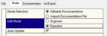
By doing this disabling parameters is prohibited. Then click the Save as Template icon in the toolbar.

Enter a name for this template and a comment. Now the template is available in the Template list of the DOC module. The user created templates can be identified by the symbol added at the left side in the template list. Double click the user created template to create a DOC module based on the template.
Part 2: Import Documentation File#
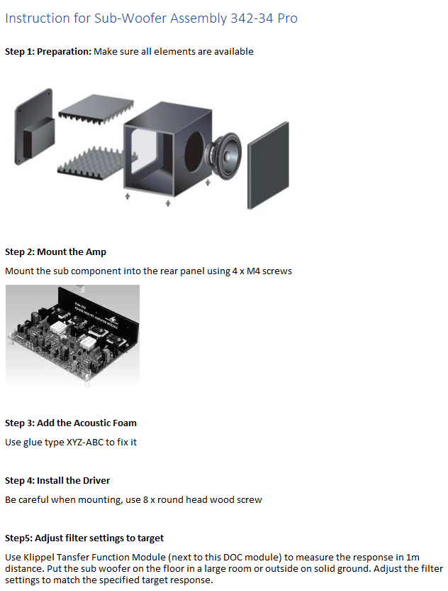
Create a new DOC module by clicking the New Operation icon. The DOC module is found in the category Utilities. An example is given in the web example database. Select the folder Documentation (DOC) then the object Sub Woofer Assembly and select the operation DOC Sub Woofer Assembly.
Add a Documentation File#
The DOC module provides the option to upload a documentation file. The upload of a documentation file is meant to give more freedom to the user than given in the mode Editable Documentation. The supported file types are: plain text .HTML, .HTM, .TXT, .JPG, .PNG. These files can easily be generated with third party software.
Note
Only plain text .HTML, .HTM files are supported. Others may lead to unexpected behavior.
To add a documentation file the mode found in the property page category Mode has to be set to Import Documentation File. The documentation file can then be added using the parameter Documentation File which is found in the property page category Documentation.
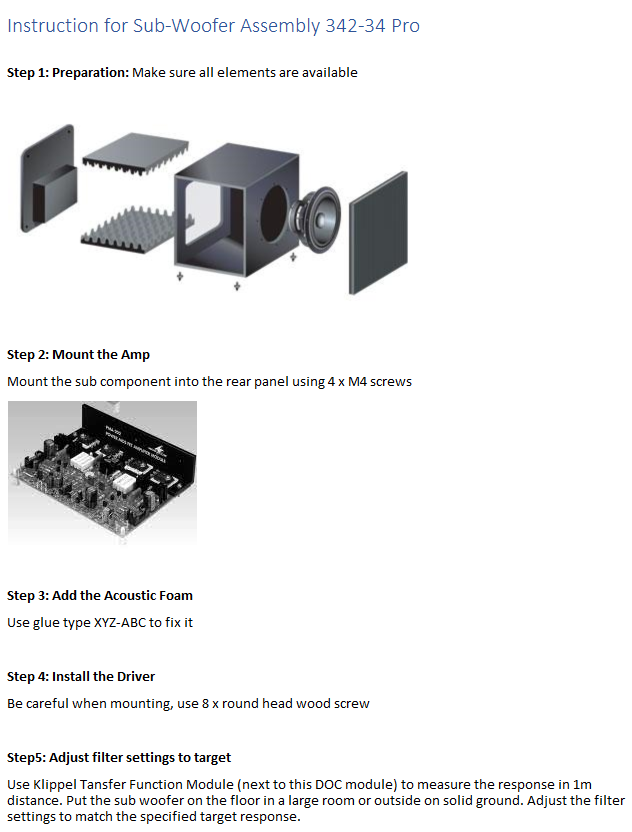
The uploaded file is then displayed in the Documentation window. An example of a user defined HTML instruction is given below.
Note
The imported documentation file is listed in the Attachments window.
Part 3: Attachments#
The DOC module provides an attachment container so that the user may add arbitrary attachments to the operation. This can be used to add data sheets, additional documents and images. This makes it possible to send the attachments along with the database. Thus, a user receiving and opening the database can access all the data attached to the DOC operation.
Open the Web Example Database. Select the folder Documentation (DOC). Select the object Multiple Attachments and select the operation DOC Multiple Attachments.
Add an Attachment#
To add an attachment, open the property page category Documentation. The last category (Attachments) of this property page contains the parameters that are meant to add an arbitrary attachment to the DOC operation.
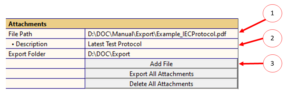
Use the parameter File Path to enter the path of the file to be attached to the DOC operation.
The parameter Description can be used to add a description which will be displayed in the Attachments window (optional).
To finally attach the file to the DOC operation, use the button Add File. The added attachments can then be seen in the Attachments window.
Export Attachments#
The DOC module provides the export of a single attachment or all attachments. The first step for both export possibilities is to specify an export folder using the parameter Export Folder.
Export Single Attachment#
A single attachment can be exported using the Attachments window if an export folder is specified. For each attachment there is a Save As option in the Attachments window.
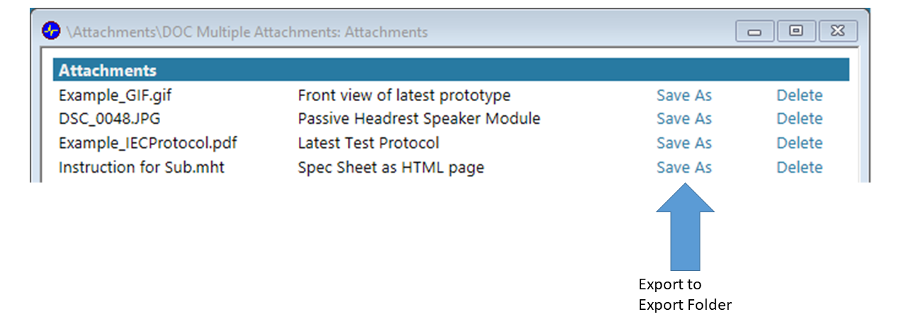
Upon clicking the Save As option the attachment associated with this button will be exported to the specified export folder. If there is already a file having the same name a message box will be displayed asking whether the file should be overwritten.
Export All Attachments#
All attachments can be exported using the button Export All Attachments if an export folder is specified. The Export All Attachments button is found in the category Attachments in the property page category Documentation.
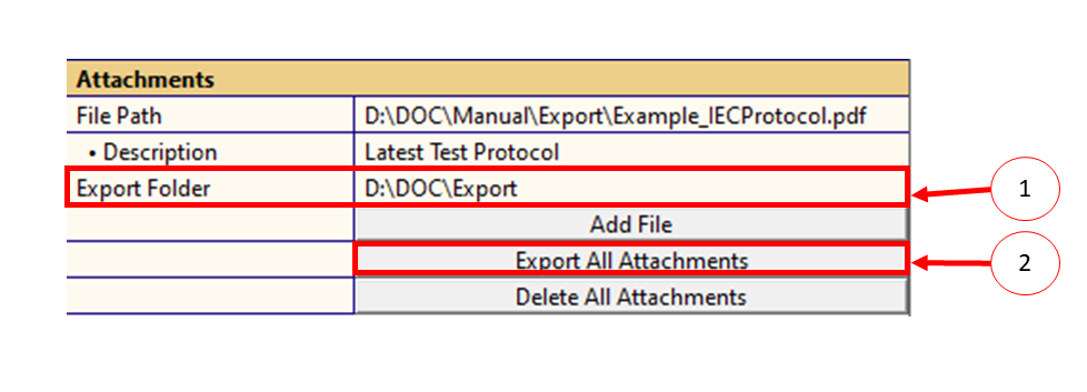
Upon clicking the Export All Attachments button all attachments listed in the Attachments window are exported to the export folder. If there is already a file having the same name a message box will be displayed asking whether the files should be overwritten.
Delete Attachments#
The DOC module provides the possibility to delete a single attachment or all attachments.
Delete Single Attachment#
A single attachment can be deleted using the Attachments window. For each attachment there is a Delete option.
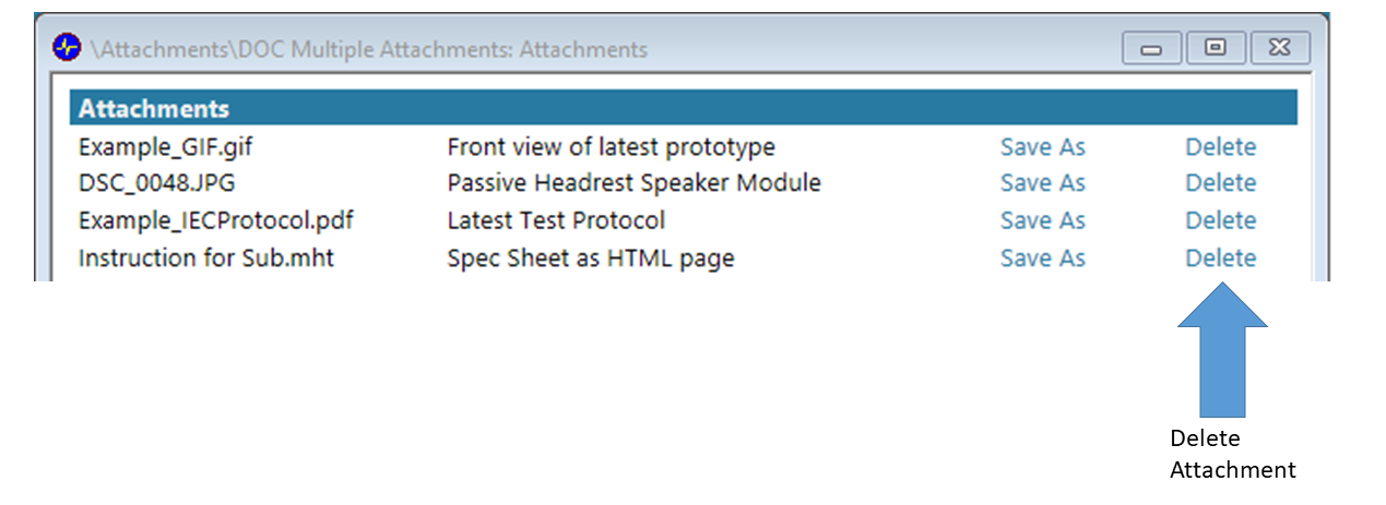
By clicking the Delete option the attachment associated with this button will be deleted.
Note
Be careful, there is no undo available, if an attachment is deleted.
Delete All Attachments
All attachments can be deleted by using the button Delete All Attachments. This button is found in the category Attachments in the property page category Documentation.
Upon clicking the Delete All Attachments button all attachments listed in the Attachments window are deleted.
Note
Be careful, there is no undo available, if all attachments are deleted.
DOC Reference#
Overview#
The Documentation (DOC) module simply describes tests and can be used to store related documents. It does not measure itself. It complements the measurement and simulation modules of the Klippel Analyzer system. It has 3 basic functions:
Documentation according to IEC 60268-5, 21 and 22 with pre-defined attributes. User defined templates can be used to meet company specific extent of attributes, that need to be stated.
Use instruction or documentation files using user defined style and content (.HTML, .TXT, .JPG, .PNG).
Attachments: Storing documents (any file type) to be kept in database for easy and comprehensive exchange of test results with related information. The DOC module acts like a container for those files. They are not visualized nor interpreted, they can be simply stored to and fetched from a database.
An HTML chart Documentation shows the compiled documentation or the user defined HTML file. Reports and PDF output can be created using the dB-Lab report generator.
Reports on object level (combining multiple operations) may be used to combine the output of the DOC module with actual test results of other operations.
Property Pages#
Property Page: Mode#
Mode Selection#
The DOC module offers two modes:
- Editable
This mode provides a predefined framework for a documentation fulfilling Documentation IEC 60268 standards. Parameters, specified by those standards to describe a DUT or measurement, are given to fill in the documentation displayed in the Documentation window. The Editable Documentation mode provides the possibility to include two images. Additionally, arbitrary files may be attached to the operation.
- Import Documentation File
This mode gives more flexibility since a user defined documentation file may be imported which will be displayed in the Documentation window. The supported file types are: plain text .HTML, .HTM, .TXT, .JPG, .PNG
See also
Note
Only plain text .html, .htm files are supported. Others may lead to unexpected behavior.
Edit Mode#
The documentation module offers two edit modes that have an effect on the Editable Documentation mode. The Edit Mode is only visible if the Editable Documentation is selected.
- Engineer
This mode enables the user to select parameters to be included in the Editable Documentation. This mode is meant to customize the required entries of the documentation. The selection is done by deactivating/activating the checkboxes of a parameter. Every activated parameter will be included in the Documentation window.
- Operator
The Operator mode should be used to fill in the Editable Documentation. When the Operator mode is selected, the user cannot activate/deactivate parameters. Deactivated parameters are not visible in Operator mode and are not included in the documentation.
Auto Update#
This checkbox is ticked by default. If this checkbox is ticked, the Documentation window will be
updated after any change done in the property page Mode. When the Auto Update checkbox is
not ticked, the update of the Documentation window can be triggered manually by pressing the
Run button  . This makes changing the parameters in the property page Documentation
faster.
. This makes changing the parameters in the property page Documentation
faster.
Property Page: Documentation#
Select the required mode as described above on the property page category Mode using the Mode Selection parameter.
Mode: Editable Documentation#
Using the Editable Documentation mode each parameter may be switched on and off, including or excluding it from the documentation displayed in the Documentation window.
It is highly recommended to store templates of the company specific extent of documentation for general measurements.
Each category of the property page Documentation has an additional Comment parameter to enter further information to this category which might be required in addition to the predefined items.
Any parameter asking for a text input can decode a line break using the token \n which is displayed in the Documentation window.
Documentation Title#
This category serves to change the title section of the documentation. The title and subtitle may be changed and an image may be uploaded. Supported file types for the image are: .JPG, .JPEG, .PNG, .GIF. An introductory comment may be added as well.
Note
There is a size limit of 100 MB for each image. If the imported image has the wrong orientation, it might help to use an image editor to rotate and save the image to get rid of meta data.
DUT Description#
This category contains information about the DUT provided by the manufacturer.
Physical Characteristics#
The physical characteristics contain the mass, the outer dimensions and information about the cables and connectors. If the documentation should satisfy the IEC 60268-21 or -22 standards, the outer dimensions shall be specified in accordance to the IEC 60268-14 standard and the cables and connectors should satisfy the requirements of the IEC 60268-11/-12 standards.
Conditions#
In accordance to the IEC 60268‑21 standard the Max. Sound Pressure Output or the Max. Input Value rated by the manufacturer shall be specified. Additionally, the climatic conditions have to be documented. The following climatic conditions are required:
Temperature: 15 °C to 35 °C
Relative Humidity: 25 % to 75 %
Barometric Pressure: 86 kPa to 106 kPa
In this category the user may choose between the climatic conditions required by the standard, a reference to actual measurement operations or a custom climatic condition.
The standard measurement conditions required in IEC 60268 standards consist of (may not be complete):
Mounting of the DUT (e.g., fulfilling clause 13 of IEC 60268-21/-22)
Acoustical environment (e.g., satisfies clause 9 of IEC 60268-21/-22)
Noise should be kept at lowest possible level. Measurement data which is less than 20 dB above the noise floor has to be marked as corrupted by noise.
Positioning of the DUT (e.g., satisfies clause 10 of the IEC 60268-21)
The DUT has to be acclimatized to the ambient climatic conditions.
The DUT has to be allowed to cool down between successive tests as soon as the amplitude compression exceeds 0.5 dB.
Test signals (e.g., satisfy clause 8 and 16 (rated frequency range) of IEC 60268-21)
Any active control element has to be set to its neutral setting. If that’s not the case, the active control elements deviating from the neutral setting shall be documented.
Used measurement equipment (e.g., specified in clause 11 of IEC 60268-21)
Any deviation from the normal measurement conditions has to be documented.
Preconditioning#
Some standards require preconditioning of the DUT, since permanent changes of the DUT may occur when signals resulting in high displacement are used for the first time. The preconditioning Signal, Level and Time can be documented in this category.
Acoustical Environment#
The acoustical environment can be documented in this category. Depending on the chosen acoustical environment, the limitation of the assumed acoustical environment should be documented as well (Valid Frequency Range, Lower Limiting Frequency and Measurement Impairing Conditions).
Positioning of the DUT#
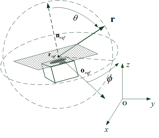
The positioning of the DUT includes the definitions of:
reference point \(\mathbf{\text{r}}_{\text{r,ref}}\)
normal vector \(\mathbf{\text{n}}_{\text{r}}\)
orientation vector \(\mathbf{\text{o}}_{\text{r}}\)
Those can be shown best using the provided image import. This image should describe the setup including definitions mentioned above.
Note
If the imported image has the wrong orientation, it might help to use an image editor to rotate and save the image to get rid of meta data.
Additionally, the Evaluation Distance and the Measurement Distance can be documented in this section to meet the requirements of the IEC 60268-21 standard.
Measurement Equipment#
The used microphone and/or laser can be specified in this category. Alternatively, a reference to a measurement can be made. A reference to a measurement will be displayed with the entry “See Measurements” in the Documentation window.
When one of the provided label options is chosen, the type (for microphones) and the sensitivity will be filled in automatically. The sensitivities of the microphone and the laser give information about the measurement uncertainty. Additional labels and types can be added by using the “Custom” option.
Mounting of the DUT#
The way the DUT is mounted can be specified in this category. The provided choices consist of Klippel hardware and the mounting options required by some standards.
Mode: Import Documentation File#
A user defined documentation file may be imported. The imported file will be displayed in the Documentation window. The supported file types are: plain text .HTML, .HTM, .TXT, .JPG, .PNG. The documentation file can be created with third party software.
Note
There is a size limit of 100 MB for each file. Additionally, only plain text .HTML,.HTM files are supported. Others may lead to unexpected behavior.
Attachments#
This category allows attaching arbitrary files to the DOC operation, exporting them into a specified Export Folder and deleting all attachments including the images and Documentation File. An optional Description may be added to the files to be attached. The Description must be entered before adding the file by clicking the Add File button.
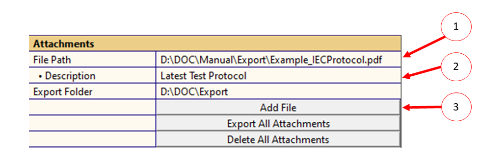
The added attachments including the images and the Documentation File are listed in the Attachments window. Inside the attachment window the options Save As and Delete are found. Upon clicking the Save As option, the related attachment is exported to the folder specified in the Export Folder parameter. Upon clicking the Delete option, the related attachment is deleted.
Additionally, all attachments can be exported to the specified Export Folder by using the button Export All Attachments in the property page Documentation. The button Delete All Attachments deletes all attachments listed in the Attachments window.
Note
There is no undo available, if an attachment is deleted.
Result Windows#
Documentation#
The Documentation window displays the documentation depending on the chosen mode selected via
the parameter Mode Selection. The Documentation window can be refreshed when pressing the
Run button
.
Mode Selection: Editable Documentation#
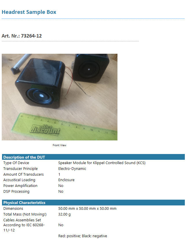
In this mode the predefined documentation is displayed. Any parameter with a ticked checkbox will be included in the Documentation window. The order of the entries in the Documentation window is equal to the order of the parameters in the property page. An example is given below:
Mode Selection: Import Documentation File#
In this mode the imported documentation file specified by the parameter Documentation File is displayed in the Documentation window. An example is given below:
Attachments#
The Attachments window lists all attachments of a DOC operation including
imported images in the Editable Documentation mode and
documentation files specified using the Import Documentation File mode.
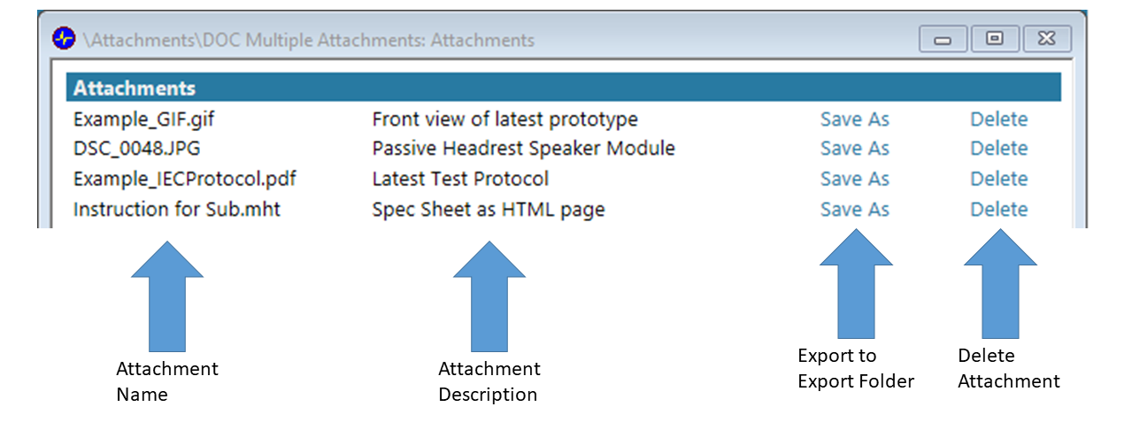
The Attachments window also provides the possibility to export single attachments using the Save As option. The attachments will be exported to the Export Folder. Additionally, the Attachments window also provides the possibility to delete single attachments using the Delete option.
Note
There is no undo available, if an attachment is deleted. The Save As and the Delete option do not work inside the Report Generator.
