
BAC – Balanced Armature Check#
BAC - Tutorial#
Overview#
The Balanced Armature Check (BAC) is an add-on to the KLIPPEL Analyzer System for the QC end-of-line testing framework. This module measures the armature offset and selected small signal parameters of balanced armature transducers within very short measurement time. The parameters are easy to interpret and give feedback for process control to avoid manufacturing of bad units.
What is the Goal of this Tutorial?#
This tutorial makes you familiar with the BAC module. It is divided into the following steps:
Creating a BAC Test#
QC System Framework#
Create a new QC Test with BAC#
Open the
Click
Give the test a clear name and choose Balanced Armature template from Transducer test templates, then click Ok.
You may log into the test now by clicking on the Measure button.
Adding the BAC Task#
Follow these steps to add a new BAC task to your existing test sequence.
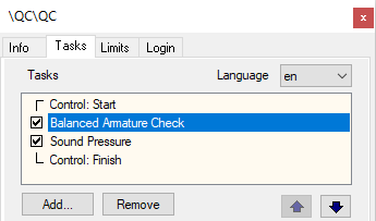
Start the QC Test; click the Add… button in the Tasks section of the property page to add a new task.
Choose the task script bac.task.klb. The default location is
%ProgramData%\Klippel\QC\Scripts\Klippel\QC\Modules
The BAC task will be added to the list of measurement tasks.
Note
Adding a new task always requires creating new reference units. You have to confirm that you want to delete all reference measurements, if limits exist in your test.
It is recommended to put the BAC at the first position in the tasks sequence to speed-up the complete test. While the BAC processes the data, the following tasks can already start measurement.
R&D System Framework#
If you are operating the BAC in the Klippel R&D System framework, you may add a QC BAC operation by using the provided operation template.
Create or open a Klippel database
Add a new operation by using the operation icon or
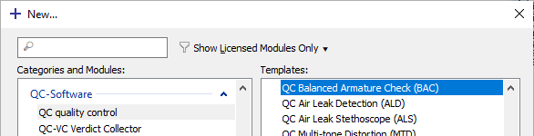
Select and , you may enter BAC in the filter input field to quickly find the template
Choose a name and click OK to create a new QC operation
Click Run
 to log in.
See also
See How to Use dB-Lab for more information.
Performing a first BAC Measurement#
This is a step-by-step guide on how to perform a first BAC measurement.
Setting up the Hardware#
Running the BAC task requires a Klippel Analyzer device (Production Analyzer or KA3) and an external or internal power amplifier (QC-Card or Amplifier-Card). It is recommended to use PA (Very High) Sensitivity version or High Sensitivity current sensor setting for KA3.
See also
Find more general information about setting up the hardware setup in Setting up Your Hardware.
Note
Using QC Stand-alone Software the BAC can also be operated with 3rd party test front-ends such as smart amplifier (Powersoft Mezzo) that provide an WDM or ASIO driver (natively or via virtual sound cards). However, optimal testing with BAC can only be ensured using a Klippel Analyzer with dedicated and highly sensitive voltage and current sensing. Please refer to QC Manual section Using Soundcards and Testing Digital Audio Devices for more information.
Your first BAC Measurement#
After creating a new BAC test, you can start with your first measurement. Choose your new QC Test and click Start to open the test.
In Engineer mode you can open the BAC task and edit the measurement parameters. See the next section for more information about these parameters.
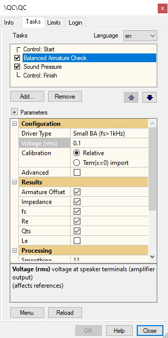
Select the correct Driver Type according to your test unit and check the voltage setting before running the BAC.
Click on the Start button to start your first measurement.
Basic Settings#
These are the basic settings that have to be considered for a successful BAC test.
Driver Type#
In this list you have to select one of the available driver types. Choose the that best fits your DUT depending on its resonance frequency (choose Small BA for \(f_{\text{s}} >\) 1 kHz and Large BA for \(f_{\text{s}} <\) 1 kHz).
Voltage#
Here the RMS voltage of the multi-tone stimulus signal is specified. It should be set high enough to drive the speaker up to the large signal range to get reliable large signal parameters.
Warning
A too high voltage can damage your transducer! Note that the peak voltage is 3 to 4 times higher than the specified RMS voltage. If calibrated (see next parameter), check peak displacement in the result table to make sure that the safe range is not exceeded.
Calibration (Relative, Tem Import)#
The BAC is based on voltage and current measurement only. A laser sensor is not required for nonlinear parameter identification. However, a mechanical calibration factor is required to get result parameters in absolute units.
In this menu you can choose to make relative measurements or to mechanically calibrate your measurements by importing the typical transduction factor of \(T_{\text{em}}(x = 0)\). If you choose relative measurements, the values of the mechanical state variables as well as the armature offset are given in percent relative to the maximum displacement during the measurement.
If you import \(T_{\text{em}}(x = 0)\), then all mechanical measures are calibrated in absolute units (e.g., displacement in µm).
Viewing BAC Results#
In this section the most important results of the BAC are explained.
Summary Window#
The Summary window shows the results measured in the BAC Task.
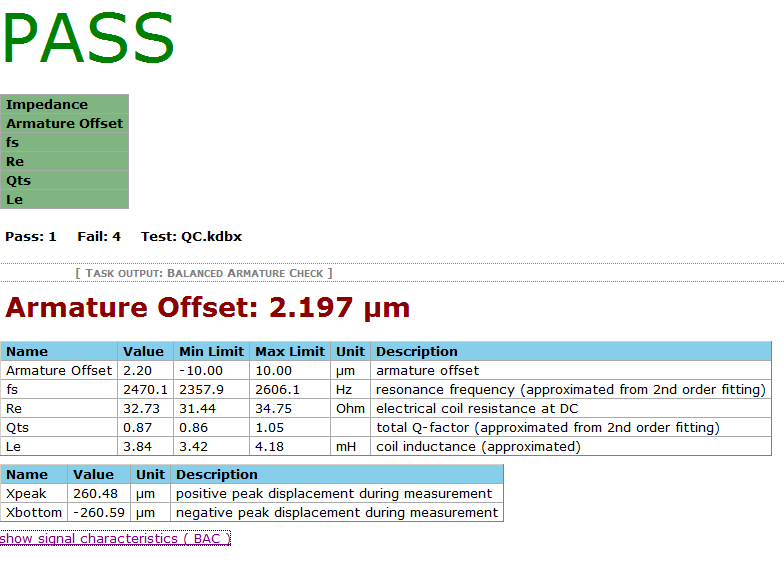
The table below gives a short explanation of the large-signal parameters measured by the BAC.
- Armature Offset
An armature offset generates 2nd -order harmonic and intermodulation distortion. \(x_{\text{offset}}\) should be as small as possible. A shift in the opposite direction of the armature offset eliminates the offset.
- \(x_{\text{peak}}\) , \(x_{\text{bottom}}\)
The \(x_{\text{peak}}\) and \(x_{\text{bottom}}\) parameters give the positive and negative peak values of the armature displacement during measurement. If no \(T_{\text{em}}\) is imported, the larger of those two parameters is set to 100 %.
Impedance#
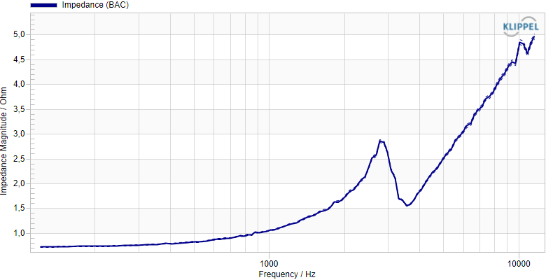
The BAC task also measures the impedance of the driver. You can find the impedance magnitude curve of the BAC in result window Impedance. If the impedance measure is activated, you can also define limits for the impedance magnitude.
Note
The impedance curve is a result of a large signal measurement. Therefore, a distorted curve is typical and expected. The curve distortion should be reproducible because it is caused by the speaker’s inherent nonlinearities.
Small Signal Parameters#
The BAC task measures the following small signal parameters:
- Voice coil resistance
- \(R_{\text{e}}\) in Ohm
- Resonance frequency
- \(f_{\text{s}}\) in Hz
- Total loss factor
- \(Q_{\text{ts}}\)
- Approximated Inductance of the LR2 Model
- \(L_{\text{e}}\) in mH
Note
The BAC works with the Wright inductance fitting, internally. Because it is unsuitable applying limits to the hardly interpretable model parameters, the simple inductance \(L_{\text{e}}\) is calculated based on the Wright parameters.
The BAC performs a 2nd order fitting of the mechanical and acoustical system. Although balanced armature receivers cannot always be described by 2nd order systems in general (because of acoustic resonances and mechanical systems with higher order), this is a very robust approach and a sufficient approximation for determining the armature offset.
Note
If BA receivers with more than one resonance peak are measured, the values \(f_{\text{s}}\) and \(Q_{\text{ts}}\) are theoretical values determined by the fitting algorithm. In this case these parameters should not be measured and no limits should be applied to them.
Measurement with Limits#
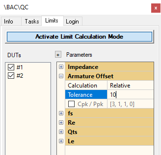
Within a BAC, task limits for the following measures can be defined:
- Armature Offset
relative, statistic, absolute, shift
- \(f_{\text{s}}\)
relative, statistic, absolute
- \(R_{\text{e}}\)
relative, statistic, absolute
- \(Q_{\text{ts}}\)
relative, statistic, absolute
- \(L_{\text{e}}\)
relative, statistic, absolute
Note
The reference value for the relative limit of Armature Offset is the \(x_{\text{max}}\) value of the reference pool, with \(x_{\text{max}} = \max (\vert x_{\text{peak}} \vert , \vert x_{\text{bottom}} \vert)\).
These limit calculation modes can be selected:
- Relative
Tolerance is the percentage the measured parameter may differ in positive or negative direction in relation to the average value of the reference units
- Statistic
Sigma is the standard deviation factor for a uniform distribution of measurement values. Statistic limit calculation is only reasonable for more than one measured reference units.
- Absolute
Gives absolute values for the lower (min) and the upper (max) limit. This value is independent of the average value of the reference units.
- Shift
The shift value is added to the average value of the reference units for the upper limit and subtracted from the average value for the lower limit.
See also
For additional information about limit calculation modes see Limit Calculation.
See also
Production capability indexes (Cpk / Pkp) can be calculated for all single-value results (for details and theory see Ppk / Cpk.
Note
The BAC task can use the calculated results from limit measurements to speed up subsequent calculations. That means the BAC calculations are considerably quicker when limits have been calculated before.
Customize your BAC Task#
This section describes how to select optimal setup parameters for the BAC task.
Find the Optimal Driver Type#
To get the best measurement results it is very important to choose the right Driver type in your BAC Task template depending on the expected resonance frequency.
You can choose your driver type according to this table:
- Small BA
\(f_{\text{s}} > 1 \; \text{kHz}\)
- Large BA
\(f_{\text{s}} < 1 \; \text{kHz}\)
As long as the Advanced checkbox is unchecked, all advanced BAC settings are chosen by default according to the selected driver type.
Setting the Stimulus Voltage#
The Voltage setting indirectly defines the peak displacement during the BAC measurement. Use a sufficiently high excitation voltage to drive the DUT in the large signal range. This is necessary to generate nonlinear distortion which is the basis for the identification of the nonlinear parameters.
Note
Increase voltage for more nonlinear distortion and more precise estimation of the armature offset. The armature offset may differ at different stimulus voltages because a DC component is generated which shifts the operating point. The level of this DC component depends on the displacement. If the output impedance of the amplifier or the resistance of the cables is not negligible, then the distorted current will also produce some distortion in the voltage measured at the terminals.
Getting Absolute Mechanical Parameters#
To measure the mechanical values in absolute units, it is required to calibrate the measurement. This can be done by inserting the transduction factor \(T_{\text{em}}(x = 0)\) under .
The transduction parameter can be measured similarly to the measurement of the force factor \(Bl(x = 0)\) of moving coil loudspeakers. These parameters are measured accurately with the LPM – Linear Parameter Measurement of the KLIPPEL R&D System or the Impedance (IMP) task (with TSX license) using a laser sensor.
Note
Calibration values have to be entered before the measurement to get absolute results; otherwise, the measurement needs to be repeated.
Advanced Parameters#
To customize the default parameters of the BAC, you can activate the advanced parameters by clicking the corresponding checkbox in the Configuration settings of the BAC task.
These parameters are set automatically for optimal performance by the parameter Driver Type.
Note
If you activate the advanced parameters, the default values are not necessarily used. You can find the recommended values for the selected driver type in the parameter comments of the property page.
For speeding up the measurements or to measure difficult DUT’s correctly, it can be useful to change some of the default settings.
- Min. Frequency
- \(f_{\text{min}}\) in Hz
The frequency \(f_{\text{min}}\) is the lowest frequency in the excitation signal. It should be roughly 10 times lower than the resonance frequency of the transducer.
- Max. Frequency
- \(f_{\text{max}}\) in Hz
The frequency \(f_{\text{max}}\) is the highest frequency in the excitation signal. It should be 3-4 times higher than the resonance frequency of the transducer.
- Resolution
The resolution parameter gives the number of excited tones per octave.
Choose \(f_{\text{min}} \leq \frac{f_{\text{s}}}{10}\) , because otherwise there are not sufficient excited frequencies below the resonance frequency. Increase Time to get a higher frequency resolution, if necessary.
Note
A higher \(f_{\text{max}}\) or a longer measurement time will increase the computing time of the BAC.
- Time
This parameter defines is the main measurement time in your BAC Task (excluding preloop).
- Preloop
This parameter specifies the additional pre-excitation time to bring the DUT in steady state conditions. It is defined as a factor relative to the stimulus length (fraction).
Note
Your total BAC Task time is the main measurement time + preloop time + computing time. Do not choose a too short preloop, it should be typically \(\geq\) 0.5 to reach steady state conditions. If you get different results depending on the polarity of the driver connection (besides inverting sign) then the preloop parameter needs to be increased.
Making the Measurement as Fast as Possible#
The total measurement time depends on the duration of the preloop (to generate steady state condition), the duration of the main measurement and calculation of the parameters. The calculation of the parameters can be performed while the next task (e.g. SPL task) is running.
Note
When Limits have been calculated for the BAC task the calculation time of the BAC will be significantly shorter. The results obtained from the reference units are used to speed-up subsequent calculations.
Main Measurement#
The default duration of the stimulus during the main measurement is 0.34 seconds for both driver types. For transducers with high resonance frequencies, Min. and Max. Frequency may be increased and the measurement time may be decreased to accelerate the BAC Task time.
Note
A longer measurement time can lead to more accurate results, but increases the calculating time.
Making the measurement shorter as the recommended values may degrade the precision of the results.
When using a shorter measurement time, the displacement is lower and the RMS voltage may be increased to reach the nonlinear mode.
Preloop#
Before the measurement starts, a pre-excitation signal is required to achieve steady-state conditions. If the transducer has significant asymmetrical nonlinear parameters, a DC component in the armature displacement can be generated which may shift the operating point. The duration of the preloop signal is always relative to the main measurement.
The default preloop time is set to 0.5, therefore the time including the preloop is \(\approx\) 1 second. Decreasing the preloop time will degrade the steady-state condition and will produce linear spectral components at low frequencies which will be interpreted as nonlinear distortion.
Note
Avoid a preloop smaller than 0.5!
Optimal Excitation Spectrum#
For the proper identification of the loudspeaker parameters a persistent excitation of the driver is necessary.
The bandwidth of the excitation spectrum is adjusted by the advanced parameters Min. Frequency (\(f_{\text{min}}\)) and Max. Frequency (\(f_{\text{max}}\)). (see start and stop in the Advanced Parameters)
The default values of our excitation spectrum are:
Driver type |
Min. Freq. (Hz) |
Max. Freq. (Hz) |
|---|---|---|
Small BA |
120 |
12000 |
Large BA |
30 |
4000 |
Note
\(f_{\text{min}}\) should be \(\frac{1}{10}\) of the resonance frequency for proper identification of \(R_{\text{e}}\) . \(f_{\text{max}}\) should be higher than 3 times \(f_{\text{s}}\) for proper identification of the inductance. Increasing the upper frequency \(f_{\text{max}}\) will significantly extend the measurement and calculation time. Increasing the bandwidth can help if you have problems to get correct results.
BAC – Reference#
Definition of Motor Parameters#
Armature Offset#
Definition#
- Armature Offset \(X_{\text{offset}}\)
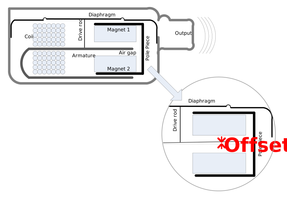
The Armature Offset is the offset of the armatures relative to its ideal rest position relative to the magnetic circuit based on the nonlinear inductance vs displacement. Negating this value gives the shift recommendation to compensate for this offset.
The definition is illustrated in the figure below.
Note
Note that the transduction parameter \(T_{\text{em}}\) defines the absolute scaling of the armature offset. The absolute armature offset may depend also on the actual excursion used in the measurement. Thus, it is recommended practice reporting the armature offset \(x_{\text{offset}}\) together with the transduction parameter \(T_{\text{em}}\) and amplitude \(X_{\text{peak}}\).
- Example
- \[X_{\text{offset}} = 40 \; \text{µm} \: (@ \: X_{\text{peak}} = 200 \; \text{µm})\]
Application to End-of-Line Testing#
An armature offset generates 2nd-order harmonic and intermodulation distortion and thus it should be as small as possible.
A permissible range defined by minimal or maximal QC limits may be applied to \(X_{\text{offset}}\) to check for a PASS / FAIL decision.
Warnings and Error Messages#
Please contact support, if any other error or warning occurs except for the following.
Specified voltage could not be realized#
The realized voltage may be less than the specified voltage due to finite output impedance of the power amplifier, cable losses or the shunt resistor in the high sensitivity channel. A warning will be generated, if the output voltage of the test is 10 % below the specified voltage.
Recommended range / recommended value#
The default BAC settings are selected according to the specified driver type. If advanced parameters are activated, then a warning is displayed when the current setting is not suitable for the measured device.
Nonlinear working range not reached#
The BAC requires measuring in the large signal range of the DUT. If the symmetrical inductance variation during the measurement did not drop to at least 70 % then a warning is displayed.
- Cause:
The measured armature offset is not reliable in this case!
- Remedy:
Increase the stimulus voltage if applicable.
Increase the stimulus time, which leads to more excited lines at low frequencies.
Poor SNR of current signal#
If the current signal is measured with an SNR lower than 5 dB then this warning is shown. In this case it is very likely, that the connection to the driver has been loose or the driver is defective.
Linear parameter estimation failed#
This error occurs if the BAC cannot determine the linear transducer parameters.
- Cause:
Linear parameter estimation failed.
- Remedy:
Check that the appropriate driver type is selected!
Return to the default values, if advanced parameters are activated.
Reduce the stimulus voltage, if applicable.
Increase the stimulus length.
High prediction failure#
The error of the linear parameter estimation is very high; the measurement results are likely to be incorrect.
- Cause:
High prediction failure
- Remedy:
Check that the appropriate driver type is selected!
Reduce the voltage if applicable.
Reduce Fmin#
The start frequency should be less than 1/10th of the resonance frequency for a correct estimation of \(R_{\text{e}}\) and for sufficient excitation below the resonance.
- Remedy:
Reduce \(f_{\text{min}}\) if applicable.
Increase the stimulus time to be able to select a lower \(f_{\text{min}}\)
Increase Fmax#
The upper frequency should be at least three times higher than the driver’s resonance frequency.
Nonlinear system identification failed#
This error occurs if the estimation of the nonlinear parameters failed.
- Cause:
Nonlinear system identification failed.
- Remedy:
Increase voltage if applicable.
Increase measurement time.
Change \(f_{\text{max}}\).
