
DCX – DC Measurement of Excursion#
DCX Add-On – Tutorial#
Overview#
The DCX Module is an add-on option for the Sound Pressure (SPL) Task and the Equalization & Alignment (EQA) task. It provides displacement-based tests.
This Add-On measures and controls the dynamically generated DC component of the voice coil in electromechanical transducers [1] . Asymmetrical loudspeaker nonlinearities generate a DC displacement which moves the coil away from the rest position. This can cause audible distortion when the voice coil hits the back-plate or produces excessive non-linear distortion. Such behavior is not intended and needs therefore to be detected and rejected by quality control. It depends on the DUT (e.g. varying material of suspension, coil positioning in the gap) and cannot be reliably detected with simple type testing in the design phase [2] .
However, an alternative approach for electrodynamic (moving coil) transducers is the direct check of nonlinear parameter variation that is provided by the MSC module (Motor and Suspension Check). The MSC module exploits the variation in the linear and non-linear parameters provided by physical models and uses this for detecting defective units. For example, the above-mentioned asymmetrical loudspeaker nonlinearities generating a DC displacement can be directly accessed [3], [4].
See the DCX Add-On – Reference for more technical background on non-linear symptoms (such as DC component) and parameters.
Envelope and DC Measurement#
This Add~on Module supports sine sweep based laser displacement measurement for production line applications. In addition to AC amplitude (envelope) testing, the dynamically generated DC component can be measured and checked against limits.
Additional verdicts are introduced for the
voice coil DC-Component vs. frequency
the peak and bottom envelope of the displacement waveform vs. frequency.
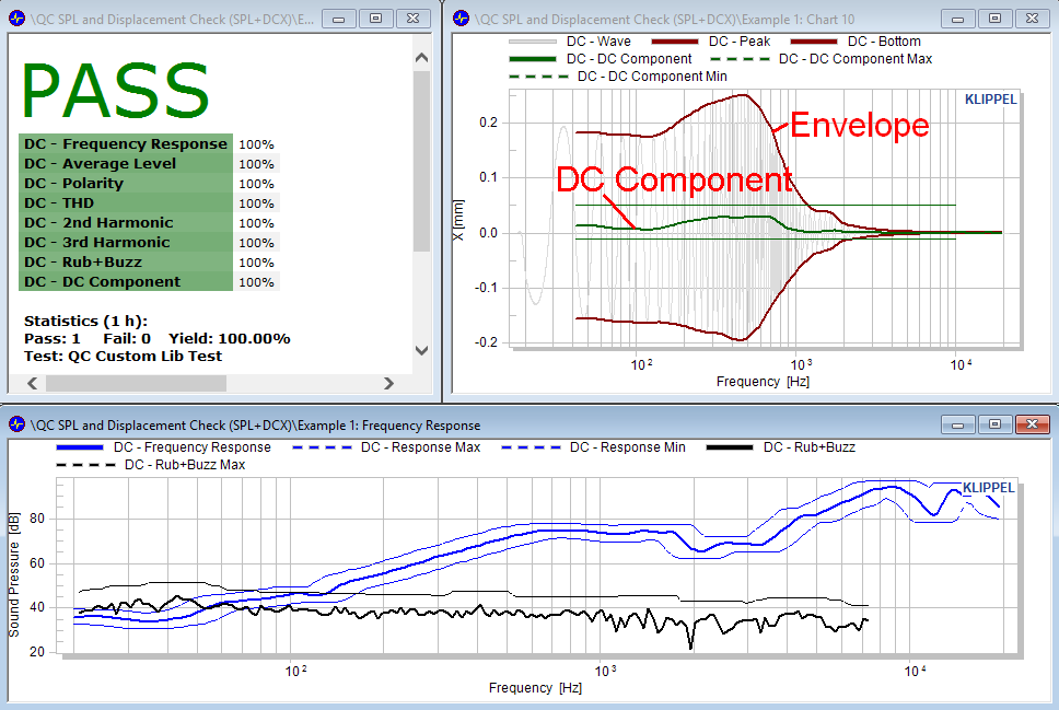
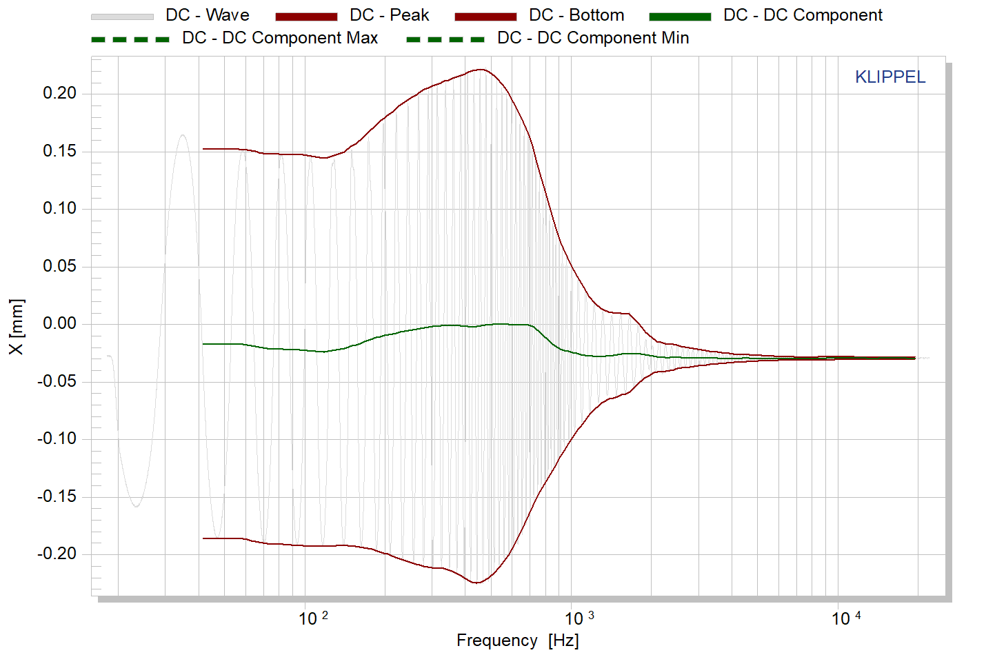
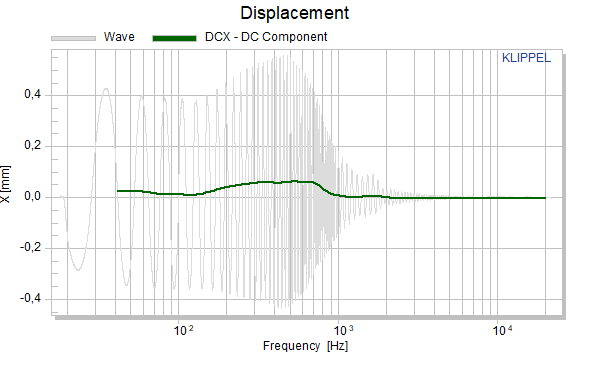
In Chart Displacement the waveform and envelope of the laser measurement and the envelope is displayed in mm. From the envelope, the DC-component is calculated:
- \(x_{\text{offset}}\)
user-defined constant or DC value at highest or lowest measured frequency for automatic compensation of varying distance between laser and DUT (to be defined depending on application).
Note
The analyzer input channel the laser sensor is connected to, must be calibrated for displacement measurement. Refer to QC User Manual for more information.
Envelope and DC Control#
In addition to testing dynamically generated DC displacement, it can be controlled by applying a DC voltage profile varying over sweep frequency (time). The stimulus parameter DC Voltage Profile available in SPL task allows defining a static or varying DC / LF voltage bias that is added to the sinusoidal sweep signal at the amplifier output.
The EQA add-on module is dedicated to controlling the amplitude and frequency response of single tone or log sweep AC responses. The DCX license unlocks displacement envelope and DC control for this task. Both, AC level profile and DC voltage profile are used to achieve a desired peak-to-peak displacement over frequency automatically by adjusting AC amplitude and removing generated DC component with a user-defined tolerance. The resulting profiles may be exported to the SPL task.
Note
In order to use DC control, KA3 either equipped with an Amplifier Card, QC Card or an external DC coupled amplifier is required.
Requirements#
QC version#
DC check available from QC5 (as a feature library, deprecated)
Envelope and DC check as an Add-On for the SPL Task available from QC6.2
DC control available from QC6
DCX license
QC Standard license or SPL-Task License
Hardware requirements#
KLIPPEL Analyzer 3 (KA3):
for DC measurement: Laser-Card
for DC Control (with EQA task):
Speaker-Card and Amplifier-Card or
XLR-Card + DC coupled amplifier or
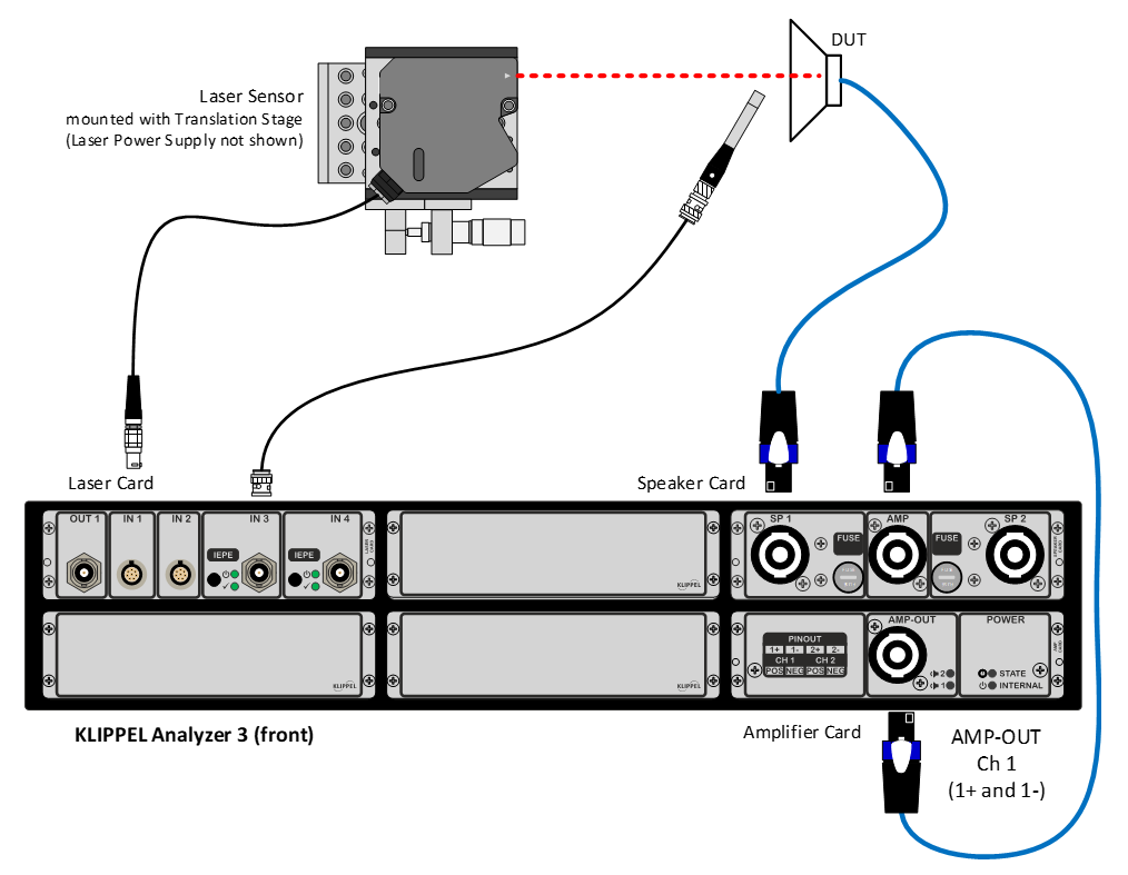
Triangulation laser sensor with Lemo connector (for KA3) or XLR output connector (for use with PA)
Enabling the Feature#
The DCX is an add~on to the SPL Task, hence no separate task needs to be inserted in the task sequence when adding to an existing test sequence that already contains the SPL task. The DCX feature is simply enabled by the installation of the DCX license.
When creating a new test,
for EoL application the use of an appropriate base template from QC-Start shall be used (e.g. Transducer / Woofer).
for R&D like operation, insert a new operation based on the operation template QC quality control / QC SPL and Displacement Check (SPL+DCX).
If the license is installed and valid, the DCX features are automatically available on the property page TASKS in section Measurements:
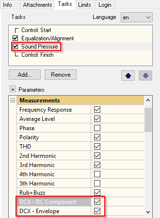
Please activate the requested measurements for your applications. See section Test Results for details on the results.
Application Examples#
In this section, several examples are introduced that show the workflow and applications of this Add-On.
Using DCX Feature for Displacement Measurement#
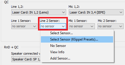
Select laser sensor to apply correct calibration factor via :
Also, customized laser calibration can be used. See QC User Manual section Microphone & Sensor Calibration for more information.
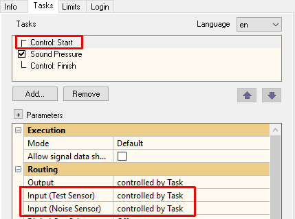
On property page TASKS for Control Task set the Input routings to Controlled by Task:
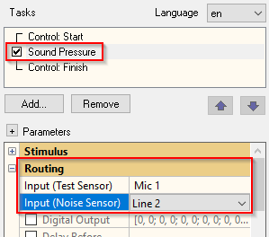
On property page TASKS for Sound Pressure (SPL Task) set the Input routing to any microphone input and the Input Noise Sensor routing (which is (mis-)used in this particular case for the laser measurement) to preferably any line input of the Laser-Card (with LEMO inputs dedicated to laser sensors).
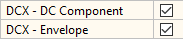
In Section Measurements the enable the check boxes:
Run a measurement. In chart Displacement the displacement waveform with the derived DC component and envelope is shown:
Limits can be defined on Property Page LIMITS. Activate limit mode and select the section DC-Component:
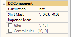
Several limit modes are available, refer to the QC User Manual for details.
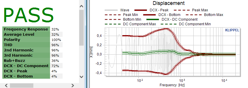
Once limits are defined, the additional verdict DC-X and Peak-X, Bottom-X are added to the verdict list and measured results with limits are displayed in chart Displacement:
- Advanced Comments
The laser must be connected to the input selected for Noise Monitoring.
At login time and when closing the Configure Hardware Dialog, the actual DC value present at the laser output is used as a “reference” and subtracted from any following measurement. It is good practice to set the laser output to 0 V (rest position in most cases, depends on laser sensor).
Nonlinear characteristics of transducer can be checked very efficiently using the Motor and Suspension (MSC) check. Please contct support for more information. MSC measurements and DC-Displacement measurements are both evaluating non-linear symptoms. MSC tests do not need displacement sensors but provide relevant non-linear characteristics based on (much more robust) current and voltage measurement dispensing also with the need of optical “visibility” of moving cone (e.g. side fire micro speakers cannot be checked with laser) [3], [4].
Using the DCX Feature for Displacement Control#
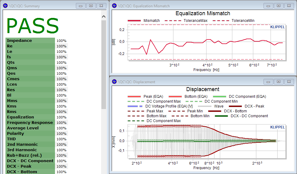
In addition to testing the displacement waveform envelope and DC component, those excursion properties can also be controlled by the EQA task with DCX Add-On automatically to match user defined properties (such as define peak displacement or envelope and/or also compensating DC components ensuring a symmetric waveform). Both, AC and DC voltage profiles are calculated by the EQA task. The resulting equalization profiles can be exported on-line to the SPL task in order to test under controlled displacement conditions. This displacement-controlled operation of the DUT can be used to check distortion (e.g. Rub&Buzz) for a defined and critical excursion pattern.
For more general information about the EQA task and settings+data transfer, refer to EQA User Manual and QC User Manual section Settings Import.
Add an EQA task to the test sequence using the Add.. button () and move it before the SPL task in the test sequence
In EQA properties section Configuration set Mode – Automatic, Adjust – Envelope, Peak or Bottom, Measured Quantity – Displacement according to your application
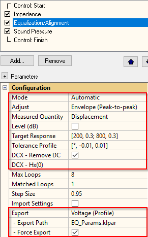
Also define the Target Response and Tolerance Profile in mm, either as a frequency dependent profile or as constant numbers.
Activate DCX - Remove DC, if the dynamically generated DC displacement shall be removed (compensated) using a DC Voltage Profile. Enter the transfer factor between voltage and displacement for low frequencies, if known, otherwise leave it empty.
Note
Both, AC control (envelope only) or DC control (DC-component only) or a combination can be applied.
Activate Export to transfer the results to the Sound Pressure task
Set the Stimulus properties according to the requirements. Also define the maximal AC and DC voltage limits that may be applied during equalization process
In Processing properties, define how the DC input signal is handled by selecting DC - Offset Compensation. Normally the zero-displacement reference point is defined at upper frequency limit, where displacement is low (mode DC at high frequencies).
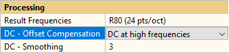
In category Display, you may set whether the result curves for envelope and DC shall be displayed after the equalization (or only the test result of the main measurement of the Sound pressure task, instead).
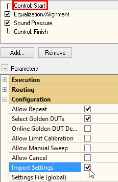
Switch to Control:Start properties and activate settings import as shown below to activate import parameter section in Sound Pressure task
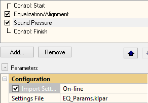
Switch to Sound Pressure task properties and activate Import Settings and enter the name of the settings file exported by EQA task.
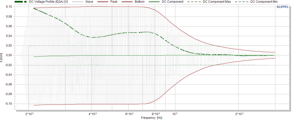
After running the test, an additional curve is displayed in Chart Displacement representing the applied DC voltage profile in V that has been determined by the EQA and applied to remove dynamic DC displacement according to the specified tolerances.
Record Reference DUT’s and check samples. Due to the complexity of this control method you may contact support for dedicated help and support.
DCX Add-On – Reference#
In this chapter all results and parameters of the Property Pages TASKS and LIMITS are described.
Test Results#
DC Component of coil displacement#
Due to non-linear properties of an electromechanical transducer the voice coil may produce a DC component even when excited by a pure AC signal.
In Chart Displacement the waveform and envelope of the laser measurement and the envelope is displayed in mm. From the envelope, the DC-component is calculated:
- \(x_{\text{offset}}\)
user-defined constant or DC value at highest or lowest measured frequency for automatic compensation of varying distance between laser and DUT (to be defined depending on application).
Note
The analyzer input channel the laser sensor is connected to, must be calibrated for displacement measurement. Refer to QC User Manual for more information.
Displacement Envelope#
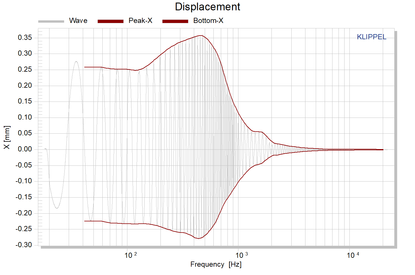
The envelope is derived from the waveform using a simple peak and bottom value detection. Be careful with extensive smoothing since this will attenuate peaks and dips in the envelope.
Add-On Properties#
Category Stimulus#
- DC Voltage Profile (SPL, EQA)
Format: Two-column matrix
[Instantaneous Sweep Frequency in Hz, Voltage in V]This parameter allows defining a variable DC (or better: very low frequency) voltage over sweep frequency that is added to the AC stimulus signal.
- Max DC Voltage (EQA)
Maximal allowed DC voltage at speaker terminals (or line out) that may be applied during automatic removal of DC displacement. When using internal Amplifier-Card, max DC voltage is 20 V.
Category Measurements#
- DCX – DC Component (SPL)
This parameter in section Measurements enables the test of the dynamically generated DC displacement of excursion versus frequency against limits. It is disabled by default. If this parameter is enabled, the measured excursion and the envelope is displayed in result chart 10.
- DCX - Envelope (SPL)
This bool parameter enables the test of the peak and bottom displacement of excursion versus frequency (envelope) against individual limits. Separate limits are available for peak and bottom excursion. It is disabled by default. If this parameter is enabled, the measured excursion and the envelope is displayed in result window Displacement.
Category Processing#
- DC/DCX - Offset Compensation (EQA/SPL)
DC at high frequencies: compensates automatically any offset measured at highest valid frequency. This point is defined to be 0 mm. This option can be used to compensate distance variation between laser sensor and DUT. It is recommended for down sweep direction.;
DC at low frequencies: compensates automatically any offset measured at lowest valid frequency. This point is defined to be 0 mm. This option can be used to compensate distance variation between laser sensor and DUT. It is recommended for up sweep direction.;
specified value: Specify any numeric distance as an offset. This value is added to the actually measured laser signal.;
none: does not alter measured displacement.
This parameter defines the displacement offset.
Note
This is not a user defined rest position! See DC/DCX - Offset Value (EQA/SPL) below.
- DC/DCX - Offset Value (EQA/SPL)
This numeric parameter defines the offset applied to measured displacement if DCX – Offset Compensation is set to specified value.
Note
In this case the distance between DUT and laser is crucial and any variation will influence the results.
- DC/DCX – Smoothing (EQA/SPL)
This numeric parameter defines the smoothing applied to the DC curve and the envelope curve (Peak, Bottom). The value is the inverted part of an octave. For example, DCX - Smoothing = 1 applies a smoothing of one octave. DCX - Smoothing = [] disables any smoothing. The DCX -Smoothing value must be positive and non-zero.
Category Configuration#
- DCX - Remove DC (EQA)
Activates control of (dynamic) DC component in displacement waveform. If activated, any time-variant bias of AC signal is removed using DC Voltage Profile. Follows DC definition set by parameter DC Offset Mode.
Note
DC removal is possible only if signal chain is DC coupled entirely.
- DCX - Hx(0) (EQA)
optional parameter if Remove DC activated.
Specifies typical transfer factor (\(H_{x} = \frac{X}{U}\) @ DC in mm/V) for DC control. If empty, this parameter is estimated from AC response (may degrade control and timing performance)
Note
Use a greater value to prevent over-compensation. DC control is only possible if signal chain is entirely DC coupled (e.g. KA3 with QC or Amp Card).
Limits#
Limits can be configured based on parameters. They are accessible in the Limit Calculation Mode.
There are no DCX-related measures nor limits available for the EQA task. Limits are available for SPL Task only.
Select the measure and expand all items if it is collapsed. For details on limit calculation methods, import of reference DUT’s and control rules, please see the QC User Manual section Test Configuration / Limit Calculation.
References#
The following literature may be useful for better understanding of the DC component of coil excursion:
