
I/O & Prompt#
IO & Prompt - Tutorial#
Overview#
The IO & Prompt is an auxiliary task providing multiple ways of interaction with the operator or the hard- and software environment. It does not provide a generator or analyzer function.
Actions are performed according to specific conditions. Possible conditions are:
Digital input
All tests passed
Last test passed
Noise corrupted
Always
Actions are performed either if the condition is met or if the condition is NOT met.
The user interface has a simple IF-THEN-ELSE structure. If one of the IF-conditions is met then the THEN-actions are performed otherwise the ELSE-actions are performed.
Possible actions are:
Message box
Run batch file
Wait for digital input
Digital output
Cancel test
Logout
Wait
Inserting the IO task#
To add the IO & Prompt Task to your task sequence:
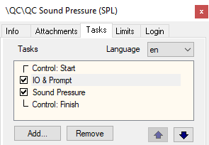
Select a QC test and login as Engineer
Open Property Page Tasks
Use the Add button to include the IO & Prompt Task in the test sequence.
The default locations is:
%ProgramData%\Klippel\QC\Scripts\Klippel\QC\Modules\io.task
Note
When inserting a new task, any reference data will be deleted – please backup the test database.
Use the up/down arrow buttons to set the correct position in the task sequence.
Application Examples#
In this section, several applications are introduced that show the application of this task.
User Prompt#
The first example is a user dialog that is shown in every test run. This can be used to instruct the operator about the test procedure.
Condition#
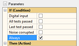
Please select Always as condition.
Action
Select Message box as action.

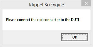
Every time the task sequence is performed a dialog box is shown.
Note
Line breaks can be inserted with \n, tab stops with \t. The sequence \\ is needed for a single \ (backslash).
User Prompt for Manual Verdict#
The second example is also based on a user dialog but in this case, it is not only used to display instructions but also for entering a test verdict that will show in the PASS/FAIL verdict list. This can be used to include the result of manual test steps in the QC test sequence such as a visual inspection or a manual measurement.
Condition#
Please select Always as condition.
Action#
Select Messagebox as action and enter instructions for the operator. Enable Verdict check in order to activate additional buttons in the message box. The optional verdict label allows customizing the displayed label in the verdict list.
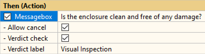
Every time the task sequence is performed, a dialog box is shown.
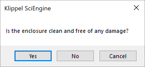
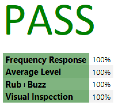
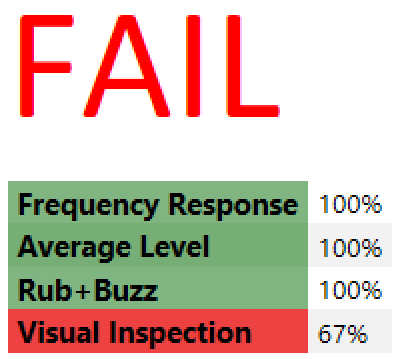
Clicking Yes will add a Visual inspection - PASS verdict, while No will result in a FAIL. If activated, Cancel can be used to abort the sequence.
Wait for Digital Input#
In this example the test shall be interrupted until a certain IO-pin of the Digital IO port of the KLIPPEL Analyzer is set.
Condition#
Please select Digital input as condition and enter the matrix for the digital input. Let’s assume, that you only want to check pin 10. If the pin has the value 1 the defined action should be performed.
DigiInCond = [
1];
This is a simple example, for more information and more complex examples about defining GPIO matrices, refer to Defining Digital I/O (GPIO) Matrices.
Action#
As an action we can use the message box, too or even disable all actions to just wait for the input to be set.
Conditional Wait for Digital Input#
The above example can be extended to be conditional. A typical application is to wait for a mechanical feeder in case of a failed DUT.
Condition#
Select All tests passed here.
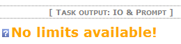
This setup requires limits. If no limits are defined, a warning is shown in the Summary window:
For information about the other conditions, please refer to Section “If (Condition)”
Action#
In this example, the failed DUTs require an action. In other words, an action needs to be triggered if the condition All tests passed is NOT met. Thus, the Else (Negated Action) section is used.
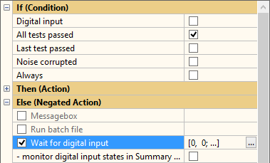
Select Wait for digital input as action. Let’s presume you want to wait until GPIO input 1 (pin 10) has the value 1:
Else_WaitDigiIn = [
1];
The IO & Prompt Task will pause until the expected value of digital input pin is set. You may monitor the states of the digital inputs by activating option - monitor digital input states in Summary window.

You can define an additional message box when the awaited digital input occurred by selecting Message box after digital input.
This is a simple example, for more information and more complex examples about defining GPIO matrices, refer to Defining Digital I/O (GPIO) Matrices.
Set Digital Output#
In this example, a digital output pattern is set to control e.g. an automated line interface.
Condition#
Select e.g. Always here.
For information about the other conditions, please refer to: Section “If (Condition)”
Action#
Select Digital output as action. Let’s assume you want to set output pin 24 (User Out 1) to high level and pin 17 (User Out 4) to low level (red text is comment). If Mask is set to 0, the bit is neither set nor reset, it is ignored.
Action_DigiOut = [
1 1   Pin 24 (1): Value = 1 \| Mask = 1 (bit set)
0 0   Pin 11 (2):              Mask = 0 (bit ignored)
0 0   Pin 5  (3):              Mask = 0 (bit ignored)
0 1]; Pin 17 (4): Value = 0 \| Mask = 1 (bit reset)
This is a simple example, for more information and more complex examples about defining GPIO matrices, refer to Defining Digital I/O (GPIO) Matrices.
Delay / Wait#
After a test, a defined time may be needed to wait for the next test (e.g. positioning of DUT, open or close test chamber etc).
Condition#
Select e.g. Always here.
For information about the other conditions, please refer to Section “If (Condition)”.
Action#
Select Wait as action and enter the desired wait time in milliseconds.
DUT Protection and Verification#
If the QC System is used to measure different types of loudspeakers with different specific setups it may be required to check that the measurement setup and the connected DUT match.
The IO & Prompt Task in combination with a measurement task can be used to protect the DUT from potentially harmful signals (e.g. caused by high voltages or excitation of the wrong frequency range). Another application is to check certain properties of a DUT before performing critical (dangerous) tests. For example, using the Impedance task, resonance frequency and \(R_{\text{e}}\) may be tested before running high level SPL tests.
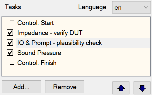
In this example an Impedance task (postfix: “verify DUT”) is used to measure the DUT at a low voltage. The measured values \(R_{\text{e}}\) , \(f_{\text{s}}\) and \(Q_{\text{ts}}\) are checked against very wide limits. This check is performed only to prove that the DUT has roughly the expected parameters of the type of loudspeaker the test was set up for.
In the second task IO & Prompt - plausibility check the QC System checks whether the DUT has passed the Impedance task.
Condition#
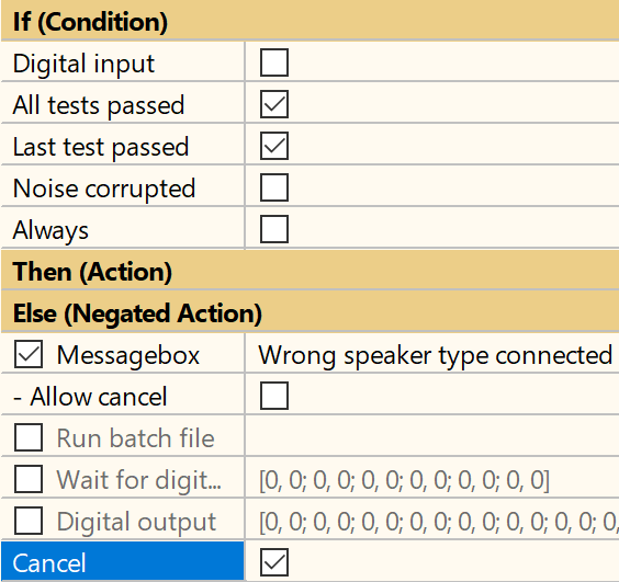
Select Last test passed. This will check the PASS/FAIL results of the preceding Impedance task.
For information about the other conditions, please refer to Section “If (Condition)”.
Action#
Select Messagebox and Cancel as action in the Else (Negated Action) section and enter the message to be prompted.
Conclusion#
If the measurement is run with a DUT that does not meet the rough specifications, it will be rejected. The test is aborted and a message is prompted. If the DUT is appropriate for the test sequence the, subsequent tasks will be executed. Those tasks can now safely supply more power to the DUT without the risk of destroying it.
Temperature and Humidity Check#
If an audio system check shall be done under specified environmental conditions, enable the Temperature / Humidity Check:
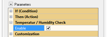
Activate Limit Calculation Mode and define the limits of the allowed operation range:
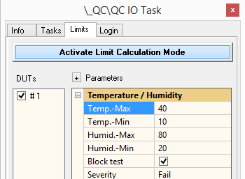
In this example temperature is allowed to be between 10 °C and 40 °C.
Note
The input of temperature in °F is not supported. Use any conversion tool if needed.
Humidity must be within 20 % and 80 % relative humidity.
The Block Test option suspends any test when no temperature sensor is connected.
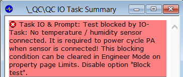
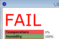
If the actual environmental conditions are out of tolerance, the test fails according to the Severity parameter setting.
IO & Prompt - Reference#
Section “If (Condition)”#
The conditions are linked with an OR-operation.
Digital input#
If the digital input equals the defined input matrix, the condition is fulfilled. The user has to define an input matrix. This condition does not require limits. Please refer to Defining Digital I/O (GPIO) Matrices.
All tests passed#
This condition requires available limits. If the verdicts for all preceding tests (before the IO & Prompt Task) are PASS, the condition is fulfilled.
Last test passed#
If the verdicts for the last preceding task before the IO & Prompt Task are PASS, the condition is met. This condition requires available limits.
Noise corrupted#
The condition is met, if any of the preceding tests was corrupted by ambient noise. This condition requires available limits.
Note
Ambient Noise Detection must be available and activated to apply this condition.
Always#
The condition is always set, the selected actions are performed every time. It does not require limits.
Section “Then (Action)”#
Relates to the sections Then (Action) and Else (Negated Action).
The actions are performed in the given order:
Message box
Run batch file
Wait for digital input
Digital output
Cancel (disables the following action)
Logout
Wait
Message box#
If the condition is fulfilled, a message box is shown. The text content can handle strings of more than 300 characters.
Note
Line breaks can be inserted with \n, tab stops with \t. The sequence \\ is needed for a single \ (backslash).
Allow cancel#
Activating this option adds a cancel button to the message box allowing the operator to abort the test.
Verdict check#
Activating this option adds additional Yes and No button to the message box allowing the operator to enter a manual PASS or FAIL verdict.
Verdict label#
In case Verdict check is activated, a custom label can be entered here that will be shown in the PASS/FAIL list in Summary window. If left empty, a default verdict label is used.
Run batch file#
A selected batch file is executed. This action can be used to control any external program or to start processes that need to be performed before, after, between or during a measurement task.
Further information on batch files can be found here .
Wait for completion#
Select - wait for completion if the test execution is supposed to wait until the batch file execution finishes. If this option is not selected, the QC System will proceed while the batch file is executed.
Run silent#
If this option is enabled, the command window will be hidden during execution.
Environment variables#
To include further information on the current test, the IO Task creates environment variables that will be available during batch execution. These variables represent a selection of internal system variables:
Cfg_DatabasePathfull path of currently used database (database in current test folder)
Cfg_DutStartTime- Format: see SciLab function
getDate()Date Time of start.
Cfg_LimitCalcModetrue if limit calculation mode is activated on property page Limits
Cfg_LimitCalibModetrue if calibration of limits has been started
Cfg_LimitsAvailtrue if all limits of all tasks required to run the operation are calculated. It is also true, if no limit is required.
Cfg_LoginMode- Values: OPERATOR, ENGINEER, PROGRAMMER
login mode
Cfg_MonitorIDName of IO Monitor client (see Remote Control).
Cfg_PCNameProvides Windows name of computer
Cfg_SerialNumberserial number of current DUT
Cfg_Speakercurrently used speaker channel
Cfg_UserNamecurrent user name
Ctrl_ErrorGeneralglobal error message If non-empty the measurement will be blocked and the error message is shown in the Summary window.
Ctrl_Repeattrue, if the test (all tasks) is going to be repeated
Ctrl_SaveDataCarries the full file name for data logging (. kdbx file).
Ctrl_LogFolderAbsolute path to the folder used for data logging
Cfg_ExecutionModesession-wide execution mode This variable is mainly dedicated to external synchronization modes.
Results_Passstring with all passed test results (tab separated)
Results_Failstring with all failed test results (tab separated)
Results_Warningstring with all warning test results (tab separated)
Results_Voidstring with all void test results (tab separated)
Results_Noisestring with all noise test results (tab separated)
Results_Invalidstring with all invalid test results (tab separated)
Meas_Trigger- Values: start, repeat
Measurement trigger.
- Example code
echo DUT serial number: %Cfg_SerialNumber%
Wait for digital input#
This action waits until the digital input equals the defined input matrix. Please refer to Defining Digital I/O (GPIO) Matrices.
An additional, optional message box can be defined. This message box is shown after the expected digital input values are correct. Using this second message box, the operator can be instructed to activate an input and if done, how to proceed using one single IO task.
Digital output#
This action sets the digital output e.g. for controlling an automated environment or multiplexers.
Please refer to Defining Digital I/O (GPIO) Matrices.
Note
When used to control KLIPPEL Multiplexer, please refer to the specification A8 Multiplexer.
Cancel#
This action cancels the current test run. This can be used if a certain condition is not fulfilled, together with an appropriate message.
Logout#
This action logs out the user from the current test run. No PASS/FAIL verdict will be calculated or shown. This can be used in case of any emergency or if any further processing of the test sequence shall be blocked. An appropriate message shall inform the user.
Wait#
This action makes the IO & Prompt Task wait for the defined time in ms.
Checking Validity of Temperature and Humidity#
In section Temperature and Humidity Check a user specified range of environmental conditions can be ensured. On Property Page Tasks enable the feature and adjust the allowed working range on Property Page Limits.
Note
Note that for this option the accessory Temperature + Humidity Sensor (Item No. 2800-001 or 2800-011) must be used.
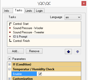
Limits can be defined as either upper or lower limit or as a range. Simply leave the input field empty, if not required. The Severity can be defined as Warning or FAIL.
Furthermore, test execution can be blocked if no sensor is connected in order to avoid testing without recorded environmental data.
Defining Digital I/O (GPIO) Matrices#
Pins of digital input (Production Analyzer):
Name |
User Input Index |
Pin at IO Connector |
|---|---|---|
User In 1 (opto) |
1 |
10 |
User In 2 (opto) |
2 |
22 |
User In 3 (opto) |
3 |
21 |
User In 4 (opto) |
4 |
8 |
Start (User In 5) |
5 |
7 |
Sensor / User In6 |
6 |
19 |
Pins of digital output (Production Analyzer):
Name |
User Output Index |
Pin at IO Connector |
|---|---|---|
Result (User Out 1) |
1 |
24 |
Sensor / User Out 2 |
2 |
11 |
User Out 3 |
3 |
5 |
User Out 4 |
4 |
17 |
User Out 5 |
5 |
4 |
User Out 6 |
6 |
16 |
User Out 7 |
7 |
3 |
User Out 8 |
8 |
15 |
User Out 9 |
9 |
2 |
Note
If the legacy temperature sensor (item no. 2800-001) (“User In6”, or “User Out 2”) is connected at power up, this output is used exclusively for the sensor communication.
For more information about the Digital I/O connector (GPIO), refer to I/O Connector.
Note
The values of the GPIO are also available in the QC Automation API.
The optional 2nd column in the matrix dialog is reserved for a mask. If a mask is defined, only the pins with a mask-value 1 are checked (digital input) or set (digital output). Pins with a mask-value 0 are not affected.
Unspecified pins (see Example 2 and Example 3) are passive as well.
Example 1#
Setting an input matrix for User Input 1 = 1, all other 0
DigiInCond=[
1
0
0
0
0
0];
Example 2#
Setting an input matrix for User Input 1 = 1, all other pins passive (keep states)
DigiInCond=[
1 1
0 0
0 0
0 0
0 0
0 0];
or
DigiInCond=[
1 1];
or
DigiInCond=[
1];
Example 3#
Defining an output:
User Out 1 = 0, User Out 3 = 1, User Out 5 = 1, User Out 6 = 0, others = passive
Action_DigiOut=[
0 1
0 0
1 1
0 0
1 1
0 1
0 0
0 0
0 0]; //or: 1 0
or:
Action_DigiOut=[
0 1
0 0 //or: 1 0
1 1
0 0 //or: 1 0
1 1
0 1];
Settings & Limit Import#
All task properties may be imported from an external parameter file during login.
The following section lists the internal IDs of the parameters and the corresponding text labels (English version) as shown in the user interface. Only use the IDs for import.
Conditions#
- Digital input
- Type: boolID:
Cond_DigiIn - Digital input
- Type: string matrixID:
DigiInCond - All tests passed
- Type: boolID:
Cond_PassAll - Last test passed
- Type: boolID:
Cond_PassLast - Noise corrupted
- Type: boolID:
Cond_Noise - Always
- Type: boolID:
Cond_Always
If Branch#
- Messagebox
- Type: stringID:
Action_MessageTxt - Allow cancel
- Type: boolID:
Action_MsgBCancel - Verdict Check
- Type: boolID:
Action_MsgBVerd - Verdict label
- Type: stringID:
Action_MsgBVdLab - Run batch file
- Type: stringID:
Action_RunBatch - wait for completion
- Type: boolID:
Action_RunBatWait - run silent
- Type: boolID:
Action_RunBatHide - Wait for digital input
- Type: numerical matrixID:
Action_WaitDigiIn - monitor digital input states in Summary Chart
- Type: boolID:
Action_ShowDigiIn - Message box after digital input
- Type: stringID:
MessageTxtDigiIn - Allow cancel
- Type: boolID:
A_TxtDigiInCancel - Digital output
- Type: numerical matrixID:
Action_DigiOut - Logout
- Type: boolID:
Action_Logout - Cancel
- Type: boolID:
Action_Cancel - Wait
- Type: numerical valueID:
Action_WaitTime
Else Branch#
- Messagebox
- Type: stringID:
Else_MessageTxt - Allow cancel
- Type: boolID:
Else_MsgBCancel - Verdict Check
- Type: boolID:
Else_MsgBVerd - Verdict label
- Type: stringID:
Else_MsgBVdLab - Run batch file
- Type: stringID:
Else_RunBatch - wait for completion
- Type: boolID:
Else_RunBatWait - run silent
- Type: boolID:
Else_RunBatHide - Wait for digital input
- Type: numerical matrixID:
Else_WaitDigiIn - monitor digital input states in Summary Chart
- Type: boolID:
Else_ShowDigiIn - Message box after digital input
- Type: stringID:
ElseMessageTxtDigiIn - Allow cancel
- Type: boolID:
E_TxtDigiInCancel - Digital output
- Type: numerical matrixID:
Else_DigiOut - Logout
- Type: boolID:
Else_Logout - Cancel
- Type: boolID:
Else_Cancel - Wait
- Type: numerical valueID:
Else_WaitTime
Others#
- Temperatur / Humidity Check - Enable
- Type: boolID:
THSensorOn - Temp. – Max
- Type: numerical valueID:
tempMaxUI - Temp. – Min
- Type: numerical valueID:
tempMinUI - Humid. – Max
- Type: numerical valueID:
humidMaxUI - Humid. – Min
- Type: numerical valueID:
humidMinUI - Block test
- Type: boolID:
blockIfNoSensor - Severity
- Type: stringID:
blockIfNoSensorOptions:Warning:
‘warn’Fail:
‘fail’
- Customizations
- Type: boolID:
clibOn - (Custom) Parameters
- Type: String matrixID:
clibParam - (Custom) Setup
- Type: String matrixID:
clibSetup
Note
For general information on importing task parameters, see section Settings Import in QC User Manual.
Troubleshooting#
Please contact KLIPPEL support, if any other error or warning occurs except for the following.
Error Messages#
“all elements must be 0 or 1”#
- Solution:
The I/O matrices must not have entries differently from 0 or 1.
“max 6 rows and 2 cols expected”#
- Solution:
Input matrices must not exceed the size of 6x2. The rows represent the pins 10, 22, 21, 8, 7, 19. Column 1 represents the value, column 2 represents the mask: 0 is passive, 1 is active.
“max 9 rows and 2 cols expected”#
- Solution:
Output matrices must not exceed the size of 9x2. The rows represent the pins 24, 11, 5, 17, 4, 16, 3, 15, 2. Column 1 represents the value, column 2 represents the mask: 0 is passive, 1 is active.
“out of range”#
- Solution:
The valid range for the Time to wait must be positive. The time is given in ms.
Warnings#
No limits available#
- Cause:
The user has chosen a condition, which implies available limits, but no limits are available.
- Solution:
Define limits in Limit Calculation Mode.
