
EXD – External Devices#
EXD - Tutorial#
The External Devices (EXD) Tutorial provides guidelines on how to get started with this QC task.
Overview#
The External Devices (EXD) is an add-on to the Klippel Analyzer System for the QC Software framework. This versatile, step-based QC task provides interfaces for communication with 3rd party devices and applications. A wide range of measurement equipment can be controlled and queried via GPIB IEEE 488.1 and IEEE 488.2 standard to include external measurement data in the QC System.
In addition to GPIB communication, the EXD provides functionality for Bluetooth® and sound device handling or accessing the KLIPPEL Analyzer’s Digital I/O port, creating message boxes for the operator, command line execution and text file-based data import. It also provides different test signal generators for tests with 3rd party instruments.
All external data acquired by the EXD is handled like normal QC test results including limit calculation, process control and statistics. With EXD Pro license, custom step sequences can be generated using the full feature scope of the EXD empowering the user to create complex test and control sequences.
For common straight-forward applications like Bluetooth audio control, the EXD also provides a preset mode for minimum effort and quick setup. Some presets can be operated with dedicated licenses (e.g. EXD Bluetooth) without requiring the full EXD Pro license. Also refer to Application Note 76 Quality Control of Wireless Audio Devices for more information.
What is the Goal of This Tutorial?#
This tutorial makes you familiar with two typical applications of the EXD module: GPIB communication and Bluetooth device handling. It is divided into the following steps:
Setting up the Hardware#
This section addresses hardware setup related to GPIB instrumentation or Bluetooth interfacing.
Hardware Framework#
Depending on the particular application, the EXD may be operated together with various hardware configurations using the KLIPPEL QC Production Analyzer (PA), the KLIPPEL Analyzer 3 (KA3) or 3rd party audio devices. Find general information in QC User Manual section Connecting the System.
GPIB Application#
The following information is related to setting up the GPIB controller as well as the connected GPIB enabled devices.
Setting Up the GPIB-USB Controller#
To establish GPIB communication, a GPIB controller interface for the PC is required. The EXD task supports the Prologix GPIB-USB controller as a versatile and cost effective virtual serial port device (see S31 QC – External Devices specification for more information).
Connect the controller to your USB port. If the hardware does not install automatically, install the USB driver available in Optional Features of QC Install Guide accessible via or from the manufacturer website.
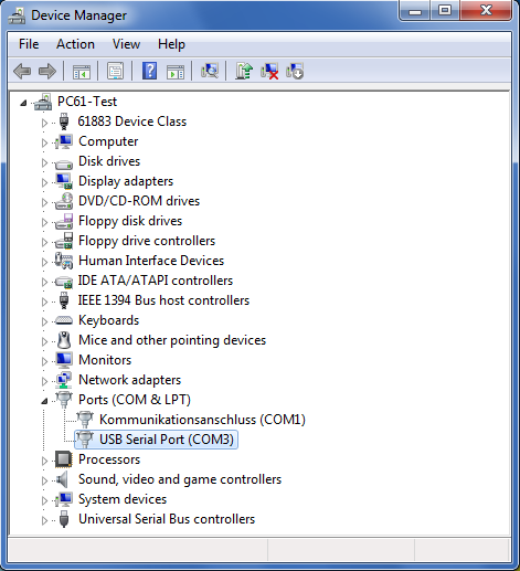
The controller should now be available as a USB Serial Port (COM <number>) in the Device Manager of the System dialog in the Windows Control Panel as shown in the example below.
Note
The COM port number should be smaller than 20 for automatic initialization.
Setting Up the GPIB Device#
After installing the GPIB controller it can be connected to your GPIB devices directly or via a GPIB cable if multiple devices are used. The minimal setup using an external DMM (Digital Multimeter) is shown in the schematic below.
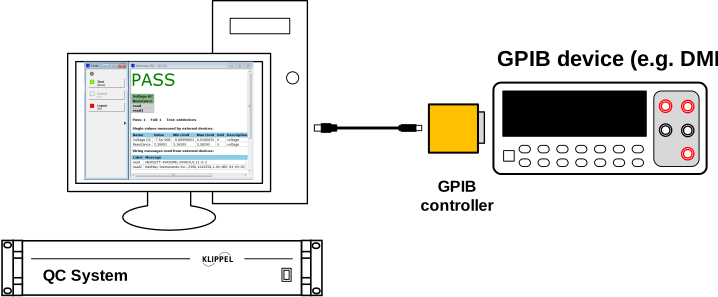
Now the device has to be set up for GPIB communication with a unique bus address. For information about setting up your specific device for remote control please refer to the operation or programming manual provided by the manufacturer.
Bluetooth Audio Application#
The EXD supports two different ways to interface with Bluetooth audio devices for automated pairing and service control.
MegaSig U9xx Bluetooth Interface#
Test Setup#
The recommended way for testing Bluetooth enabled audio devices with KLIPPEL QC is based on the USB controlled MegaSig U980 Bluetooth interface. Since the U980 provides analog, stereo inputs (to DUT speaker) and one mono output (from DUT mic), it is connected directly to the line in- and outputs of the KLIPPEL Analyzer.
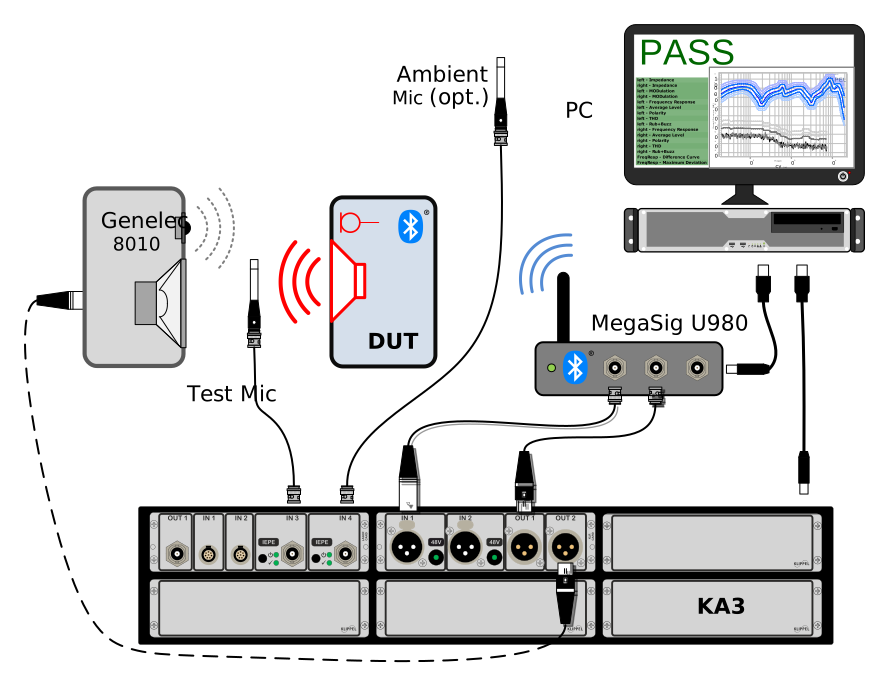
Additionally, the device is connected to the host PC via USB providing the control interface used by the EXD. The shown example also includes an active speaker for testing the DUT ’s microphone via Hands-Free Profile.
Setting Up the Bluetooth Interface#
The MegaSig U9xx Bluetooth interfaces provide a USB control interface for software—controlled connection and configuration of audio devices with Bluetooth wireless technology. Since the control interface is implemented as a virtual serial port, a COM port number will be assigned after connecting the device via USB and installing the driver.
If the hardware does not install automatically, install the USB driver available in Optional Features of QC Install Guide accessible via . The drivers and additional software for manual operation is also available from the manufacturer website.
The device should now be listed as a USB serial port (COM <number>) in the Windows Device Manager.

Note
You may change the port number manually, it should be below 20 and possibly first in order for efficient automatic initialization. Alternatively, you can enter the corresponding port number directly in EXD which is optimal for best timing during login.
Windows Bluetooth Radio#
An alternative way to interface with Bluetooth audio devices is the Windows Bluetooth stack. In order to enable and use Windows Bluetooth Radio together with the EXD, connect a Bluetooth radio USB dongle to the PC or use the internal radio, alternatively. A list of recommended dongles can be found in specification A6 Accessories.
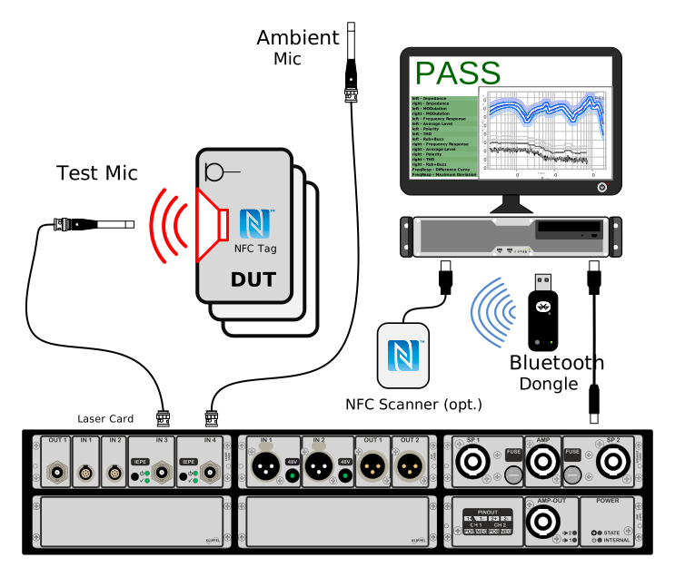
The schematic above shows an example setup for a Bluetooth speaker test using a Bluetooth dongle as playback device and the KA3 as capture device for the sound pressure microphone response. Optionally, a QR, barcode or NFC scanner may be connected (keyboard emulation mode) in order to scan the Bluetooth address of the DUT for automatic pairing.
After pairing, the Bluetooth enabled speaker (DUT) will be available as a sound device in Windows sound devices list that can be used directly as playback (and capture) device by the QC software (e.g. via default playback device).
Note
There are Bluetooth dongles that provide an encapsulated Bluetooth radio that does not use Windows Bluetooth in order to support special codecs. Those devices usually act as a stand-alone audio device (like a sound card). Pairing and service control is not available for those devices. However, they can still be used for manual pairing and testing.
Creating a Test with EXD#
Creating a QC Test with EXD#
Open the
Click
Give the test a clear name and choose a Bluetooth test template from the category System - Standard, then click Ok.
You may log into the test now by clicking on the Measure button.
Note
Some templates already include the EXD; they are be marked correspondingly. Otherwise, an EXD may be added later on (see next section).
Adding an EXD Task to Your Existing Test Sequence#
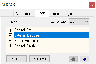
Start the QC Test; click the Add… button on Property Page Tasks to add a new task to your
existing test sequence. Choose the task script exd.task.klb.
The default location is:
%programdata%\Klippel\QC\Scripts\Klippel\QC\Modules
The EXD task will be added to the QC test sequence.
Note
For Bluetooth applications including automated pairing, a second EXD task should be added after the actual measurement steps for unpairing the device.
Creating an EXD Operation (R&D System Framework)#
If you are operating the EXD within the KLIPPEL R&D System framework, you may add an EXD operation to your operation tree using the provided template operation
Create or open a KLIPPEL database
Add a new operation by using the operation icon or
Select and ; you may enter EXD directly in the filter input field to quickly find the correct template
Choose a name and click OK to create a new QC operation
Click Run
 to log in
See dB-Lab Manual for more information.
First Steps#
This section covers the first steps for three different applications of the EXD:
performing a first measurement with the EXD task using an GPIB (IEEE 488.2) compliant digital multimeter,
basic settings for controlling Bluetooth audio devices using a MegaSig U980 interface or
fundamental audio device setup and task settings for Windows Radio based Bluetooth control.
Your First EXD Application#
After adding the new EXD Task to your QC test, you can start with your first measurement.
In Engineer mode you can select the EXD task and edit the task parameters. The relevant parameters for your first measurement are explained in the following paragraph.
See the chapter Task Parameters for more information about all parameters.
Set the configuration task properties and add an entry to the test sequence before running the test. Find more information in the following section.
Click on the Start button in the Control Panel to start your first measurement or use View to change audio device settings first (for sound device or Bluetooth application).
Note
The EXD Task does not provide any measurement functionality using a KLIPPEL Analyzer.
GPIB Control and Testing#
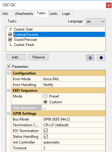
The basic settings for the first measurement via GPIB with the EXD Task are described in this section. Use the default settings of the parameters if not stated otherwise.
Step Sequence#
The test sequence is the central parameter of the EXD Task. It specifies the task’s operating sequence using a simple formatted setup matrix. Every line entry corresponds to one (measurement or control) step.
In order to use GPIB functionality, the custom step sequence must be used. There is currently no sequence preset available. For this reason, set EXD Sequence – Mode to Custom in order to edit the Step Sequence.
In the first example, the DC resistance of a loudspeaker driver shall be measured with a standard IEEE 488.2 (and SCPI) compliant multimeter. The test sequence contains only one line in this case as shown in the screenshot below.
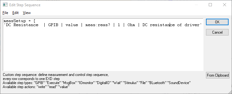
The setup line follows a fixed format, all parameters are | separated. The measure name
is specified in the first entry while the last two (optional) entries represent the measure unit and
a comment. Parameter two and three define the step as a single value measurement performed by a GPIB
device. The actual measurement (and query) command, which is sent to the device, has to be entered
as the fourth parameter. It is followed by the bus address of the DMM.
These entries are sufficient to perform the measurement and create a QC parameter from the result of a 3rd party device.
Bus mode#
This parameter found in category GPIB Settings specifies the used GPIB protocol version. Choose the one which is supported by your devices. This setting is important for the internal initialization and communication with the connected GPIB devices. The IEEE 488.1 standard contains only a small set of common commands and excludes status handling and synchronization. However, this mode should work with any GPIB device. Refer to the operation or programming manual of your device to find out which standard is supported.
For further information about this topic see the specification of the EXD Task (S31 QC – External Devices).
Bluetooth Control (MegaSig U980)#
QC Hardware Configuration#
Playback and Capture Device#
Using the MegaSig U980 analog Bluetooth interface, no special modification of the QC playback/capture settings is required, since the KLIPPEL analyzer is used as the main frontend for input and output. Depending on the selected Bluetooth test template it is possible that a different playback/capture device might be selected. In doubt make sure that Use Default Devices is selected in QC Hardware settings ().
Note
If you are using QC Stand-alone Software together with a 3rd party audio interface, make sure that this is selected accordingly in QC hardware settings of your QC Test.
Automated Line Mode#
In case of errors such as signal drop outs, the test sequences is interrupted and restarted automatically, by default. This behavior is not desired for Bluetooth applications in order to avoid undesired interface or DUT states. Activate the option Automated line mode in QC Hardware settings to make sure that the test is aborted and invalidated for manual restart in case a fatal error occurs. Find more information in QC Manual section Global Test Options.
Bluetooth Interface Settings#
This section addresses the most important EXD settings for Bluetooth audio device handling using MegaSig U9xx interface. Only the simplified setup based on a preset step sequence is introduced.
Select EXD Preset Sequence#
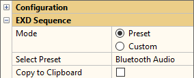
For most Bluetooth control applications including pairing, service activation and unpairing, the preset Bluetooth Audio` shall be selected. The custom EXD sequence may also be used, but it is normally not recommended since the setup is more complicated and susceptible to errors.
Interface Type and COM Port#
Make sure that the Interface Type is set to MegaSig U980 in parameter category Bluetooth – Settings.
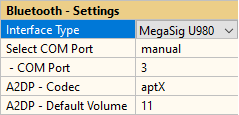
Since the interface is controlled through a USB virtual serial port, it is required to specify the corresponding port number. In case the number is unknown, you may set Select COM Port - automatic in order to find the right port automatically. However, in case other active ports are present, this may degrade timing. Find more information in section Setting Up the Bluetooth Interface.
A2DP Codec and Default Volume#
For acoustic response testing Bluetooth enabled audio devices, normally the A2DP profile is used with the DUT being the audio sink. Both, the preferred codec as well as the playback volume can be controlled by the corresponding parameters in Bluetooth – Settings. The Default Volume can be set to maximum (15) since the actual output level is also depending on the selected test signal level of the following test steps.
You may choose any of the listed codecs but in case the DUT does not support the selected one, the interface will automatically fall back to a supported one. The codec actually used will be displayed in the device information output table after running the EXD.
Note
General settings like switching codec or enabling/disabling profiles cannot be changed during the test sequence since the paired device will be disconnected. For audio testing with dedicated stimulus and analysis the basic SBC codec is mostly preferable due to less complex signal processing compared to more advanced perceptual codecs such as aptX™. Codec artifacts may be inaudible for the human due to masking but may might impact test results. Both distortion and phase tests show to be more stable with basic SBC codec.
Bluetooth Device Settings and Pairing#
Bluetooth – Pairing#
This category provides several parameters to control how a device is selected and paired. You may activate Pair Device and select one of the provided options such as Auto for automatic pairing of the next available device or Friendly Name as well as Address for pairing only the specified device.
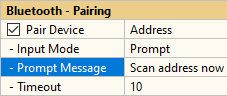
For name or address based pairing you may choose between direct, static input (Input Mode – Enter) or for each tested DUT individually using operator prompt message box input (Input Mode – Prompt). Other ways for importing the device’s address may be realized using the Custom Step Sequence.
Note
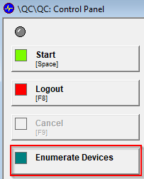
If you do not know the friendly name or address of your device, use auto pairing or activate pairing mode and use the Enumerate Devices button in the Control Panel to list all pairable devices. For optimal performance and minimal probability of confusion it is recommended to use only address pairing. Name-based pairing automatically triggers a necessary device scan (enumeration) before pairing which impairs overall test time significantly.
The parameter Timeout specifies the maximum time period spent for inquiry and/or pairing before an error is raised according to setting Error Mode and Error Handling in Configuration category. User controlled repetition is still possible, depending on those settings.
Note
A dedicated Unpair function is also provided (exclusive with pairing) but redundant in most use cases since the previously tested device is unpaired automatically when the next device is paired.
Using Already Connected Device#
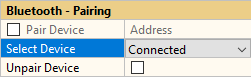
For a single test sequence, it is usually only required to pair and connect the DUT once at the beginning. For example, in case the audio profile shall be switched between A2DP and HFP (e.g. for both speaker and microphone testing in one sequence) a second EXD task is required. However, pairing can be skipped for the second task. The Select Device option allows to use the connected device instead.
Note
Switching A2DP codec is not possible during a sequence since it requires resetting the interface.
Bluetooth-Profiles#
This parameter group defines which Bluetooth profiles shall be enabled and which audio profile shall be active for audio transmission.
Use Select Audio Profile allows to switch between A2DP (Advanced Audio Distribution Profile) profile for stereo playback testing of a Bluetooth sink or bi-directional HFP (Hands-free Profile) for microphone and crosstalk testing.
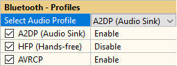
All supported profiles can be generally enabled/disabled using the other available parameters. A2DP is supported by most Bluetooth audio devices and should be enabled for testing acoustic output.
If the DUT is not equipped with microphones or the microphone shall not be tested, it is recommended to deactivate HFP to avoid trouble during pairing. AVRCP is mostly supported and should be enabled, in general.
Note
Enabling and disabling profiles during a test sequence is not possible since the paired device will be disconnected. However, changing active audio profile vie Select Audio Profile with a second EXD task is possible, e.g. to test both speaker and microphone in one sequence.
When the checkboxes are not ticked, the current state of the profile is left unchanged. It is recommended to explicitly enable/disable them, however.
Bluetooth Control (Windows Radio)#
Playback/Capture Device Setup for Bluetooth & Sound Device Application#
For testing Bluetooth or USB audio devices via direct streaming, the QC playback and capture sound device settings must be set accordingly.
In Qc Start Engineer use the View button to open the test or open your Klippel database file manually. Now open the property page Qc Settings and open the Configure Hardware dialog.
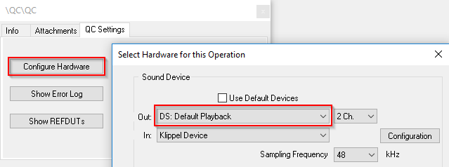
In case you intend to use your DUT as playback device as a sink set Out to DS: Default Playback. This setting corresponds to the Windows Default Playback sound device.
Note
Using Default (Voice) Playback and Capture devices allows swapping the audio device (DUT) during a test session, without reopening the QC test.
Refer to QC Manual section Using Soundcards and Testing Digital Audio Devices for more information about testing digital audio devices.
Basic Settings for Bluetooth Setup#
This section addresses some common settings for Bluetooth audio device handling. Setup is simplified by using a preset step sequence.
Select EXD Preset Sequence#
For most Bluetooth control applications including pairing, service activation and unpairing, the preset Bluetooth Audio shall be selected. The custom EXD sequence may also be used, but it is normally not recommended since the setup is more complicated and susceptible to errors.
Interface Type#
Make sure that the Interface Type is set to Windows Radio in parameter category Bluetooth – Settings.

Bluetooth – Pairing#
This pairing setup is mostly equivalent to MegaSig Bluetooth control. See Bluetooth Device Settings and Pairing for more information.
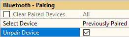
The option Unpair is exclusive to Pair and will remove the last paired or currently connected device (as defined by Select Device).
Note
Using Windows Bluetooth radio it is recommend to unpair the device at the end of the test sequence in order to keep the paired device list clean.
Bluetooth – Profiles#
This parameter category is dedicated to activating and deactivating Bluetooth profiles and services of the connected device (DUT), such as A2DP Audio Sink for testing sound pressure output or HFP for testing the DUT microphone response. Activating AVRCP is required in most cases to make the device recognized as a sound device by Windows.
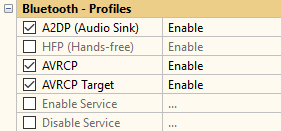
Several typical audio-related profiles can be simply activated or deactivated. Use Enable/Disable Service parameter to (de)activate other services by their UUID.
Note
If you do not know which profiles are supported by your device, you may pair your device
manually via Windows Bluetooth dialog and use the Enumerate Devices button of the Control
Panel to list all connected devices and the corresponding services.

Error Handling#
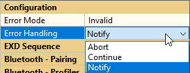
Since timing in Bluetooth pairing and control can be very variable and usually also includes some manual steps (e.g. activating pairing mode on the device), it is recommended to set Error Handling to Notify in order to give the operator the chance to retry the last failed step or to continue/abort if necessary.
Basic Settings for Sound Device Setup#
The parameter section Sound Device Settings provides common settings for audio device handling that apply to Bluetooth audio devices, soundcards or any other digital audio device.
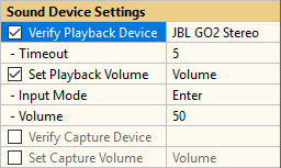
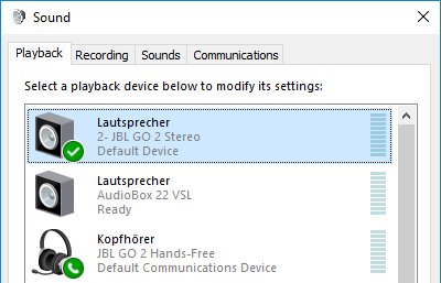
If you use Default (Voice) Playback or Default (Voice) Capture Sound Device, you should use the Verify… option to check that the intended device is actually selected as default device in Windows Sound Device settings. You may enter the clear name of the device as shown in Windows Sound oanel.
The Timeout can be used to wait for a certain time before aborting (e.g. after pairing a Bluetooth device).
You may also use the Enumerate button in the Control Panel to list all available audio devices and check the default device status.
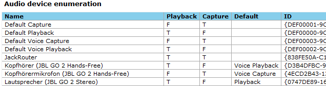
The Set Playback/Capture Volume option allows to control the playback and capture volume or level. The value corresponds to the stated values in Windows Sound panel.
Viewing Results#
In case your EXD task is configured to generate results (e.g. GPIB measurement step), they will be shown in the Summary window after running the test.
The output is structured into different tables showing the measured single value results, read messages, errors and the connected hardware according to the general settings and the measurement setup matrix.
The Summary window below shows the results of the first measurement with limits.
It directly indicates whether the test has passed or failed. To pass the test means that the measured parameters are all within the defined limits. In case any result failed, the corresponding entry is highlighted red.
See Working with Limits for details about creating and adjusting limits.
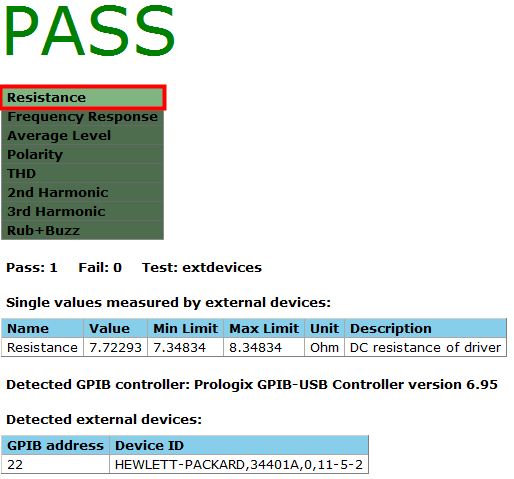
The EXD Task generates the first result Resistance while the other measures are results of the following SPL task.
The table below the verdict list shows the measurement results and the limits applied.
Information about the connected GPIB controller and the detected devices is given below the results.
Note
Full GPIB device initialization (status registers) and ID query is only available in IEEE 488.2 mode.
Working with Limits#
In the QC Engineer mode, the user is enabled to set tolerance limits for the QC test using Limit Calculation Mode.
While this mode is activated, each selected measurement will become a reference and the limits for further measurements are derived from these reference values. The measurement results of each DUT (device under test) are then checked against these limits to extract a Pass/Fail decision.
Skip this section in case you use the EXD only for control purposes that do no generate result data.
Measuring Reference Units#
Open a test in Engineer mode and choose proper setup parameters and specify the test sequence. Limits can only be applied to “value” or “read” steps.
Select Limits tab in Properties window and click Activate Limit Calculation Mode.
Now start the measurement by clicking the Start button in the control window. An arbitrary number of reference units/measurements can be collected, as long as the Limit Calculation Mode is activated.
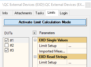
Limit Setup - Single Values#
Before the limits can be calculated the limit setup matrix single measures must be specified according to the test sequence.
The structure of both setup matrixes is similar, but the limit matrix only contains measurement
steps (step action: value) as shown in the picture below.
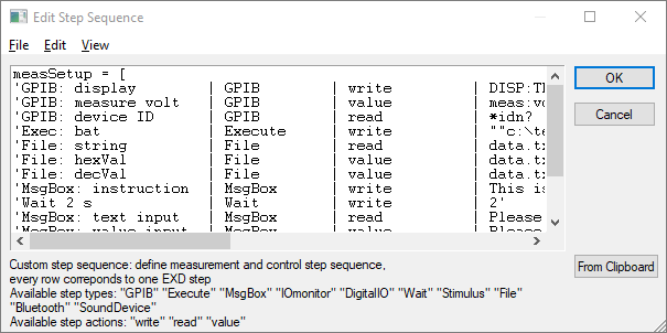
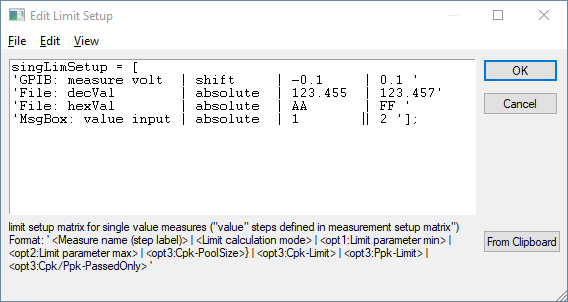
The line order does not have to correspond to the Test sequence; only the measure name/label must be identical in both matrixes. Missing entries will deactivate the limits for the concerning measure.
For each measure there are three limit parameters. The limit type is set in the second column of the setup matrix. It is followed by the upper and lower limit parameters, which are interpreted according to the limit type.
Four limit types are available:
- Relative
Tolerance (upper and lower) is the percentage the measured parameter may in relation to the average value of the reference units
- Statistic
Sigma (upper and lower) is the standard deviation factor for a uniform distribution of measurement values
Statistic limit calculation is only reasonable for more than one measured reference units.
- Absolute
Gives absolute values for the upper (=max) and the lower (=min) limit.
This value is independent of the average value of the reference units
- Shift
The shift value is added to the average value of the reference units for the upper limit and subtracted from the average value for the lower limit.
Note
No limits (upper or lower) are applied if the relevant parameters are left empty. This results in a neutral (gray) verdict or only upper or lower limit check.
Calculating Limits#
When the amount of reference units is sufficient and the limit parameters are set, deactivate the Limit Calculation Mode by clicking Activate Limit Calculation Mode again or press Calculate. The tolerance limits for valid DUTs are now calculated according to the settings and displayed in the summary window as shown below.

All following measurements will be checked against these limits.
For additional information about limit calculation mode see Limit Calculation.
Reference DUT Check#
To ensure the validity of the calculated limits all measured reference DUTs are checked against these limits automatically after deactivating Limit Calculation Mode. In case any reference DUT fails the check, the summary window shows additional information as shown below.
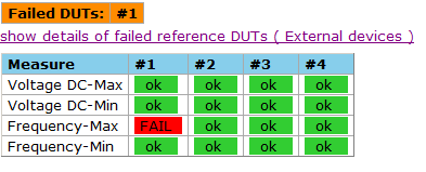
All failed reference DUTs are listed. To identify the failed measure a hidden table shows the single verdicts. To solve this conflict, go back to Limit Calculation Mode and either remove the concerning reference unit from the reference DUT list or readjust the limit settings.
Limit Setup - Read Strings#
The limit handling described so far, applies to measured values that are interpreted as numbers
(step action: value).
To check arbitrary conditions that are available as character string messages (e.g. Digital IO state
or GPIB query) read steps are also supported for limit handling. This is done by simple comparison
with a target string. Therefore, a second limit category EXD Read Strings is available in the
limit property page as shown below.
In the simple setup matrix two parameters are available. In the example below the first step parameters are not specified and no limits are generated.
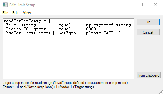
In the last column the target character string to be compared is specified. The limit mode in the
second column determines if the read value has to be equal (equal) or unequal (notEqual) to the
specified target string for PASS verdict.
All steps specified here will create a task result, which will be shown in the verdict list of the Summary window.
Note
No limits/check is applied if one of the parameters is left empty or of the concerning step is not listed in this matrix. The corresponding step will be passive (neutral verdict).
Testing Your First Device#
Once you have created limits, you may run a first test.
If the results are within the tolerances, all tests will pass and the Summary window will show PASS as the overall verdict. If a measurement result violates the tolerance range or a read message does not fit the target, the relevant entry will be highlighted red in the Summary window. This results in an overall FAIL verdict as shown in the example below.
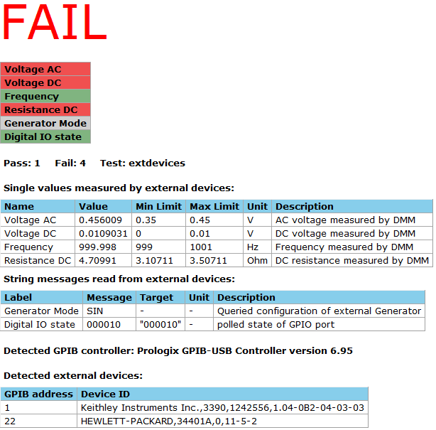
If no limits were specified the particular result will be highlighted gray in the verdict list
Optimizing the EXD Task#
Working with Different Step Types#
This section focuses on the application of the different step types provided by the EXD Task using the EXD Step Sequence.
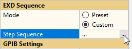
Using the Preset mode, some typical applications are be covered without using custom sequence. This can speed up the setup process for straight-forward scenarios significantly.
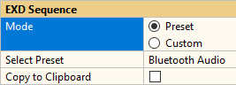
Note
Some sequence presets may be operated without any required software license. However, in order to use custom sequences, an EXD Pro license is mandatory. Other functionality like Bluetooth handling might be licensed individually.
The EXD Step Sequence#
Overview#
The Step Sequence matrix available in the EXD property page is the most important parameter of the EXD Task. It defines and configures the step sequence to be performed including hardware control and measure definition. The plain ASCII string (vector) input in the text editor window follows a fixed format and provides high flexibility in configuring the sequence.
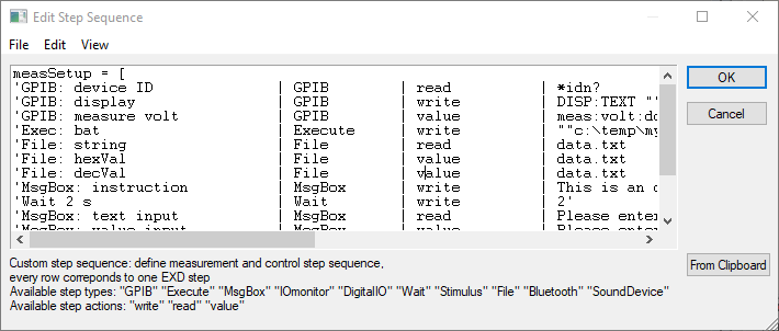
Note
The setup matrix can also be created, edited and saved using external text editors.
To prevent input syntax and format errors the whole matrix is checked after editing and closing the internal editor.
General Step Format#
Every line entered in the setup matrix corresponds to one independent test step. The entry format consists of mandatory and optional parameters, depending on the step type and action performed:
' <Label/Name> | <Step type> | <Step action> | <Parameter 1> | <opt:Step parameter 2> | <opt:unit> | <opt: comment> '
Each line must not have more than 1024 characters. One step can be defined over multiple lines by
adding the line break … at the end of one line (before the quotation mark). Whole lines can be
commented out by starting the concerning line with // (after the quotation mark).
In any case a step label or a measure name have to be specified in the first of the | separated
columns. The step type selects the mode/interface (etc. GPIB or Windows Command Processer Shell) while step action
determines the input/output behavior.
Note
Any additional quotes used within the quoted expression must be escaped by a second quote (''...'')
Available step types are:
GPIBBluetoothSoundDeviceDigitalIOIOmonitorWaitMsgBoxExecuteFileStimulus
Three actions are available:
writereadvalue
Not all actions are available for all step types. Please refer to Task Parameters or the following
paragraphs for further information. Step action write declares a write-only step - no external
data is read. Read can be used to read arbitrary character string data while value focuses on
reading numerical string data (single value) to create a QC result.
The purpose of step parameter 1 and 2 are determined by the step type and action.
The last two columns of the setup matrix optionally specify a unit label and a comment for
the result tables in Summary window. These parameters are obsolete for write-only steps (write).
The following sections discuss the format and application of the different step types in detail.
GPIB#
Application#
This step type is used for controlling and querying external devices via GPIB. Within one step one device on the bus can be written and queried for control and measurement. Therefore, a user defined GPIB command sequence is sent to the device. All status handling for synchronization and error handling is performed internally, if activated.
Step Format#
The test sequence line entry for GPIB steps requires the following parameters:
' <Label/Name> | GPIB | <Step action> | <GPIB command sequence> | <GPIB address> | <opt: unit> | <opt: comment> '
All step actions are available. The GPIB command sequence can be specified freely using device dependent commands or SCPI syntax. It is sent to the device without any changes. Please refer to the programming manual of your device to find out about supported commands.
Controlling a Device#
Step action write is used for pure device setup and control. In this case the GPIB command
sequence must not contain query commands (terminated by ?) to avoid query errors, because the
output buffer of the device is not read. The task is suspended until the device sets operation
complete flag (only if status handling is activated) or timeout occurs.
Example#
Configuring a DMM for DC voltage measurement
' Config DMM | GPIB | write | CONF:VOLT:DC | 22 '
Querying a Device#
If the device is addressed to measure, step action value is required. In this case the GPIB
command sequence has to be terminated by a query command (terminated by ?). The data, which is
read from the device’s output buffer, is interpreted as a single numerical value and a QC result is
generated. It will be available for limit calculation. See Limit Setup - Single Values for further
details.
If status handling is activated the message available flag (MAV) is used for synchronization. Otherwise the device is read until the termination character is received or timeout occurred.
Example 1#
Triggering measurement and reading result from output buffer
' Voltage DC | GPIB | value | INIT;:FETC? | 22 | V | DC voltage measured by DMM'
Only querying plain character string messages can be achieved with step action read. The read data
is not interpreted as numerical data. It is written to the result table unchanged. Limit handling is
restricted to simple string comparison with a target string (see Limit Setup - Read Strings).
Example 2#
Querying device ID
' Query ID | GPIB | read | *idn? | 22 | | Device ID '
Note
Any GPIB data is received as a sequence of characters. Thus, all query responses can be
handled with read steps. Only value steps interpret the data numerically and thus it has to be
in a numerical format.
Bluetooth#
Application#
This step type provides functionality pair/connect and control Bluetooth audio device either via Windows Bluetooth stack or MegaSig U9xx Bluetooth interface. While Windows radio comes integrated with almost every PC or is enabled with a cost-efficient USB dongle, the MegaSig interface is recommended for trouble-free, efficient and simple operation.
Note
It is recommended to use the sequence preset Bluetooth Audio for handling Bluetooth devices. Please refer to section EXD – Tutorial for more information.
For Windows radio, several audio related profiles (e.g. A2DP, HFP) are predefined. The functionality is closely related to the manual operation in the Windows Bluetooth & other devices dialog. All actions performed by the EXD Bluetooth step are reflected here.
After pairing and service activation, the audio device will be available as playback and/or capture device in Windows Sound panel. Use the step Sound Device to verify correct pairing and volume control.
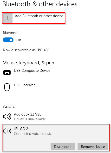
Step Format#
The test sequence line entry for Bluetooth steps requires the following parameters:
' <Step Name> | Bluetooth | write | <command> | <argument> '
No data is returned here. Therefore, only step action write is available. The first parameter
<command> defines the actual action performed while the second custom parameter carries the argument
such as device address, name or service ID. Step variables can be used to pass dynamic arguments
like the current address of the current device that has been entered through a prompt dialog in an
earlier step. Refer to Step Parameter 1 and Step Parameter 2 for more details.
Example#
In this example, the next available device with the name “JBL GO2” will be paired and the A2DP audio sink and AVRCP profiles are activated.
'Pair with device | Bluetooth | write | Pair Name     | JBL GO2'
'Enable profiles  | Bluetooth | write | Start Service | AudioSink, A/V_RemoteControl'
Sound Device#
Application#
This step type is dedicated to general sound device interaction like playback/capture volume control or verifying device name before testing. This applies to all audio devices that provide an ASIO driver or WDM devices available in Windows Sound devices panel such as USB sound cards or speakers but also for Bluetooth devices connect via Windows Bluetooth Radio (see step Bluetooth).
Note
It is recommended to use the sequence preset Sound Device Handling for controlling audio devices. Please refer to section EXD - Tutorial for more information.
Step Format#
A SoundDevice step requires the following parameters in the EXD Sequence:
' <Step Name> | SoundDevice | <step action> | <command> <opt: device name> | <argument> '
The main step action for device control is write, but other step actions are available for querying device names or volume setting. The argument parameter is provided for specifying values like target volume or wait time for timeout. Refer to Step Parameter 1 and Step Parameter 2 for more details.
Example#
In this example the first step checks whether the currently selected Windows Default Playback Device is the audio device JBL GO2 Stereo. The timeout to wait until the step fails (e.g. after establishing Bluetooth connection or plugging the device) is 5 seconds.
In the second step, the global system playback volume is set to 50 %.
'Check Playback Device | SoundDevice | write | Playback Device JBL GO2 Stereo | 5'
'Set Playback Volume   | SoundDevice | write | Playback Volume                | 50'
Digital I/O#
Application#
This step type controls the GPIO of the KLIPPEL Analyzer device as well as the virtual representation via software Automation interface. It can be used to control automation or peripheral hardware (e.g. switching multiplexers) or read status information via input pins. In total there are nine user definable outputs and six inputs available. Find details about the GPIO in the QC User Manual section I/O Connector.
Step Format#
Test sequence entries for Digital I/O steps require the following parameters:
' <Label> | DigitalIO | <Step action> | <Output pin values> | <opt:Mask> | - | <opt: comment> '
Only write and read actions are supported here. The parameters Output pin values and Mask
are used to set the output pins. Therefore, they are obsolete for input pin polling (read).
Setting Output Pins#
The GPIO offers nine user output pins. The following table shows the corresponding hardware pins of the I/O connector.
User Output |
Pin |
|---|---|
Out1 |
Pin 24 |
Out2 |
Pin 11 |
Out3 |
Pin 5 |
Out4 |
Pin 17 |
Out5 |
Pin 4 |
Out6 |
Pin 16 |
Out7 |
Pin 3 |
Out8 |
Pin 15 |
Out9 |
Pin 2 |
Note
Pin 11 is not available if temperature/humidity sensor is connected at start-up
Setting a sub-group of the GPIO outputs requires specifying the Boolean values (parameter Output pin values) and the corresponding mask (parameter Mask). The mask specifies which pins shall be set and which should stay unchanged. For both parameters the nine output pins are represented by a bit sequence. All pins are set if no mask is specified.
Example#
Setting output pins 1, 5 and 6; all others hold old state (“?”)
' Set GPOut | DigitalIO | write | 100010000 | 100011000 '
The resulting output state would be:
Value:    1 0 0 0 1 0 0 0 0
Mask:     1 0 0 0 1 1 0 0 0
Output:   1 2 3 4 5 6 7 8 9
Result:   1 ? ? ? 1 0 ? ? ?
Optionally, the mask can be included in parameter 1. If a pin shall hold its previous state, mark
this pin with an x, according to the example below. In this case parameter 2 is ignored.
Example#
Setting output pins 1, 5 and 6; all others hold old state (?)
' Set GPOut | DigitalIO | write | 100010000 | 100011000 '
The resulting output state would be:
Value:    1 x x x 1 0 x x x
Result:   1 ? ? ? 1 0 ? ? ?
Polling Input Pins#
The GPIO offers six user input pins. The following table shows the corresponding hardware pins of the I/O connector.
User Input |
Pin |
|---|---|
In 1 |
Pin 10 |
In 2 |
Pin 22 |
In 3 |
Pin 23 |
In 4 |
Pin 8 |
In 5 |
Pin 7 |
In 6 |
Pin 19 |
Note
Pin 7 Used to start measurement
Pin 19 is not available if temperature/humidity sensor is connected at start-up
Polling the state of the input pins returns a bit sequence starting with In 1. All set bits are
represented by 1; otherwise the value is 0.
Example#
Polling input pins
' Poll GPIn | DigitalIO | read '
A possible result could be:
Result:   0   1   0   0   1   0
Input:    In1 In2 In3 In4 In5 In6
State:    off set off off set off
Limit handling is restricted to simple string comparison with a target bit sequence (see Limit Setup for Read Strings).
The target string has the same format as the input bit sequence. However,
for this step type also a read mask may be applied according to output pin setting. The pins that
shall be ignored must be replaced by an x in the target string according to the example below.
Example#
Limit setup:
' Poll GPIn | equal | 01xx10 '
In this case only pins 1, 2, 5 and 6 are compared.
IO Monitor (Legacy)#
Application#
The I/O Monitor API is a legacy software API for remote control of the Klippel QC. It can be used in addition to the GPIO of the KLIPPEL Analyzer.
With the step type IOmonitor you can send data to your I/O monitor application. Make sure that I/O Monitor support is activated and the correct ID is specified in the QC Hardware Setup (see QC User Manual section Hardware Configuration).
Step Format#
Test sequence entries for IOmonitor steps require the following parameters:
' <Label> | IOmonitor | write | <channel value mask aux> '
No data is returned here. Therefore, only step action write is available. Only one parameter is
available specifying one line of the ExternOut matrix, which consists of four entries (channel,
value, mask and aux) to be entered space separated.
Example#
' Write IO mon | IOmonitor | write | 5 20 13 0 '
Please refer to the I/O Monitor API documentation for further details.
Wait#
Application#
This step type can be used to suspend the execution of the step sequence by a specified time.
Step Format#
The test sequence entries of Wait steps require the following parameters:
' <Label> | Wait | write | <time in s> '
No data is returned here. Therefore, only step action write is available. Only one parameter is
available specifying the time to wait in seconds (decimal fraction).
Example#
Wait for 500 milliseconds
' Wait 0.5 | Wait | write | 0.5 '
Message Box#
Application#
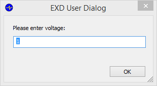
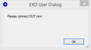
The step type MsgBox generates a message box for operator instructions and data input. A user definable text is displayed and an optional user input field can be used for single value or text input. The test sequence is suspended until the message box is terminated with the “OK” button.
This step type can be used to synchronize manual operator interaction within the sequence (e.g. connecting DUT) or to manually input external test results or auxiliary data.
Step Format#
The test sequence entries of MsgBox steps require the following parameters:
' <Label> | MsgBox | <Step action> | <message> | <opt: initial input> | <opt: unit> | <opt: comment>'
All step actions are available. Parameter specifies the message, which shall be shown in the message
box. The second parameter is optional and only used for step actions read and value. It defines
the initial value displayed in the text input field of the message box.
Example#
Create a message box showing “Please connect the DUT”
' Msg: Connect DUT | MsgBox | write | Please connect the DUT '
Create a message box for external test data input (initial input value 1)
' Query voltage | MsgBox | value | Please enter voltage | 100 | mV | '
Create a message box text input (initial input value “PASS”)
' Query verdict | MsgBox | read | Please enter inspection verdict | PASS '
Command Line Execution#
Application#
The step type Execute executes arbitrary file commands in the Windows Command Processer Shell. External programs or batch files including parameters can be executed in the background. The step sequence is suspended until the command or called program is terminated.
To provide further information about the current test, environment variables are created which will be available during execution. These variables represent a selection of internal system variables:
Cfg_DatabasePathCfg_DutStartTimeCfg_LimitCalcModeCfg_LimitCalibModeCfg_LimitsAvailCfg_LoginModeCfg_MonitorIDCfg_PCNameCfg_SerialNumberCfg_SpeakerCfg_UserNameCtrl_ErrorGeneral
Example code:
' echo DUT serial number: %Cfg_SerialNumber% ''
Step Format#
The test sequence entries of Execute steps require the following parameters:
' <Label> | Execute | write | <path> <arg1> … '
No data is returned here. Therefore, only step action write is available. Only one parameter is
available specifying the command line to be executed in the Windows Command Processer Shell. Use quotation marks in
<command> in case paths or files contain white space.
Example#
Call batch file
' Call bat | Execute | write | ``C:\my folder\test.bat´´ ``my argument´´ '
Data Import from Text File#
Application#
The most flexible and simple way for exchanging testing data or auxiliary information is a plain formatted text file which can be created easily by third party software. The step type File allows importing a single value number or a character string from a text file.
File Format#
The file containing the data to be imported must fulfill a simple but defined format which equals the general parameter and limit import file format. Please refer to section Settings and Limit Import for more information.
Only single value decimal or hexadecimal data is accepted for import. Other data may be imported as a character string, alternatively.
Note
The text file may contain other data as long as it fulfills the general format
requirements. Hexadecimal values must be quoted and contain an identifier prefix 0x of suffix h
(e.g. 0x34 or 34h). Please note that values exceeding 224 may not be handled with full
precision.
Example#
This is the content of an example text file “import.txt”:
//This is a comment
myString = ''my string''
myValue  = 123.456
myHexVal = ''0xF6''
Step Format#
A File step is defined as follows:
' <name> | File | <action> | <file path> | <var name> | <opt: unit> | <opt: comment>'
<name> defines the output variable name while <var name> refers to the variable name in the source
file. The location of the source file can be defined as an absolute file path or relative to the
current test folder. Parameter <action> defines whether the source value is interpreted as a
numerical value or a character read.
Example#
This example applies three File steps to import two numerical values and a character string from
two different source files:
' Voltage | File | value | C:\MyFolder\import.txt | myValue  | V | imported V '
' Address | File | value | C:\MyFolder\import.txt | myHexVal |   | device addr. '
' Info    | File | read  | MySubFolder\import.txt | myString'
Stimulus#
Application#
This step type uses the internal signal generators of the QC or imported wave files for playback via the KLIPPEL Analyzer Hardware hardware. The stimulus signals can be looped for continuous playback during the following steps (e.g. for simultaneous measurement) until stopped or the sequence is finished.
Step Format#
The test sequence entries of Stimulus steps require the following parameters:
'<Label> | Stimulus | write | <config> | <routing>'
No data is returned here. Therefore, only step action write is available. The parameter <config>
configures the generator using an SCPI related syntax. The output routing of the signal is defined
by <routing>. Refer to Step Parameter 1 and Step Parameter 2 for more details.
Example#
Creating a multi-tone signal
' Gen: MT | Stimulus | write | MULT 100, 5000, 20, 0.5, 1 | Out1 '
Playback and loop external file
' Gen: MT | Stimulus | write | WAV “C:\temp\test.wav”, 0.5, loop | Sp2 '
Stop looped playback
' Gen: MT | Stimulus | write | OFF '
Note
One stimulus step lasts one loop of the specified stimulus duration. The sampling frequency of the imported wave file must be equal to the selected sampling frequency of the current test (default: 48 kHz). In case of stereo files only the left channel is used for playback.
Example Sequences#
DMM Sequence#
- Task
Measure frequency and AC voltage with multimeter (GPIB address 22)
configure devices
set and read GPIO
set IO monitor
instruct operator.
- Step Sequence
measSetup = [
'set display 1 | GPIB      | write | DISP:TEXT ‘‘Running’’ | 22'
'message       | MsgBox    | write | Please press red button. '
'Set IO pins   | DigitalIO | write | 010000              | 011000'
'start batch   | Execute   | write | C:\Temp\test.bat'
'wait 2s       | Wait      | write | 2'
'Frequency     | GPIB      | value | MEAS:FREQ?         | 22 | Hz | … frequency measured by DMM'
'Voltage (AC)  | GPIB      | value | CONF:VOLT:AC 10, 0.003;:INIT;:FETC? | 22 … | V | AC voltage measured by DMM '
'read IO pins  | DigitalIO | read'
‘write IO mon  | IOmonitor | write | 1 2 2 0’
'set display 2 | GPIB      | write | DISP:TEXT ‘‘Complete’’ | 22 '];
External Signal Generator#
- Task
Configure external signal generator @ GPIB address 1
- Step Sequence
'Generator:Sinus | GPIB | write | APPL:SIN 1000, 1.4 Vpp, 0 | 1 '
Using Variables#
For certain step types and parameters, it is possible to exchange data between EXD steps using sequence variables. This can be used to use data that is obtained dynamically during the sequence (e.g. Bluetooth address entered by operator before pairing). The variable name corresponds to the name of the source step and it is used according to the format:
{var:<source step name>}
Allowed source steps are:
GPIB, MsgBox, File, SoundDevice
Allowed receiving steps are:
Execute, MsgBox, Bluetooth, SoundDevice
Note
variables can only be used in certain parameters in each step type. Any invalid use will be notified by an error in the EXD property page.
Example#
Bluetooth pairing address input via bar code scanner (operator prompt)
'BT address | MsgBox    | read  | Please scan address | '
'Pairing    | Bluetooth | write | Pair Address        | {var:BT address}'
Debugging Your GPIB Sequence#
Setting up a complex measurement and control sequence using multiple devices can be realized easily using the EXD Task. However, the more complex the whole test gets, the more likely are errors to occur due to configuration or command errors and dynamic step interaction. Especially for GPIB communication the sources of errors are manifold.
This section discusses possible ways for debugging your test sequence.
Tracking the Error Source#
Device Initialization Errors#
Before executing the test sequence, the controller and all requested GPIB devices are initialized.

In this case an error in the device setup and connection or the EXD Task’s Configuration Parameters is most likely. Please refer to GPIB Controller Errors find out about possible causes and remedies.
The EXD Step Sequence does not influence the initialization except for the GPIB address (Step Parameter 2). The GPIB device list is derived from the addresses specified in the sequence. You may check the validity of the entered value.
Errors and Warnings During Sequence Execution#
All errors and warnings that may occur during the execution of the test sequence are accumulated and shown in a table in Summary window as shown below.

The tables indicate the concerning step numbers and device addresses. Additionally, the column Error message specifies error details. Please see Error Messages for details.
Prologix GPIB Configurator#
The Prologix GPIB configurator is a powerful external tool for debugging and testing GPIB commands with the Prologix GPIB-USB controller is. It is available for free with KE5FX GPIB toolkit.
This terminal program is useful to check the controller connection, to check device compatibility and to test single commands or measurement steps with your GPIB devices before setting up the EXD Task test sequence to minimize possible errors.

Manipulating the Enable Registers (Status Reporting)#
Activating status handling for IEEE 488.2 compliant devices enables the GPIB status reporting system. The majority of the device independent status bits are activated (enable register) to be forwarded to the status byte register. Please refer to the specification (S31 QC – External Devices) of this module for further information about the internal settings.
In some cases, it might be desirable to activate or deactivate certain status bits. This might be the case if certain warnings shall be blocked or device specific status information shall be integrated.
For this purpose, the standard command set according to the table below can be included in your test sequence.
Enable register |
Query command |
Set command |
|---|---|---|
Status byte |
|
|
Questionable data |
|
|
Standard event |
|
|
The current setting is queried by appending a question mark to the command (e.g. *ESE?). Setting
and querying the enable registers is performed with decimal numbers (<value>) representing the
summed binary values of the bits that are set in the concerning enable register.
Modifications in the status reporting system should be performed at the beginning of the test sequence.
Note
It is recommended to keep the standard settings for best functionality. In any case the status byte register should not be modified to avoid errors when status handling is activated.
Example 1#
Querying the questionable data enable register from device at address 22.
Step command:
' Query ENAB | GPIB | value | STAT:QUES:ENAB? | 22 '
Result:
“32767” = 20+21+…+214 = 215-1
(Bits 0 … 14 out of 15 are enabled)
Example 2#
Deactivating bit 9 of the questionable data enable register of device address 22 (e.g. to suppress a minor warning that may be represented by this bit).
Value: 215-29 –1 = 32255
Step command:
' Set Reg | GPIB | write | STAT:QUES:ENAB 32255 | 22 '
Optimizing Speed (GPIB Application)#
Including external device communication in a QC test may slow down overall test time. Especially device communication via GPIB can be time consuming due to synchronization including measurement, setup, processing and communication. Nevertheless, there are some issues that should be taken into account to improve time performance.
General Issues#
Before including the EXD task in an existing task sequence, the task number and order should be considered. The EXD task is most efficient using as few instances as possible in a task sequence. Especially when GPIB devices are addressed, the device initialization may be performed multiple times with every instance of the EXD task in the task list.
Due to efficient processing and the variability of the test sequence, complex sequences can be executed efficiently using only one EXD task. Thus, the whole test should be set up efficiently to reduce the total number of QC tasks. For example, a significant part of the IO Task functionality, such as message box handling is also available in the EXD task. For this reason, it can be included directly in the task’s test sequence instead of employing an IO Task in between two EXD Tasks.
Manual Controller Initialization#
Using GPIB the Prologix GPIB-USB controller is initialized automatically by default. The controller behaves as a virtual serial port. Therefore, during automatic initialization, all available COM devices are scanned to identify the controller. Manually specifying the COM port number of the controller saves initialization time. This option is available in the task properties as shown below.
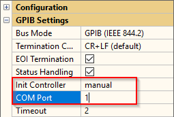
See Setting Up the GPIB-USB Controller to find out or modify the COM port number of your controller.
Multiple GPIB Measurements#
GPIB device initialization e.g., after switching the measurement mode of a multimeter may be very time consuming. Therefore, switching measurement modes within one sequence should be minimized.
Furthermore, the configuration and the measurement should be separated if the same measurement is
performed multiple times. Complex GPIB commands such as MEAS:…? should be avoided in this case
because configuration, measurement and output are initiated by these commands. Configuration,
measurement trigger and data acquisition can be performed separately using more specific commands.
In the following example, a multiplexer is switched multiple times and the resistance is measured each time after switching. Both sequences deliver the same results but the execution time may differ significantly:
Example 1 (slow)#
' Switch 1    | DigitalIO | write | 000000001 | 111111111 '
' Resistance1 | GPIB      | value | MEAS:RES? | 22 | Ohm '
' Switch 2    | DigitalIO | write | 000000010 | 111111111 '
' Resistance2 | GPIB      | value | MEAS:RES? | 22 | Ohm '
' Switch 3    | DigitalIO | write | 000000011 | 111111111 '
' Resistance3 | GPIB      | value | MEAS:RES? | 22 | Ohm '
Example 2 (fast)#
' Switch 1    | DigitalIO | write | 000000001   | 111111111'
' Config DMM  | GPIB      | write | CONF:RES '
' Resistance1 | GPIB      | value | INIT;:FETC? | 22 | Ohm '
' Switch 2    | DigitalIO | write | 000000010   | 111111111'
' Resistance2 | GPIB      | value | INIT;:FETC? | 22 | Ohm '
' Switch 3    | DigitalIO | write | 000000011   | 111111111'
' Resistance3 | GPIB      | value | INIT;:FETC? | 22 | Ohm '
EXD – Reference#
Task Parameters#
Configuration Parameters#
The table below lists all available configuration parameters of the EXD task. There are some general configuration parameters that control the general task behavior as well as subgroups for different step types (e.g., GPIB device communication).
Category: Configuration#
Error Mode#
This setting defines the impact of errors that may occur during execution of the step sequence on the final test verdict.
Available settings are:
Force FAIL
Ignore
Warning
Invalid
Selecting Force FAIL will result in a FAIL verdict. Ignore leads to a VOID verdict (grey color) and Warning creates a WARNING verdict (yellow color). Invalid triggers an INVALID overall verdict.
In any case the suffix “Error” is appended to the step result to distinguish errors from regular verdicts due to the measurement results.
Error Handling#
This setting determines the consequence of errors on the further execution of the sequence:
Abort
Continue
Notify
Selecting Abort immediately cancels the test sequence after the step where the error occurred. In case of Continue, the whole sequence is executed and all error messages are accumulated. Selecting Notify will trigger a message box in case of error, giving the operator the opportunity to retry, ignore the error or abort the test (not available for all step types and actions).
Digital Out (amp check)#
Set bit mask for digital outputs during amplifier check.
Rows correspond to pins 24, (11), 5, 17, 4, 16, 3, 15, 2
Format 1:
[Value1, Mask1; Value2, Mask2; ...]
Format 2:
[Value1; Value2; ...]
Note
This setting may be overwritten by other tasks in the test sequence requesting amp check. Only one digital output mask may be defined for amplifier check in the test sequence – use the same mask if multiple EXD tasks are used.
Import Parameters#
This checkbox activates task and limit parameter import from external parameter file.
Please refer to chapter Settings and Limit Import for more information.
Parameter file#
Absolute or relative file path of .klpar parameter file for import of settings and limits.
Any relative path entered will be related to test folder as base path.
Category: EXD Sequence#
Mode#
Select whether you want to use a custom EXD Sequence or one of the provided Sequence Presets.
Step Sequence#
This text input field defines the custom step sequence of the EXD. Refer to section EXD Step Sequence for more information in case Mode is set to Custom.
Select Preset#
Select one of the available sequence presets for simplified setup in case Mode is set to Preset.
Copy to Clipboard#
Copy preset sequence to clipboard. The sequence may be edited and pasted in custom Step Sequence.
Category: GPIB Settings#
Bus Mode#
This parameter specifies the instrumentation bus, which is supported by your devices. The bus mode determines the internal communication protocol, initialization and synchronization with the connected devices. Currently only GPIB is supported. Using GPIB requires Prologix GPIB-USB bus controller connected to your PC.
The available modes are:
none
GPIB (IEEE 488.1)
GPIB (IEEE 488.2)
Select none if no GPIB device is used or connected to deactivate hardware initialization.
Selecting basic IEEE 488.1 protocol guarantees highest device compatibility but functionality is limited.
IEEE 488.2 supports a set of mandatory standard commands as well as status handling to ensure synchronization and handle errors. The EXD Task complies the common functionality for device communication internally.
See the task specification S31 QC – External Devices for further information.
Termination Character#
The GPIB command termination character is specified here. The selected character is appended to any GPIB command sent by the controller to your connected devices. The available characters are:
CR + LF (carriage return + line feed)
CR
LF
Please refer to your device manual to find out which termination character is required and supported. Most common is appending both available characters.
This parameter is only available for .
EOI Termination#
Enables assertion of EOI hardware line signal with the last character of any command sent via GPIB. Most devices require EOI signal in order to properly detect the end of a command. This feature should be activated in the default case.
This parameter is only available for .
Status Handling#
Enables the internal support of IEEE 488.2 compliant status system. The status system requires a standardized register structure supported by the connected devices. This feature should be activated if supported by your device to ensure synchronization and error handling during GPIB communication.
See the task specification S31 QC – External Devices for further information.
This parameter is only available for .
Init Controller#
The initialization mode of the GPIB bus controller is selected here. The Prologix GPIB-USB controller is connected to the system as a virtual serial port. Therefore, the EXD Task requires the COM number of the virtual serial port. It is determined automatically selecting automatic. Otherwise the port number has to be specified manually (parameter COM port), which is recommended for time efficiency.
This parameter is only available for .
COM port#
The virtual serial port (COM) number of the GPIB-USB bus controller is specified here. It can be found and changed in the Windows Device manager.
This parameter is only available for .
Timeout#
The Read timeout specifies the global time span for communication timeout in seconds. This value applies for virtual serial port access and reading GPIB devices (bus timeout, reading output buffer, waiting for status flags). If a timeout occurs, errors are generated and affected measures are handled according to Error mode settings.
Category: Bluetooth Settings#
Interface Type#
Select Bluetooth interface
Windows Radio
MegaSig U980
Select COM Port#
Virtual serial port selection of MegaSig Bluetooth interface
automatic: automatically detect COM port
manual: select COM port manually
This parameter is only available for .
COM Port#
Enter COM port number of the Bluetooth control interface
This parameter is only available for .
A2DP – Codec#
Select preferred Bluetooth codec used for A2DP profile:
SBC
aptX™
aptX™ LL
aptX™ HD
If the selected codec is not supported by the DUT, the codec will fall back according to the listed order (from bottom)
This parameter is only available for .
A2DP – Default Volume#
Set default playback volume for A2DP audio sinks (0 … 15)
Category: Bluetooth Pairing#
Clear Paired Devices#
Clear (unpair) paired Bluetooth device list
all: clear all - also unpair all connected devices
remembered: only clear devices that are currently not connected
Warning
This will clear all Bluetooth devices that have been paired with this PC (not only audio)
This parameter is only available for .
Wait After#
(Optional) Time to wait after unpairing, if connected devices have been removed
This parameter is only available for .
Pair#
Pair or reconnect with Bluetooth device based on its Bluetooth address or friendly name. Auto mode will pair with the first found device in pairing mode.
Input Mode#
Select mode for device address or name input:
Enter: enter fixed address or name pattern
Prompt: enter address or name via message box popup
For bar/QR code or NFC input via keyboard emulation, use “Prompt”
Address#
Bluetooth device address
Note
use enumeration function to list available devices in Summary window
Friendly Name#
Bluetooth device name - can be a partly match (substring) of the device name
Note
use enumeration function to list available devices in Summary window
Prompt Message#
Enter the text that shall be displayed in the operator message box for the address/friendly name input.
Timeout#
Allowed maximal time span for pairing in seconds.
If empty, pairing is only tried once (or with default timeout, respectively)
Select Device#
Select mode how a Bluetooth device is retrieved if no pairing is requested explicitly. Use:
the previously paired device
any currently connected device (might be ambiguous for Windows Bluetooth)
Unpair#
Disconnect and unpair last used or currently connected Bluetooth device.
Note
This is only required/recommended for Windows Bluetooth operation.
Category: Bluetooth Profiles#
Select Audio Profile#
Select Bluetooth audio profile.
A2DP
HFP
This parameter is only available for .
A2DP (Audio Sink)#
Enable/disable A2DP profile (audio sink)
Note
Windows Bluetooth: this adds & enables the corresponding playback and capture sound device
HFP (Hands-free)#
Enable/disable HFP (Hands-Free Profile)
The profile must be supported by the DUT.
Note
Windows Bluetooth: this adds & enables the corresponding playback and capture sound device
AVRCP#
Enable/disable AVRCP (Audio/Video Remote Control Profile)
Note
Windows Bluetooth: this adds & enables the corresponding playback and capture sound device
AVRCP Target#
Enable/disable AVRCP Target (Audio/Video Remote Control Profile).
Note
This is usually required to make the Windows sound device accessible.
This parameter is only available for .
Enable Service#
Enable one or multiple additional Bluetooth services specify one or more service UUID (one per line).
UUID format: 0xXXXX
This parameter is only available for .
Disable Service#
Enable one or multiple additional Bluetooth services specify one or more service UUID (one per line).
UUID format: 0xXXXX
This parameter is only available for .
Category: Sound Device Settings#
Verify Playback Device#
Verify that currently used playback sound device name corresponds to the specified name (partly match allowed).
Timeout#
Maximal wait time in seconds for playback device verification.
Set Playback Volume#
Set volume/level of currently used playback sound device.
Input Mode#
Select mode for volume/level input:
Enter: enter fixed value
Prompt: enter value through message box popup
Volume#
Playback volume (0…100 %)
Level#
Playback level (<= 0 dBFS)
Prompt Message#
Enter the text that shall be displayed in the operator message box for playback volume/level input.
Verify Capture Device#
Verify that currently used capture sound device name corresponds to the specified name (partly match allowed)
Timeout#
Maximal wait time for capture device verification in seconds.
Set Capture Volume#
Set volume/level of currently used capture sound device.
Input Mode#
Select mode for volume/level input:
Enter: enter fixed value
Prompt: enter value through message box popup
Volume#
Capture volume (0…100 %)
Level#
Capture level (<= 0 dBFS)
Prompt Message#
Enter the text that shall be displayed in the operator message box for capture volume/level input.
EXD Step Sequence#
The available parameters of the test sequence setup matrix are listed and explained here. The general step format (matrix line entry) is
' <Label/Name> | <Step type> | <Step action> | <Step parameter 1> | <opt:Step parameter 2> | <opt: unit> | <opt: comment> '
One step can be defined over multiple lines by adding the line break … at the end of one line
(before the quotation mark). Whole lines can be commented out by starting the line with // (after
the quotation mark!).
Please also refer to earlier sections and the specification S31 QC – External Devices.
Label/Name#
This parameter sets the step label identifier or respectively the measure name to be shown in the verdict list and the result table in the Summary window. The label should be unique within one test sequence. The identifier is also required in the limit setup matrices in Limit Calculation Mode.
Step Type#
Here the communication channel/mode is specified. See section Working with Different Step Types for application details of every step type. The available modes are:
- GPIB
Use this step type for GPIB device communication. Any compliant device can be written or queried.
- Bluetooth
Use this step for Bluetooth device pairing and profile/service control via Windows Bluetooth stack.
- SoundDevice
This step is dedicated to verifying playback and capture audio device as well as volume setting
- DigitalIO
This step type is used for handling the user definable (GPIO) pins of the Digital I/O port of the KLIPPEL Analyzer Hardware (or virtual pins respectively). Six input pins and nine output pins are available to be polled or set.
- IOmonitor
Use this step type to communicate with your external IO Monitor application (write-only) according to the IO Monitor API (Legacy). The ExternOut matrix can be set here.
- Wait
Use this step type to suspend the task execution for a specified time.
- MsgBox
With this step type, message boxes can be created for operator interaction.
- Execute
This step type offers executing arbitrary command lines in the Windows Command Processer Shell.
- File
Use this step type to import external data from a text file.
- Stimulus
Use this step type to generate stimulus signals to be put out using the KLIPPEL Analyzer hardware.
Step Action#
This parameter specifies the action performed in the step. It works in conjunction with Step type.
- Write
Action type
writespecifies write-only actions respectively pure execution steps for device configuration, command line execution, message boxes etc. No data is returned.- Read
This action type is used to read character string messages (GPIB device query, GPIO port polling etc.). In contrast to action
value, the read character strings are not interpreted numerically and no regular limit handling is available.- Value
All steps of action type
valueare interpreted as a measurement result creating a single value QC measure. The read data is interpreted numerically. Full limit handling is available in this case.
Step Parameter 1#
Step parameter 1 is the main input parameter to configure the current task step. The interpretation depends on the step type and action. The different cases are described in the following.
GPIB#
- Interpretation
GPIB command sequence
- Step actions
valuereadwrite
The parameter is interpreted as a command sequence (SCPI or other GPIB protocol) for configuration,
query and measurement. Multiple commands can be entered ; or ;: separated according to SCPI or
GPIB device specifications.
If the step is specified as a measure (value) or string query (read) the command sequence should
be terminated by a query command (e.g. MEAS:VOLT:DC?, FETC? or *idn?) to address the specified
device to talk. Only one query command should be used per line to avoid communication errors and
ambiguity.
In case of a straight control step (write) no data is read from the addressed device/controller.
Therefore, the command must not contain query commands.
Bluetooth#
- Interpretation
Bluetooth action
- Step actions
write
This parameter defines the actual Bluetooth action that shall be performed. The following options are available:
PairPair next available device in pairing mode
Pair AddressPair/connect with device with matching address (specified in Step Parameter 2)
Pair NamePair/connect with device with matching name (specified in Step Parameter 2)
UnpairUnpair last used device
Start ServiceStart Bluetooth service/profile (specified in Step Parameter 2)
Stop ServiceStop Bluetooth service/profile (specified in Step Parameter 2)
Note
This will be ignored using a MegaSig interface
SoundDevice#
- Interpretation
Sound device action type
- Step actions
writereadvalue
This parameter defines the interaction or inquiry performed with the default or a specific sound device.
Format:
<Playback/Capture> <Device/Volume/Level> <opt:{name}>
Using the Device option, a specified audio device name can be checked whether it is selected as default device if used by the QC as playback/capture device. Level and Volume allow setting the default or specific device’s volume or level. The optional device name must be specified as the 3rd parameter. All other values can be specified in Step Parameter 2.
DigitalIO#
- Interpretation
Bit sequence (binary pin value pattern)
- Step actions
write
This parameter is only required for setting GPIO pins. The nine user output pins (see Setting Output Pins)
are assigned by a nine-digit binary sequence, represented by 0 (unset pin) and 1 (set pin):
Format:
<Out1 Out2 Out3 Out4 Out5 Out6 Out7 Out8 Out9>
There is no separating character between the digits. The setting specified here works in conjunction with the bit mask defined in Step Parameter 2.
IOmonitor#
- Interpretation
ExternOut matrix line
- Step actions
write
This parameter is used for controlling an external IO Monitor application. The parameter represents one line of the ExternOut matrix.
- Format:
<channel value mask aux>
The four parameters are separated by a white space.
Execute#
- Interpretation
Windows Command Processer Shell command (absolute or relative file path + arguments)
- Step actions
write
The parameter is interpreted as a command line to be executed in the Windows Command Processer Shell. It is interpreted as a file path extended by (optional) arguments. The file path may be absolute or relative to the current test folder.
File#
- Interpretation
File path (absolute or relative to current test folder)
- Step actions
readvalue
The parameter is interpreted as a file path. Use quotation marks in case the path contains white spaces. The path is interpreted relative to the current test folder (location of QC test database) in case no drive letter is found.
MsgBox#
- Interpretation
Text message
- Step actions
write
Here, the text shown by the message box is defined.
Wait#
- Interpretation
time in seconds
- Step actions
write
The time to wait is specified in seconds by a decimal value.
Stimulus#
- Interpretation
Generator configuration settings
- Step actions
write
This parameter configures the stimulus generator using an SCPI related syntax. The parameter pattern varies with the selected generator mode.
General format:
<GenMode param1 param2...>
Variants:
<SINusoid frequency, voltage (rms), time, loop>
<MULTitone frequency start, frequency stop, resolution, voltage (rms), time, loop>
<SWEep frequency start, frequency stop, voltage (rms), time, loop>
<WAVe file path, voltage (rms), loop>
<OFF>
If the parameter equals OFF the current looped stimulus playback is stopped.
The sub parameters are specified with the following units:
Frequency in Hz
Resolution in points/octave
RMS voltage in V (at output or speaker terminals – determined by routing set in step parameter 2)
Time in s
For more details on the stimulus parameters refer to the QC User Manual.
Step Parameter 2#
GPIB#
- Interpretation
GPIB address (integer: 1 … 30)
- Step actions
valuereadwrite
For all GPIB steps the addressed device has to be assigned. Here the unique bus address of the current device is designated. The valid range is between 1 and 30.
Bluetooth#
- Interpretation
Bluetooth address or
Bluetooth friendly name or
Bluetooth service name or UUID
- Step actions
write
This parameter carries the arguments for Bluetooth pairing such as device name (e.g. “JBL GO2”) or address (e.g. “70991C0E8367”). It may also carry the Bluetooth service name or UUID.
- Format:
0x110BorAudioSink0x110CorA/V_RemoteControlTarget0x110EorA/V_RemoteControl0x111EorHandsfree
The interpretation depends on Step Parameter 1.
Note
Using a MegaSig Bluetooth interface, either AudioSink or Handsfree shall be specified here. AVRCP is activated implicitly.
SoundDevice#
- Interpretation
Timeout in s
Volume in % (0 … 100)
Level in dBFs (<= 0)
- Step actions
write(
read)
This parameter carries the arguments for sound device check (timeout) or volume/level setting.
DigitalIO#
- Interpretation
bit sequence (binary pin mask pattern)
- Step actions
write
This parameter is only required for setting GPIO pins. The nine user output pins are assigned by a nine-digit binary sequence, specified by Step parameter 1. The mask, which is defined here, determines which subset of pins is set according to parameter 1.
Therefore, it has the same format:
<Mask1 Mask2 Mask3 Mask4 Mask5 Mask6 Mask7 Mask8 Mask9>
Only the digits that are set true (1) will affect the corresponding pin.
See Setting Output Pins for practical issues.
File#
- Interpretation
Source variable (key) name
- Step actions
valueread
The parameter defines the key name of the variable to be imported. The case sensitive character string must exactly match the variable name in the file and must not contain white spaces.
MsgBox#
- Interpretation
Initial value of the input field of the message box
Step actions
valueread
The parameter defines the initial string or value to be displayed in the data input file of the message box. The initial value is initially marked as the message box is opened.
Stimulus#
- Interpretation
output routing
- Step actions
write
This parameter sets the output routing of the KLIPPEL Analyzer for stimulus signal playback.
Format:
<routing>
The following routings are available:
SP1: Speaker 1 (using ext. amplifier – passive systems)SP2: Speaker 2 (using ext. amplifier – passive systems)OUT1: Out 1OUT2: Out 2
Note
The stimulus voltage specified in step parameter 1 is applied to the specified output (SP -
speaker terminals, OUT – line out). The parameter is obsolete if step parameter 1 equals OFF.
Unit#
This optional step parameter designates the unit of read input data to be shown in the result
tables. It is obsolete for step type write.
Comment#
This optional step parameter specifies a comment for read input data to be shown in the result
tables. It is obsolete for step type write.
Relaxing Reference DUT Integrity#
By default, the reference units recorded in Limit Calculation Mode are tightly coupled to the task setup. Therefore, any modification of the EXD test sequence invalidates the limits and reference data. To relax this strict coupling, you may deactivate the Preserve Reference DUT Integrity flag in the Property Page Tasks Menu. For more information refer to QC User Manual section Reference Units.
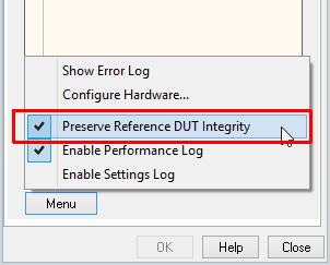
Note
Not all modifications are allowed in case reference DUTs are present. All changes to the EXD test sequence which cause data inconsistency (adding/removing measures) will block the test start. If the limits are not based on reference units, you will be asked to recalculate only.
Limit Setup for Single Value Results#
The available parameters of the limit setup matrix for single value measures (value steps) are
listed and explained here.
The general format (matrix line entry) is:
' <Measure name (step label)> | <Limit calculation mode> | <opt1:Limit parameter min> | <opt2:Limit parameter max> | <opt3:Cpk-PoolSize>} | <opt3:Cpk-Limit> | <opt3:Ppk-Limit> | <opt3:Cpk/Ppk-PassedOnly> '
The number and order of lines/entries can be chosen arbitrary. Only the measure name/label has to
equal the corresponding value step in the EXD Step Sequence.
Lines starting with “//” (after the quotation mark) are ignored and can be used for comments or to
deactivate entries. No upper/lower limit is applied if the min/max parameter is left empty. If no
entry is specified at all, the corresponding measure will be passive.
Please also refer to Working with Limits and the task specification S31 QC – External Devices.
Name#
Here, the measure name is specified according to the corresponding measurement step (value) in the
EXD Step Sequence. This is required to relate the limit setting to the external measurement data.
Limit Calculation Mode#
The limit calculation mode is specified by this parameter. It determines how the limits are calculated from the reference measurements. Four modes are available, represented by the following tokens:
relativestatisticabsoluteshift
Please refer to Limit Setup - Single Values for further details.
Limit Parameter min & max#
These two parameters set up the upper and lower limit calculation quantitatively, according to the limit calculation mode. No upper/lower limit is applied if left empty. Please refer to the table in section Limit Setup - Single Values for details about the limit parameters.
Cpk/Ppk Parameters#
To activate and set up the Cpk/Ppk online statistics for single value measures these four parameters are required:
Cpk-PoolsizeCpk-LimitPpk-LimitCpk/Ppk-PassedOnly
The Cpk/Ppk process analysis is optional and will only be activated if the parameters are specified for the corresponding measure in the Limit setup.
For further information about the parameters and online statistics please refer to the Ppk / Cpk.
Imported Reference Data – Single Measures#
Single value measure type supports importing external reference DUTs or respectively mean value (Imported Measured Data) and corresponding standard deviation (Imported Standard Deviation). The parameter format closely follows the standard format as specified in section Limit Import in QC User Manual. The data is interpreted differently, however.
Imported Reference DUTs#
The first column of parameter Imported Measured Data represents the step ID, each line
corresponds to an individual measurement step in The EXD Step Sequence. The step ID may be
chosen freely, but it should correspond to (value) step number in the test sequence.
- Example
valueImportMeas = [
1   10     9     11
2   50     48    53
3   0.2    0.1   0.3];
Mean Value and Standard Deviation#
The parameters Imported Measured Data (mean value) and Imported Standard Deviation (standard deviation) follow the format introduced in previous section. However, the column number is restricted to two.
- Example
valueImportMeas = [
1   9
2   48
3   0.1];

valueImportStDev = [
1   0.3
2   2.32
3   0.0013];
Limit Setup for Read Strings#
The available parameters of the limit setup matrix for string messages (read steps) are listed and
explained here. The general format (matrix line entry) is:
' <Label> | <Mode> | <Target string> '
The number and order of lines/entries can be chosen arbitrarily. Only the step label has to equal
the corresponding read step in the EXD Step Sequence.
Lines starting with “//” (after the quotation mark) are ignored and can be used for comments or to
deactivate entries. Missing entries will deactivate the check for the corresponding measure (passive).
Please also refer to Working with Limits and the task specification S31 QC – External Devices.
Name#
Here the step label/name is specified according to the corresponding step (read) in the EXD Step Sequence.
Mode#
This parameter determines the mode of string comparison between the message read and the target string:
equal
notEqual
Target string#
The target string defines the character string to be compared with the read message.
Settings and Limit Import#
The EXD task supports general parameter and limit import based on parameter text files according to QC User Manual sections Limit Import and Parameter Import. There you may also find details on general parameter and file format.
Setup Parameters#
All available task properties of the EXD may be imported from an external parameter file. The following table lists the IDs of all available parameters and the corresponding English text labels as shown in the user interface. Please use the IDs only for import.
- Error mode
- Type: string
Parameter Name (EN) |
ID |
|---|---|
Error mode |
|
|
|
|
|
|
|
|
|
- Error handling
- Type: string
Parameter Name (EN) |
ID |
|---|---|
Error handling |
|
|
|
|
|
|
|
- Digital out (amp check)
- Type: binary matrix [8x2]
Parameter Name (EN) |
ID |
|---|---|
Digital out (amp check) |
|
- Mode (EXD Sequence)
- Type: string
Parameter Name (EN) |
ID |
|---|---|
Mode |
|
|
|
|
|
- Select Preset
- Type: string
Parameter Name (EN) |
ID |
|---|---|
Select Preset |
|
|
|
|
|
- Step Sequence
- String vector [nx1]
Parameter Name (EN) |
ID |
|---|---|
Step Sequence |
|
- Bus mode
- Type: string
Parameter Name (EN) |
ID |
|---|---|
Bus mode |
|
|
|
|
|
|
|
- Termination character
- Type: string
Parameter Name (EN) |
ID |
|---|---|
Termination character |
|
|
|
|
|
|
|
- EOI termination
- Type: Bool
Parameter Name (EN) |
ID |
|---|---|
EOI termination |
|
- Status handling
- Type: Bool
Parameter Name (EN) |
ID |
|---|---|
Status handling |
|
- Init Controller
- Type: string
Parameter Name (EN) |
ID |
|---|---|
Init Controller |
|
|
|
|
|
- COM port
- Type: Integer
Parameter Name (EN) |
ID |
|---|---|
COM port |
|
- Read timeout
- Type: numerical value
Parameter Name (EN) |
ID |
|---|---|
Read timeout |
|
- Customizations
- Type: Bool
Parameter Name (EN) |
ID |
|---|---|
Customizations |
|
- Parameters
- Type: string matrix
Parameter Name (EN) |
ID |
|---|---|
Parameters |
|
- Setup
- Type: string matrix
Parameter Name (EN) |
ID |
|---|---|
Setup |
|
Limit and Limit Settings#
The EXD supports full import of limit parameters and partly import of external reference DUTs. For details about parameter format refer to section Task Parameters.
Limit Parameters#
In contrast to standard measurement tasks like SPL or IMP, all limit settings of the EXD are defined in a single string matrix. Therefore, all limits settings are available for import according to the limit parameter format as specified in section Task Parameters.
- Limit Parameters
- Type: String vector [N x 1]
Parameter Name (EN) |
ID |
|---|---|
Single Values - Limit Setup |
|
Read Strings - Limit Setup |
|
External Reference DUTs or Mean Value and Standard Deviation#
The import of external reference DUTs or respectively mean value and standard deviation is only supported for single value measure type:
- Limit Parameters
- Type: double matrix [N x 2]
Parameter Name (EN) |
ID |
|---|---|
Single Values - Imported Measured Data |
|
Read Strings - Imported Standard Deviation |
|
Troubleshooting#
This section discusses a selection of probable errors and warnings that may occur using the EXD Task.
Warning Messages#
Here, the warning messages generated by the EXD Task are listed and discussed.
- “Prologix GPIB-USB Controller version is below 6.9. Full functionality not guaranteed”
During the initialization of the GPIB controller the hardware ID is queried. The EXD Task supports Prologix GPIB-USB controller from version 6.9. Older versions may cause problems due to incompatibility or differing command sets.
- “Connected GPIB controller unknown. Functionality not guaranteed”
In this case the connected controller could not be identified as Prologix GPIB-USB controller by the serial string. Other bus controllers are currently not supported by the EXD Task.
- “One or more limit/target definitions missing, corresponding measures will be passive”
This notification indicates that limits have not been defined for all available measures as defined in the Test sequence. The missing ones will be measured but not tested against limits.
- “Multiple pairable devices found. Connecting to first available.”
This warning is displayed when multiple pairable devices are found (in auto pairing mode) or multi matches for a specified friendly name are found. The EXD will pick the first device in the list.
- “No pairable device found. Connecting to a previously paired device.”
No device that matches the defined name in pairing mode has been found. A previously connected (remembered) device is reconnected.
Error Messages#
Here a selection of error messages generated by the EXD Task is listed and discussed.
Property Page Errors#
GPIB is deactivated#
This message appears in the property page if the EXD Step Sequence contains GPIB steps while GPIB is deactivated. Please select the bus mode according to the connected devices or remove the regarding lines from the test sequence.
General Interface Errors (GPIB, Bluetooth)#
No controller/interface identified#
No GPIB or Bluetooth interface was found during auto search or at the specified serial port (no valid response). Check that the interface is connected and installed properly.
Check the USB connection between controller and PC. Try to disconnect and reconnect the cable to reset the controller, which might be in an error state.
Check Windows device manager for USB serial port. The assigned COM number should be below 20. In this case reassign the COM number or set it manually in the EXD Task. If the device does not exist install the USB device driver provided with the Qc setup files.
Also find more information in section Setting Up the Bluetooth Interface.
Error: Failed to open COM<num> (system error code <num>)#
This message may occur if the virtual COM number of your GPIB controller or Bluetooth interface is specified manually. In this case either specified number does not correspond to the port that is assigned to the controller or the controller is not installed or connected properly. Please follow the instructions according to the error above in this case.
Error: Reading/Writing virtual serial port failed (system error code <num>)#
In this case the access to the virtual serial port of the GPIB controller was denied or the port is not available. Please refer to the Windows System Error Code for probable causes.
Another application blocking the port is very common (code 5). Multiple instances of dB Lab or GPIB configurator might interfere and have to be closed.
If the wrong port number is selected the error code would be “2”.
GPIB Controller Errors#
Error: automatic controller initialization failed * controller not found or not responding#
If the virtual COM number of the GPIB controller is determined automatically (property: Init controller - automatic) all available ports from 1 to 20 are scanned for Prologix GPIB-USB controller.
This error occurs in case no controller was found or the controller is not responding properly.
Check the USB connection between controller and PC. Try to disconnect and reconnect the cable to reset the controller, which might be in an erroneous state.
Check Windows device manager for USB serial port. The assigned COM number should be below 20. In this case reassign the COM number or set it manually in the EXD Task. If device does not exist install the USB device driver provided by Prologix.
Alternatively use Prologix GPIB configurator to check if the controller is connected and responding.
Timeout occurred while reading GPIB controller#
This message indicates a timeout while reading the output buffer of the GPIB controller.
Error: No GPIB controller identified (response timeout)#
See above
Unable to set GPIB device address <addr>#
The GPIB controller has returned an error while setting the GPIB address of the target device. Try to reconnect the controller if the error is persistent.
GPIB communication errors#
GPIB device at address <addr> could not be initialized: <error>#
This error may occur during GPIB device initialization after starting a measurement. For details stick to the error message stated.
Please check that your GPIB device is turned on and properly connected to the controller. Also check the device remote configuration. GPIB remote control has to be activated and the unique bus address must be set correctly to correspond with the settings in the EXD Step Sequence.
Also check if the device complies with the GPIB standard, which is selected in the task property Bus mode. In case of conflicts, deactivate property Status handling or switch back to IEEE 488.1 mode.
Refer to Prologix GPIB Configurator for detailed troubleshooting using the specific console application.
Timeout occurred while reading GPIB device#
A timeout while reading the output buffer of a GPIB device implies that there is no data to read.
Check if the GPIB command sent contains a query command.
Also check if status handling or respectively IEEE 488.2 is supported by the device, if selected.
Timeout occurred while reading GPIB device status#
This error may only occur if Status handling is activated. After sending a configuration or query command to GPIB device its status is polled in a loop until the operation complete flag (OPC) or respectively the message available (MAV) flag is set.
Please check if your device is IEEE 488.2 compliant and supports status handling according to the standard.
Also check your GPIB command in the EXD Step Sequence, which is sent to the device. Value or read steps require a query command. Otherwise the output buffer of the device will stay empty.
GPIB Device Status Errors & Warnings#
This category of errors and warnings is originated in the status system of the connected GPIB devices. Therefore, they are only available if the devices are IEEE 488.2 compliant and Status handling is activated (Configuration Parameters).
The standardized GPIB status reporting system implies several status registers that are set up during initialization and read during execution by the EXD Task automatically. Please refer to the task’s specification S31 QC – External Devices for further details about the internal GPIB status handling of the EXD Task.
Most of the register states (specific bit is set) correspond to a defined standard status, which is device independent. However, some device specific states may be defined by the manufacturer. Those register states may be deciphered using the devices programming manual. In this case the resulting error will only indicate the concerning register and the bits (e.g.: “Questionable data: Status register bit 9”). Additional sub-registers (optional) may also provide more information. Those registers are excluded from the status handling of the EXD task.
Nevertheless, all general errors and warnings are interpreted by the EXD task according to the industry standard.
Standard event register (errors):
Query error
Device error
Execution error
Command error
Power on (device has been power cycled)
Questionable data register (warnings):
Voltage
Current
Time
Power
Temperature
Frequency
Phase
Modulation
Calibration
For error and warning causes and remedies please refer to device’s manual or read the error queue of the device if available.
Bluetooth Pairing Errors#
No previous Bluetooth device information retrieved. Please pair first.#
When using multiple EXD steps or even operations with the same device, it is only required to pair once in the beginning. The device information is passed to the other EXD instances by using the option Select Device – Previously Paired. The error is displayed when no information is available. Make sure that an actual pairing step is executed before and that no un-pairing has been triggered before this step.
No device connected - please pair first#
This error is triggered when trying to change Bluetooth settings without explicitly pairing a device first or if the previously paired device is not connected anymore. Activate Pair Device.
No matching device found for requested friendly name#
For Bluetooth device pairing based on friendly name a device scan is performed first. If no pairable device with matching name is found, this error will be displayed. Make sure that your DUT is activated and in pairing mode. Also check for spelling errors and case.
No pairable device found#
Using mode Pair Device – Auto any pairable device will be paired and connected. If no device was found at all, this error is triggered. Make sure that your DUT is activated and in pairing mode.
Pairing with device “…” failed#
When this error is shown a device according to the specified filter criteria was found but could not be paired. The reason can be a timeout or a functional error. Check that the DUT is still switched on and in pairing mode.
Sound Device Handling Errors#
Waiting for sound device “…” timed out.#
The default playback/capture device does not correspond to the specified device name. Check that the name has been spelled correctly (case sensitive!) and that the device is actually paired or connected. Use the Enumerate function button to list all available devices and to see which devices are selected as default sound devices.
In some cases (e.g. if connected before), a freshly connected device is not selected as default sound device automatically. in this case set it manually in the Windows Sound configuration dialog or in the task bar.
Windows Default (Voice) Playback/Capture device must be selected as output device in this QC operation.#
In order to check the default sound device’s name, it is required to actually use it as playback or capture device in this QC operation. Refer to Playback/Capture Device Setup for Bluetooth & Sound Device Application for more information.
