
Micro Speaker Clamping#
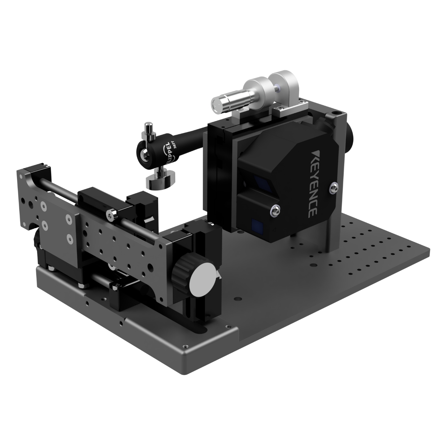
Overview#
Can be mounted to “Micro Speaker Clamping” as compact speaker measurement platform with DUT in vertical position.
Can also be mounted to Vacuum Stand for horizontal placement of the DUT in the Vacuum Chamber or for other horizontal measurements like on the Scanning Vibrometer.
Type 1: Micro Speaker Clamping#
Compact, transportable, multifunctional transducer measurement platform
For Micro Speaker, Headphones, Tweeter and any transducer up to 100 g
Solid but adjustable mounting of laser displacement sensors and measurement microphones
Different DUT clamping options available
Can be easily modified to own applications, many additional mounting threads are present
Can be used with a wide range of laser sensors
Optimized for KEYENCE LK-H052
Horizontal laser measurement position on the DUT can be continuously fine positioned by manual linear adjustment.
Vertical laser measurement position on the DUT can be continuously positioned on the laser mounting slider
Distance between DUT and laser sensor can be fine adjusted by available TRANSLATION STAGE with MICROMETER SCREW or in 10 mm steps
Type 2: Vacuum Stand#
Can be modified to a Vacuum Stand to fix loudspeakers during measurement and adjust its height close to the glass cover of the vacuum chamber
Can be used to fix loudspeakers at the SCN turntable during Scanning Vibrometer measurements or other RnD measurement tasks
Micro Speaker Clamping#
List of screws#
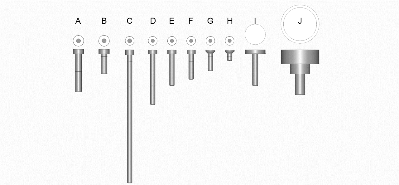
A: M5x30 Allen screw 2 pc.
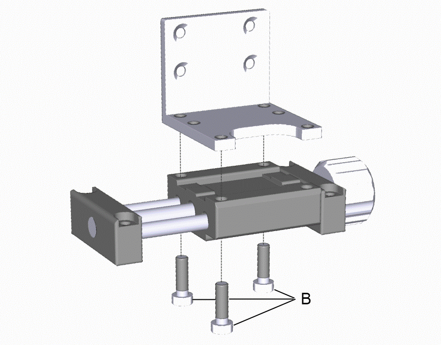
B: M5x18 Allen screw 3 pc.
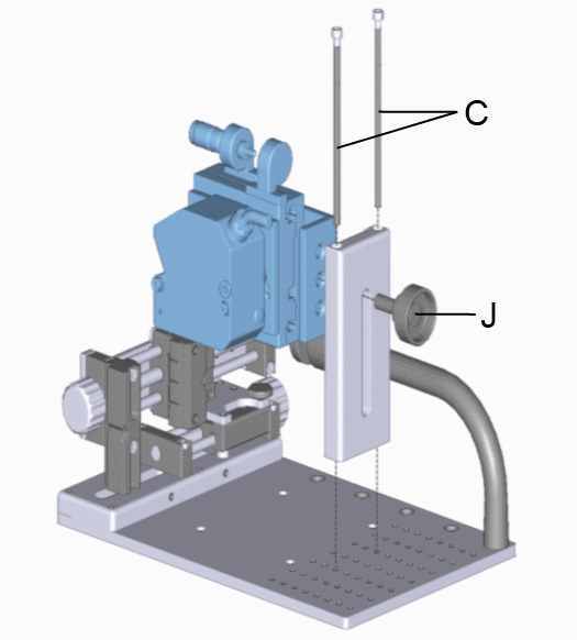
C: M4x100 Allen screw 2 pc.
D: M4x40 Allen screw 2 pc.
E: M4x25 Allen screw 4 pc.
F: M4x20 Allen screw 2 pc.
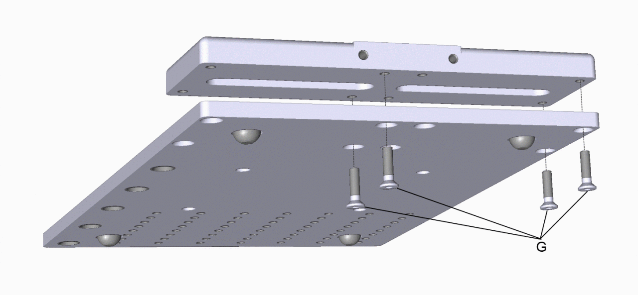
G: M4x16 Allen counter sunk screw 4 pc.
H: M4x8 Allen counter sunk screw 4 pc.
I: M5x25 plastic hand screw 1 pc.
J: M8x16 hand screw 1 pc.
K: M10x20 hand screw 1 pc. (not shown)
Mounting instructions#
Follow the instructions step by step to mount the Micro Speaker Clamping.
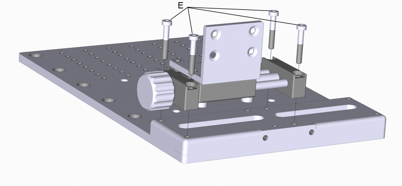
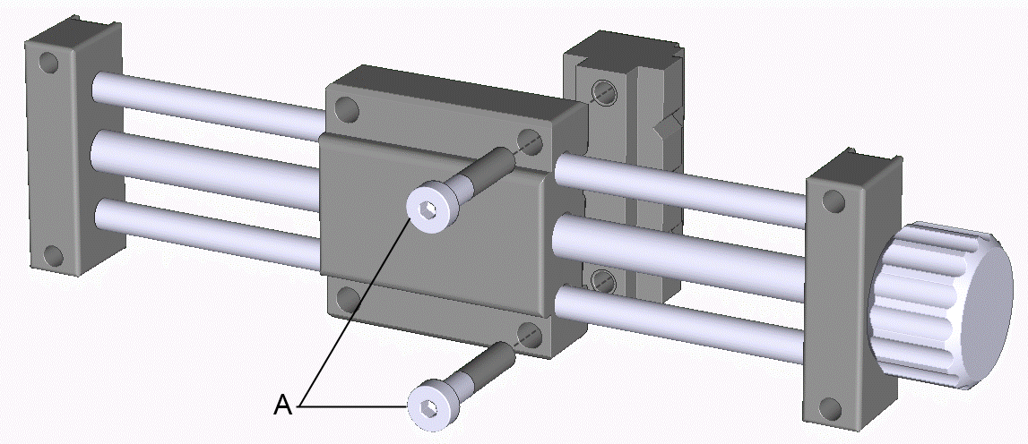
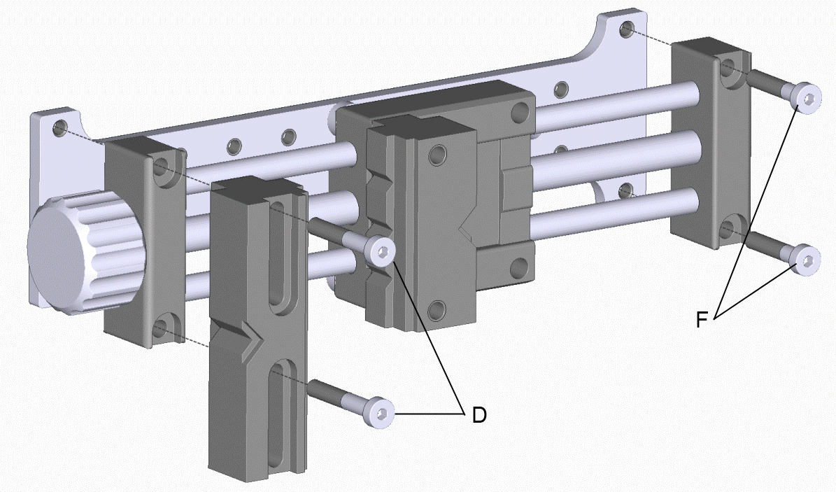
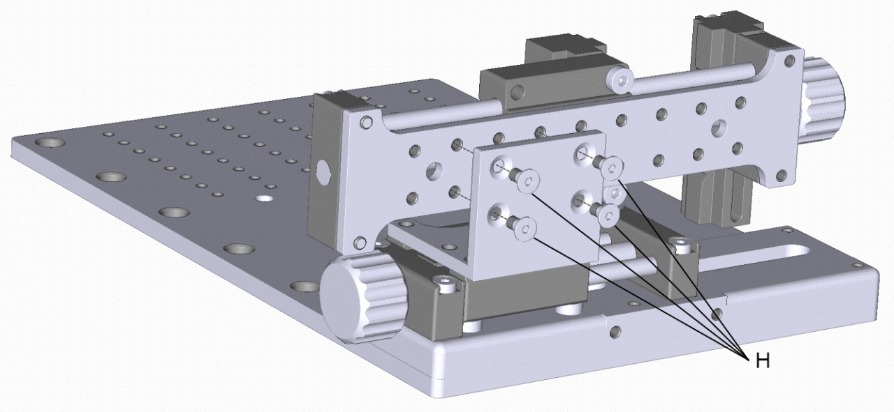
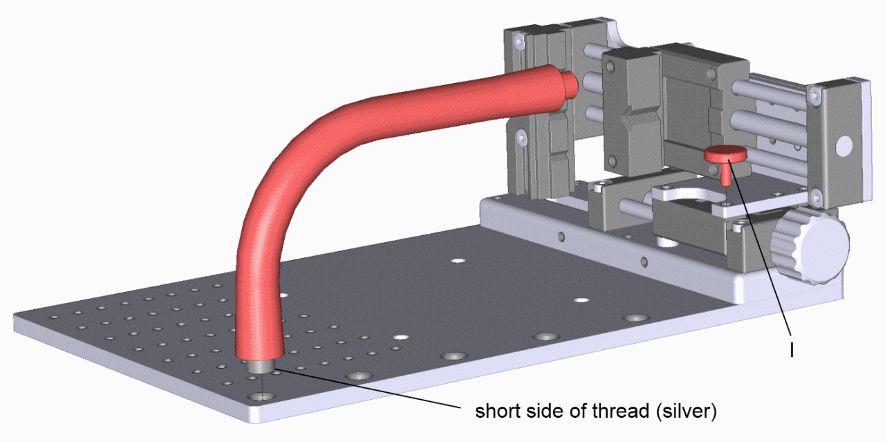
Type I of the goose neck has 3/8” outer threads on both sides. Mount shorter silver side to the ground plate.
Type II of the goose neck has 3/8” outer thread at the side which should be mounted with a washer to the ground plate and a 3/8” inner thead at the side to the mic clamp. An adapter from 3/8” outer thread to 1/4” outer thread to mount the ball joint is included.
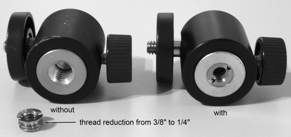
Type I of the ball joint has 3/8” inner thread. The thread reduction has to removed before the ball joint can be screwed on the type I goose neck.
Type II of the ball joint has 1/4” inner thread. It may directly be mounted at the Type II goose neck with its 1/4” outer thread.
Laser Accuracy Check & Laser Calibration#
By using the Translations Stage with Vernier Micrometer#
To adjust the distance between target and laser sensor at the Micro Speaker Clamping the usage of the Translation Stage with Vernier Micrometer is always recommended for all laser types. The Micro Speaker clamping can be used with all Klippel provided laser types but the usage of the Keyence LK-G32, LK-G82 or LK-H52 is recommended.
The smaller mounting bracket has a white matt calibration target sticker on it.
Point the laser beam to the calibration target
Follow the instructions in the separate Hardware Manual
By using the calibration step target from the Small or Pro Driver Stand#
An alternative method to adjust the distance between target and laser sensor at the Micro Speaker Clamping is the usage of the calibration step target from the Small or Pro Driver Stand. This method should only be used for long travel laser sensors.
Fix the calibration step target in parallel to the mounting bracket.
Point the laser beam to the middle step of the calibration target.
Follow the instructions in the separate Hardware Manual
Turn brackets#
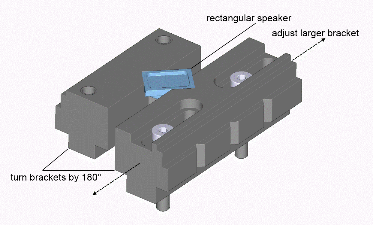
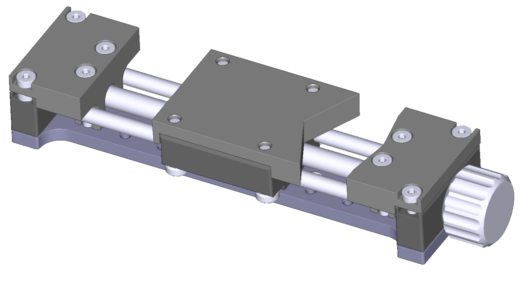
You can turn the brackets by 180° and adjust the larger bracket to mount a rectangular speaker!
Bracket displacement#
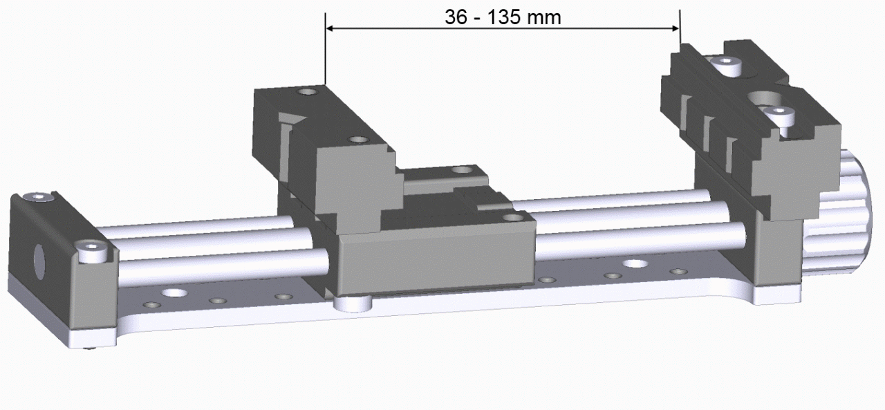
You can displace the small bracket to enlarge the clampingarea!
Usage at the Vacuum Chamber#
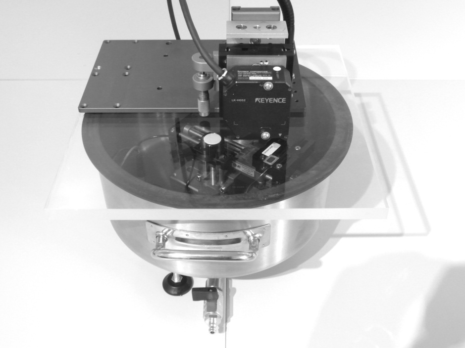
The Vacuum Stand can be used to adjust the distance between DUT inside the Vacuum Chamber and the glass plate (Laser Sensor outside).
The platform from the Micro Speaker Clamping can be used to place the laser sensor above the DUT at the Vacuum Chamber.
Laser Accuracy Check & Laser Calibration#
The Vacuum Stand offers an additional method for the Laser Accuracy Check and Laser Calibration if a Klippel Scanning Vibrometer is available.
In the SCN software a Direct Motor Control tool is added to shift the distance between target and laser sensor in absolute values. It can be accessed inside the SCN software by clicking Tools / Direct Motor Control or directly with Function Key F5.
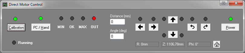
Alternatively both methods described in the chapter Micro Speaker Clamping Laser Accuracy Check & Laser Calibration can be used.
Additional Instructions#
Bracket Exchange Instruction#
Bill of material#
Position |
Quantity |
Name |
Revision |
|---|---|---|---|
1 |
1 |
All-purpose bracket 0° |
1.1.6 |
2 |
1 |
All-purpose bracket 160° |
1.1.6 |
3 |
1 |
All-purpose bracket for carriage |
1.1.6 |
4 |
4 |
Screw M5x18 DIN 7984 |
|
5 |
8 |
Screw M5x18 DIN 7984 |
Position |
Quantity |
Name |
Revision |
|---|---|---|---|
1 |
1 |
All-purpose bracket 0° |
1.1.6 |
2 |
1 |
All-purpose bracket 160° |
1.1.6 |
3 |
1 |
All-purpose bracket for carriage |
1.1.6 |
4 |
4 |
Screw M5x18 DIN 7984 |
|
5 |
8 |
Screw M4x25 DIN 7984 |
All-purpose bracket set is included in Microspeaker Clamping and Vacuum Stand Rev. >= 1.2.0.
For earlier revisions the set is available as accessory.
Unmount microspeaker brackets#
Unmount fixed original microspeaker clamping bracket
Use allen key 2,5 mm
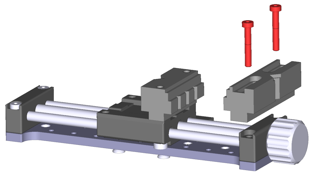
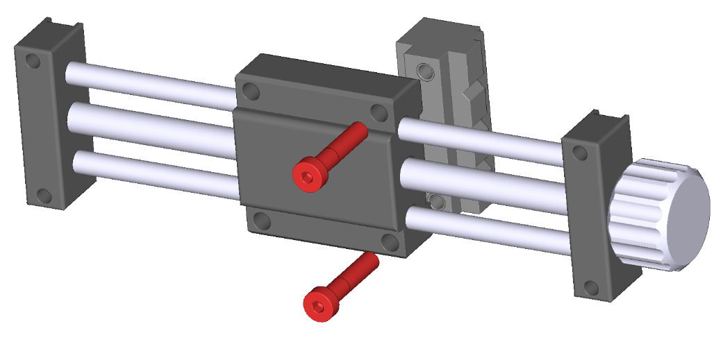
Unmount carriage
Use allen key 2,5 mm
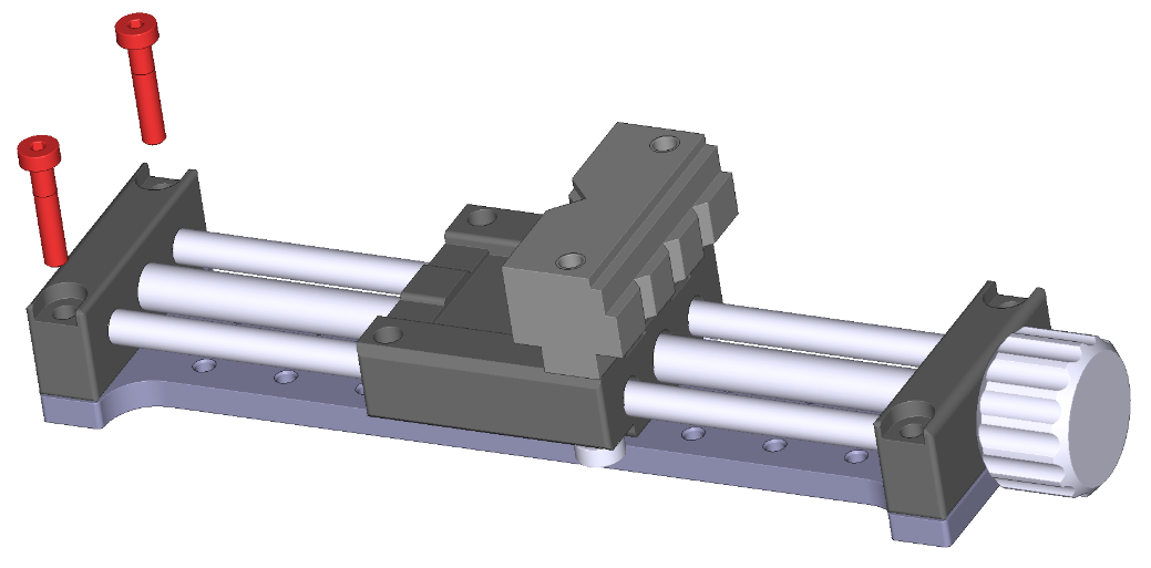
Unmount adjustable original microspeaker clamping bracket
Use allen key 3 mm
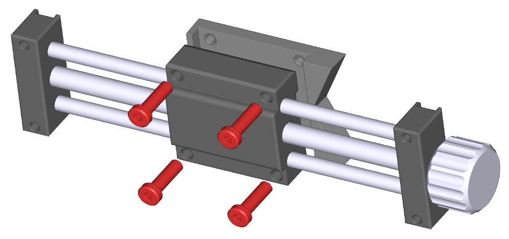
Mount all-purpose brackets#
Fasten all-purpose bracket for carriage in place by 4 screws DIN 7984 M5x18
Use allen key 3 mm
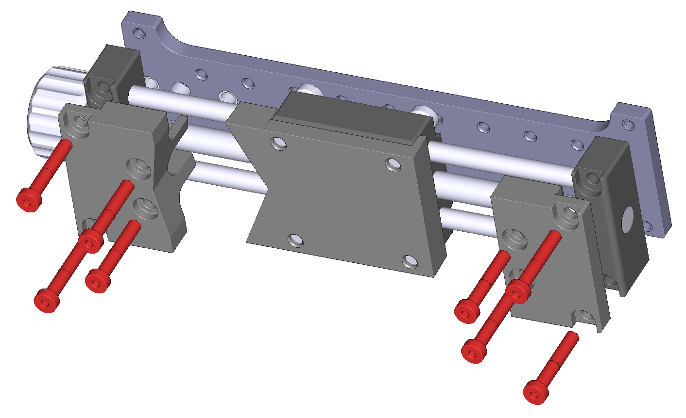
Fasten all-purpose bracket 0° and all-purpose bracket 160° in place by 4 screws DIN 7984 M4x25 each
Use allen key 2,5 mm
The direction of all-purpose bracket 0° and all-purpose bracket 160° depends on your application (both directions are possible)
Maintenance Instructions#
Cleaning#
Do not use any detergent for cleaning Hardware unit. Do not use wet cleaning material. The Hardware unit is not protected against wet environments. Please ensure dry conditions and operation within the allowed temperature range.
Service#
All mechanical parts of the Micro Speaker Clamping are lubrication free and need no periodical service.
The bearing clearance could be adjusted with an 2 mm hex wrench at the end of the guiding spindle.
