
NFS – Near Field Scanner - Assembly#
Safety Instructions#
Carefully read all safety instructions. KLIPPEL will not be responsible for any harm or damage resulting from disregard of the Safety instructions.
Warning
Assembly of the device must be done by skilled personnel
The personnel must fully understand the instructions given in the Assembly instructions. Through their qualification they must be familiar with risks mentioned in the instructions and avoid any danger in a thoughtful manner.
Warning
Follow the exact instructions Ensure to follow every detail in this instruction. All Assembly steps are mandatory for proper operation of the device.
Warning
Proper Floor mounting
Ensure, that the Near Field Scanner is properly mounted to the floor on all 4 sides.
Warning
Do not modify the machine.
Use original cables, power supply and assembly parts only. Do not modify or repair KLIPPEL hardware or accessories without explicit instruction by KLIPPEL!
Warning
Comply with the specified weight limits and requirements to the setup location
Set-up area must be in a dry and clean indoor condition.
The device must be set up in a separate room, or separated area, which can be closed to unintended access by personnel. If access cannot be restricted by a separate room, a protective device (e.g. fence) must be installed around the measurement device. (Risk of tripping and crushing)
The setup location of the device must be properly illuminated to at least 300lx. (Risk of tripping)
A sound pressure level of 80dB should not be exceed at any nearby work area.
Introduction#
Overview of NFS assembly steps#
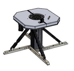
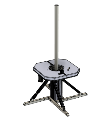
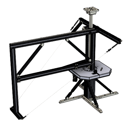
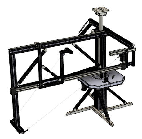
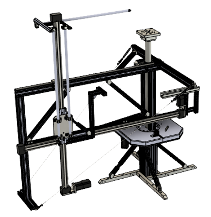
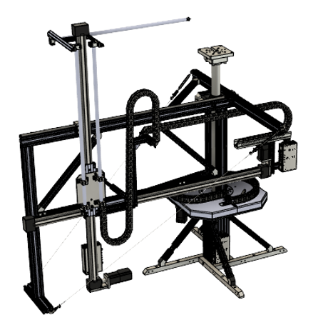
General Assembly hints#
Preliminary remarks#
Unpack all packets and boxes before starting with the assembly to get an overview.
Pay special attention to the details of the aluminum profiles in packet 2. The profiles are identified in this manual by length and features like hole-count. Some profiles have identical lengths and may appear identical on first sight, but still differ in small details.
Leave all parts in their bags as long as you don’t need them! This will make it easier to find the parts you need at the specific step.
The numbering of the bags is primarily based on the assembly order.
The open face ends of all aluminum profiles may have sharp edges. Be careful during the assembly procedure to avoid injuries before all open face ends are covered by plastic caps!
Use only the provided manual tools unless specified otherwise. Do not overtighten screws!
How T-nuts are used#
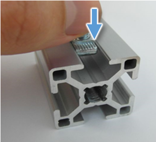
T-nuts are an important connecting tool for the aluminum strut profiles of the Near Field Scanner.
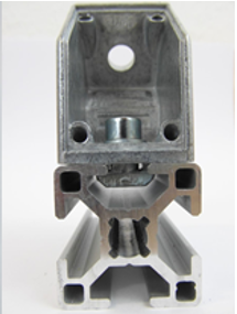
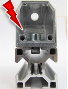
They are very handy compared to normal slot nuts because it is not necessary to insert them into the end of the slot. Instead, they can be inserted at any place along the slot. By tightening the screw, the T-nut turns and locks inside the slot as shown in the picture below. The example on the right side shows what happens if the T-nut is not inserted correctly into the slot. In this case the T-nut is not able to turn within the slot.
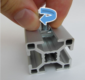
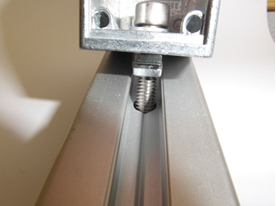
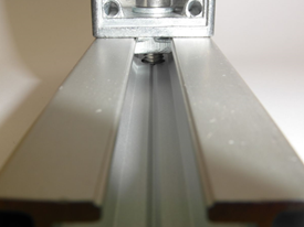
Some joint locations are predefined by drilled holes in the profiles to simplify exact positioning of the joint. At these locations, longer screws are used, that reach through the T-nut into the hole.
How screws are distinguished#
Cylinder head#
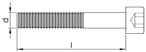
DIN 912 / ISO 4762 (In this manual just referenced as screw)
Low-profile cylinder head#
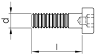
DIN 6912
Countersunk head#
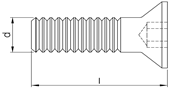
DIN 7991 / ISO 10642
Half round head with collar#
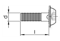
ISO 7380-2
- Notation example
- M6x40 means:
thread diameter d = 6mm
length l = 40 mm.
Note
Note that the length of countersunk head screws is measured over the whole screw including the head!
Use of Assembly Paste#
Due to occurring seizing between screws and components we recommend to use the assembly paste provided. This will facilitate the partial disassembly of the NFS at a later date, e.g. for moving it to another location. Apply assembly paste on every countersunk head screw before inserting it.
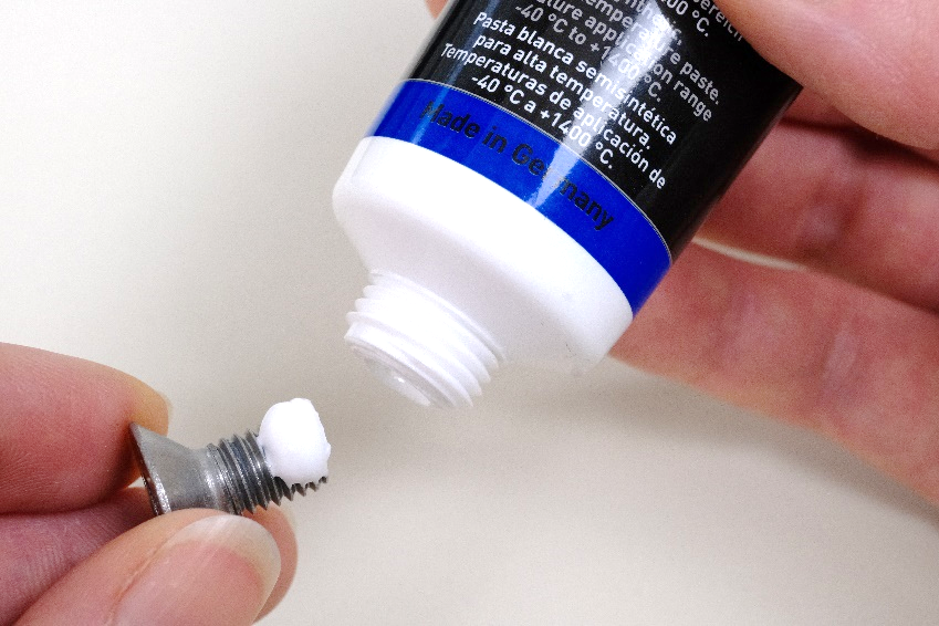
Squeeze a small heap of paste onto one side of the lowest turns of the screw as shown in the picture. Screw it in as usual.
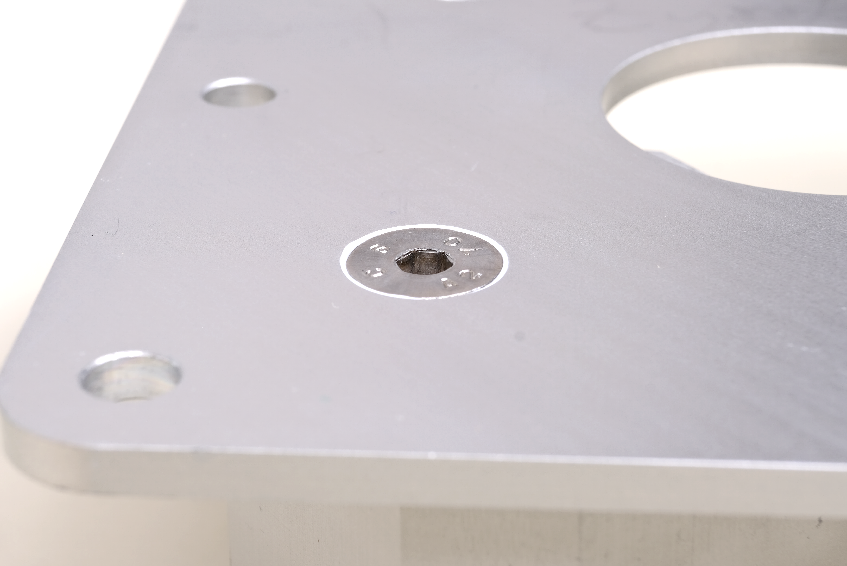
You have used the right amount if a little paste is pressed out from under the screw’s head when tightening. Remove the excess with a dry cloth.
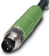
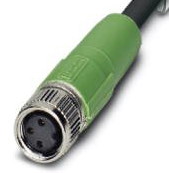
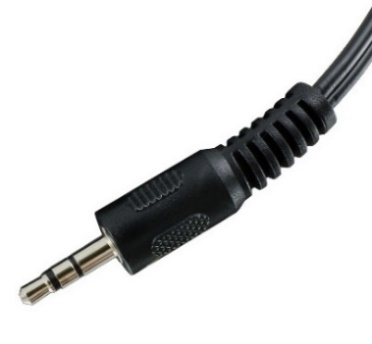
How cable plugs are distinguished#
XLR#
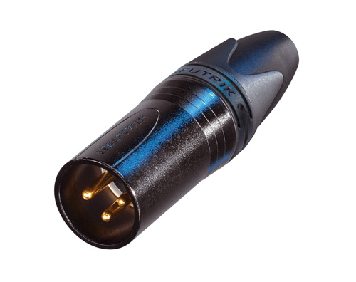
- plug / male
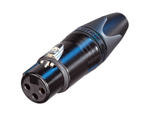
- socket / female
EtherCON#
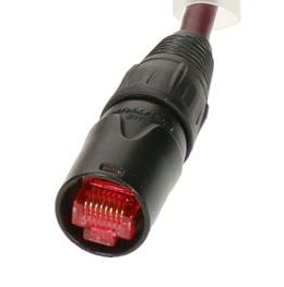
M12#
- plug / male
- socket / female
3.5mm phone jack (TRS)#
Packing Structure#
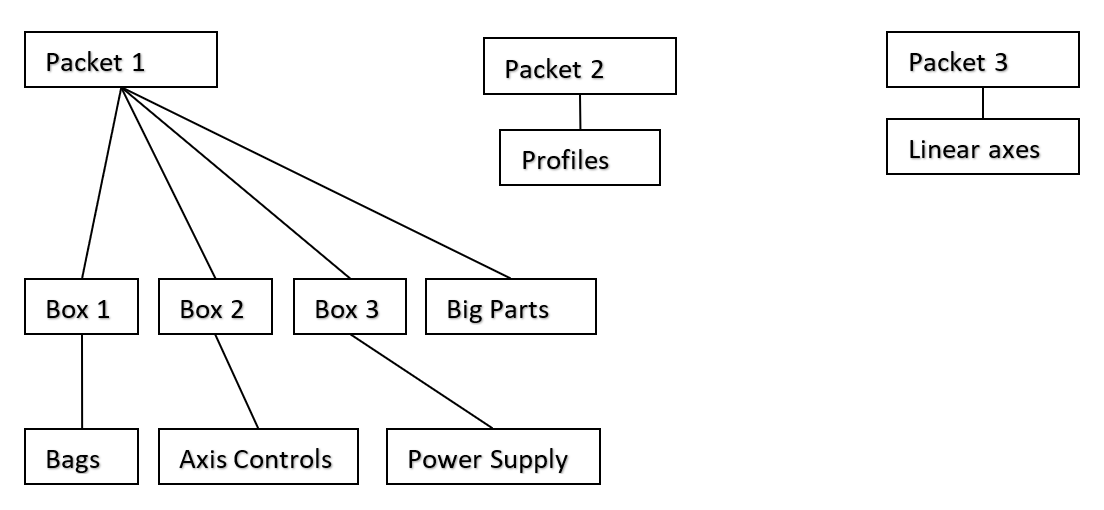
Parts Lists and Assembly Steps#
This manual is structured in chapters which chronologically describe the assembly steps of each major subcomponent of the NFS.
Each assembly chapter is led by a parts list which lists the parts used in the assembly of the chapter and the respective location of this part in the packing-structure. Each part in this assembly list is identified by an alphanumerical designator by which it is referenced in the following assembly steps. The designators reset for each assembly chapter and are only unique in the respective chapter.
Tools#
Tools provided with the NFS#
The tools provided with the NFS are based on ¼” square drive shaft tools, bits as well as extensions and adapters. Combination of the wrench or screwdriver handle with the different bits and extensions enables optimal access to all screws during the NFS assembly.
Torque wrench ¼”#

Controlled high torque application for larger screws
Screwdriver handle ¼”#

Low torque application for smaller screws
Extension ¼”

Universal joint ¼”#
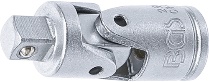
Adapter to enable access to obstructed screws
Allen socket bits ¼”#
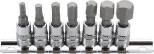
(H2.5, H3, H4, H5, H6, H7, H8, H10, H12)
Adapter for hex-bits ¼”#
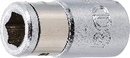
apter to mount extra-long All bits
Extra-long Allen bits#

(H4L, H5L, H6L)
Bits to access screws in narrow spaces
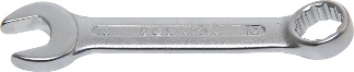
Combination wrench (size 13)#
Units: 2
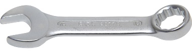
Combination wrench (size 19)#
Spirit level#

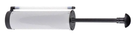
Blow out pump#
Additional tools needed#
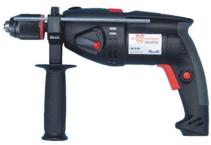
Power drill#
12mm or ½” Drill bit#

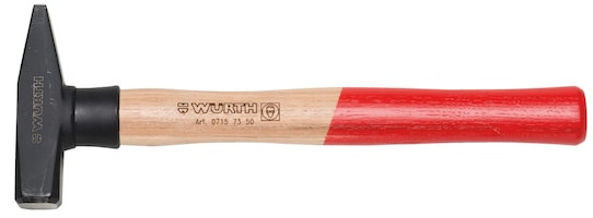
Hammer#
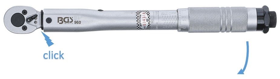
How the torque wrench is used#
Unlock the counter screw of the wrench
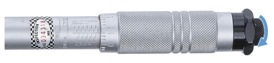
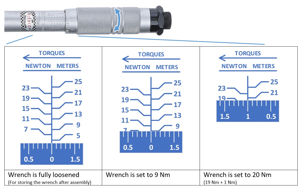
Adjust wrench to required torque
Lock the counter screw of the wrench
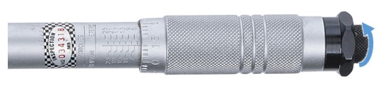
Pull on the wrench and turn screw until the wrench clicks
Stop pulling after the click. Do not turn the screw further.
Required torque settings#
Some screws and fasteners of the NFS require the application of a specific torque during the assembly. Those assembly steps arm marked with the symbol Nm and a torque indication.
- Example:

All assembly steps without a specific torque indication are less critical. Refer to following table as a guideline on how much torque should be applied during the assembly, indicated by the size of the screw or fastener:
Recommended Torque and Tool for Screws#
- M3
- Torque: 1 NmTool: Screwdriver handle
- M4
- Torque: 2 NmTool: Screwdriver handle
- M5
- Torque: 4 NmTool: Screwdriver handle
- M6
- Torque: 8 NmTool: Torque wrench
- M8
- Torque: 16 NmTool: Torque wrench
- M10
- Torque: 20 NmTool: Torque wrench
Screw Size |
Recommended Torque |
Recommended Tool |
|---|---|---|
M3 |
1 Nm |
Screwdriver handle |
M4 |
2 Nm |
Screwdriver handle |
M5 |
4 Nm |
Screwdriver handle |
M6 |
8 Nm |
Torque wrench |
M8 |
16 Nm |
Torque wrench |
M10 |
20 Nm |
Torque wrench |
Warning
Do not overtighten screws! The torque wrench can easily apply high torque due to leverage and can damage small screws. Always use the screwdriver handle for smaller screws!
Setting up the Hardware#
Setup area selection#
Room and Location Specs#
Before setting up the NFS hardware, choose an appropriate room and location which meets following specs:
Floor material which can be drilled to mount the NFS to the floor (see assembly step 15)
Lockable door to prevent unintended access during measurements
Sufficient space of at least 3 m x 3 m.
Example setup#
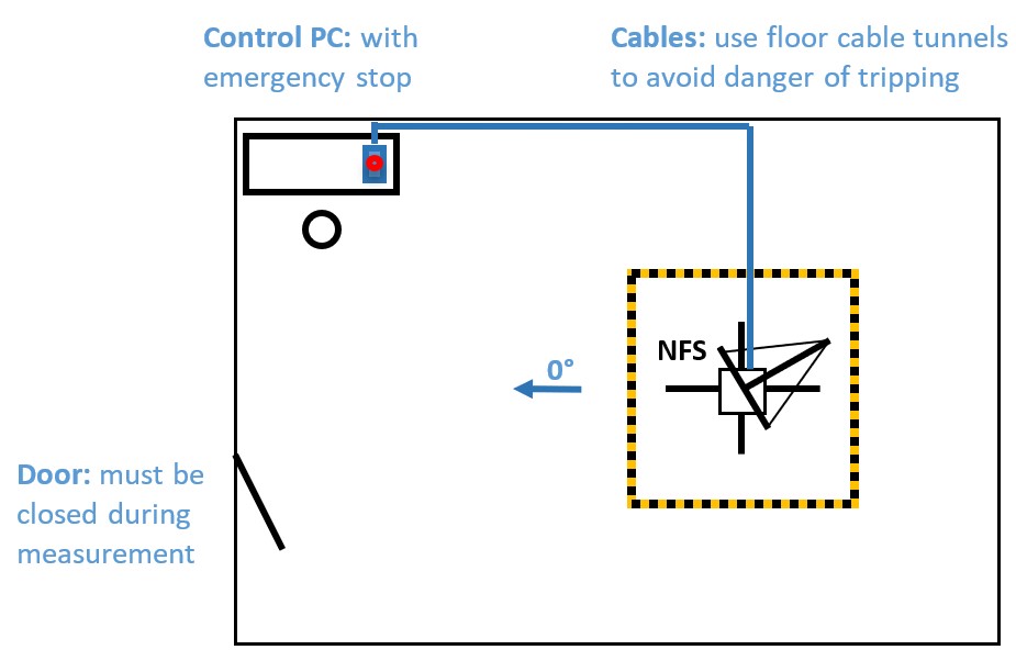
Setup recommendations#
Place the NFS at a central position in the room with maximum distance to all neighboring walls
Orient the 0° index of the NFS towards the wall with the maximum distance in rectangular or otherwise irregular shaped rooms
Deploy floor cable tunnels to reduce the danger of tripping over cables between Control PC and NFS
Table assembly#
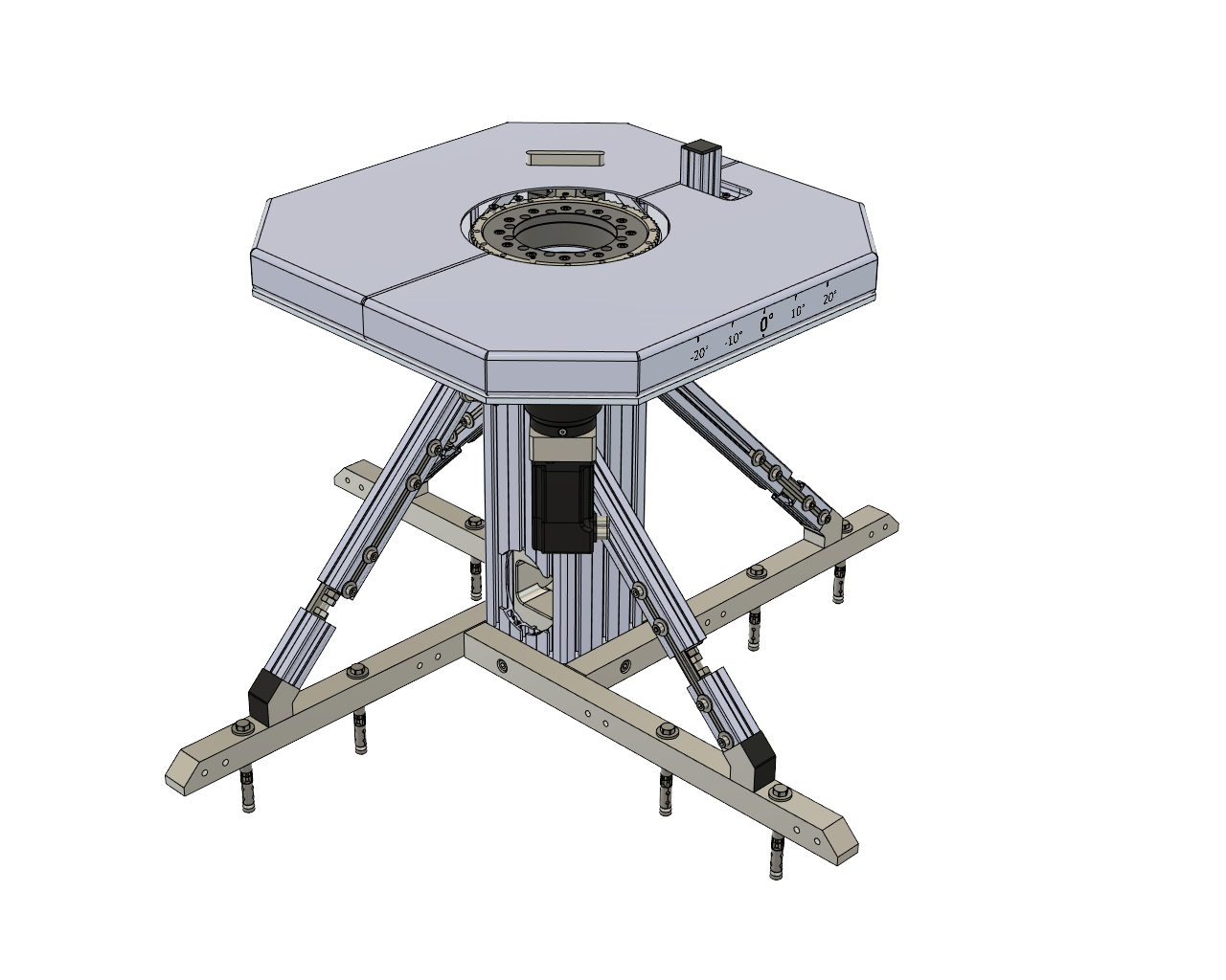
List of Parts#
Packet 1#
ID |
Pcs. |
Description |
|---|---|---|
A |
1 |
Table |
J |
1 |
Drill guide template, folded paper |
Packet 2#
ID |
Pcs. |
Description |
|---|---|---|
B |
4 |
Floor profile, 30x30x508 solid aluminum |
Bag 1#
ID |
Pcs. |
Description |
|---|---|---|
C |
4 |
Brace stump |
Bag 2#
ID |
Pcs. |
Description |
|---|---|---|
D |
4 |
Washer M8 |
Bag 3#
ID |
Pcs. |
Description |
|---|---|---|
E |
4 |
Swivel-in sliding block M8 |
F |
4 |
Half round screw M8x12 |
Bag 4#
ID |
Pcs. |
Description |
|---|---|---|
G |
1 |
Small Profile 30x30x80mm |
H |
1 |
Countersunk head screw M8x20 |
Bag 47#
ID |
Pcs. |
Description |
|---|---|---|
I |
8 |
Ground anchor |
Mounting instruction#
Step 1, 2: Brace Stump And Floor Profile#
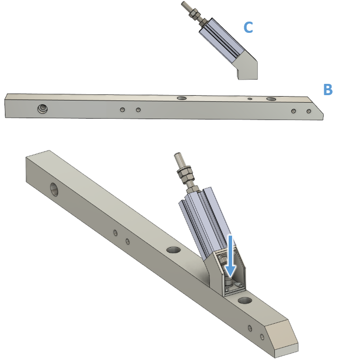
Mount a brace stump (C) with an M8x25 screw from the same bag without a washer to the floor profile (B).
The threaded rod of the brace stump has to face away from the chamfered edge of the floor profile as shown in the picture.
Place a M8 washer (D) from bag 2 on the threaded rod of the brace stump.
Repeat for all 4 floor profiles.
Step 3: Arrange Table#
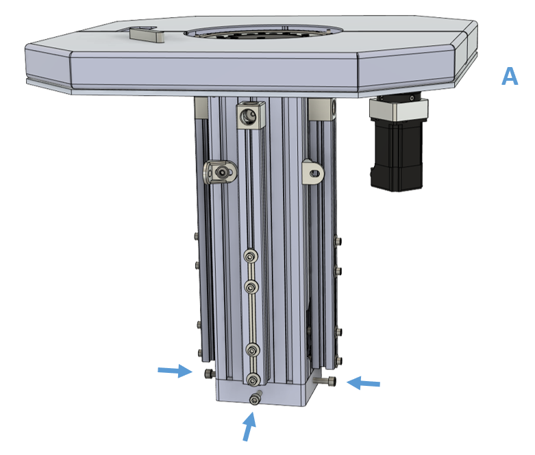
Arrange the table A upright, loosen and remove the four M8x40 screws at the bottom (one at each side) as shown in the picture.
Step 4, 5:#
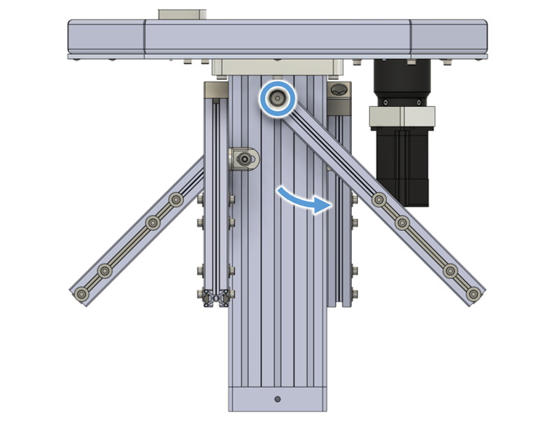
Loosen the screws (circle in picture) on every side of the table so you can rotate the cross braces outwards.
Mount the 4th cross brace which is packed individually in the same manner.
Step 6:#
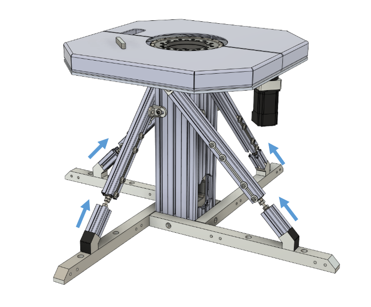
Plug the threaded rods of the brace stumps into the core drilling of the corresponding cross brace.
Step 7:#
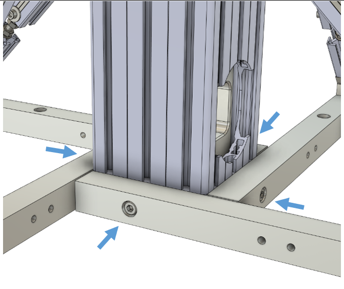
Attach the floor profile to the base of the table using the M8x40 screws from Step 3: Arrange Table.
Step 8, 9:#
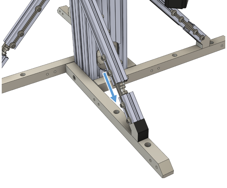
Loosen the screws on the left profile connector inside each cross brace and slide the connector down into to the brace stump as shown in the picture.
Attach the profile connector to the brace stump by tightening the lower two screws of the connector.
Note
Do not retighten the upper two screws of the connector at this point
Leave the right profile connector in the cross brace in its original position at this point.
Step 10:#
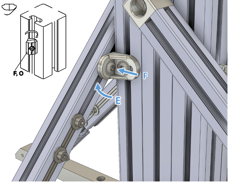
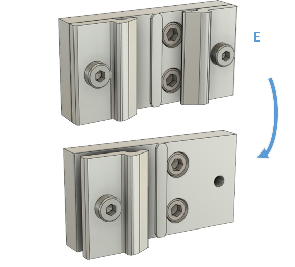
Insert swivel-in sliding blocks (E) into each of the 4 cross braces to mount the small brackets with M8x12 screws (F).
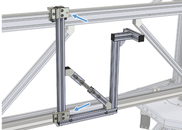
Step 11:#
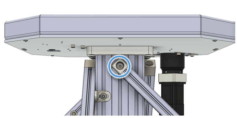
Fasten the upper mounting of the cross braces. Repeat this for all 4 brackets/profiles.
Step 12, 13:#
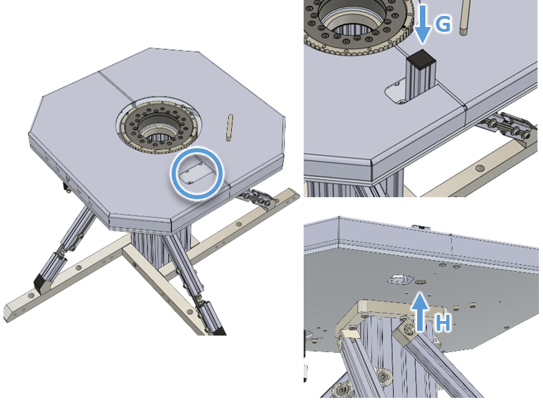
Remove premounted bolt (H) from the small profile (G).
Insert profile G into table at the indicated location and attach it with bolt (H) from the bottom side of the table.
Step 14 - 19:#
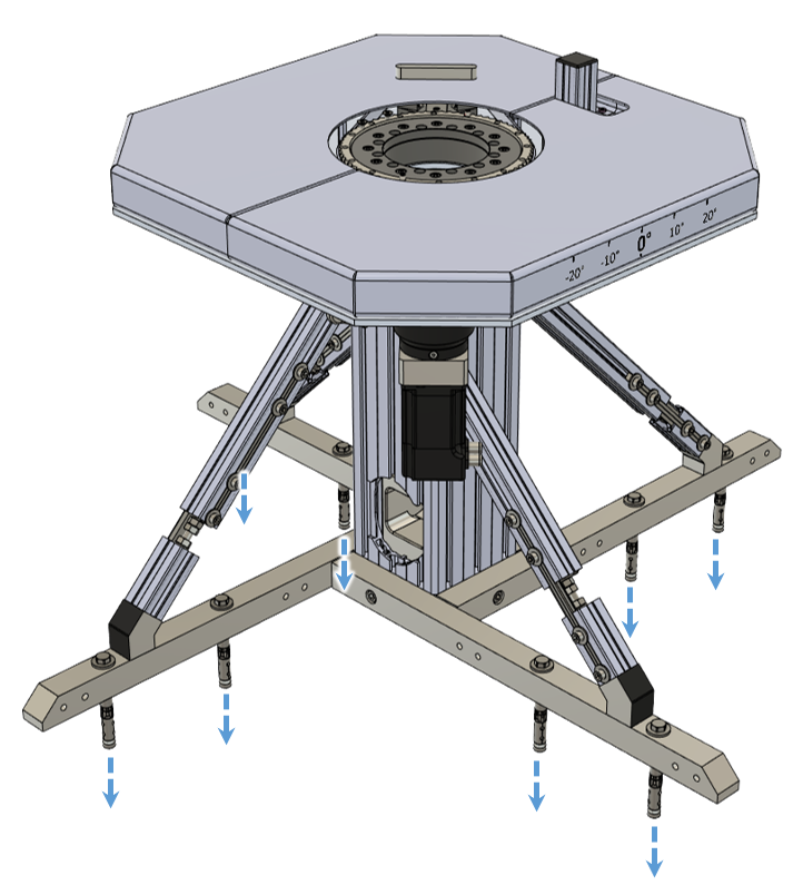
Unfold the drill guide and place it flat on the floor at the chosen NFS position.
Drill holes into the floor with a diameter of 12mm and a minimum depth of 80mm.
Clear the drilled holes of any debris with the blow-out pump.
Place the NFS table assembly on the drilled holes.
Insert all 8 ground anchors (I) through the holes of the floor profiles into the drilled holes with a hammer.
Tighten all 8 ground anchors (I) as tight as possible with the small 13mm wrench.
Stand assembly#
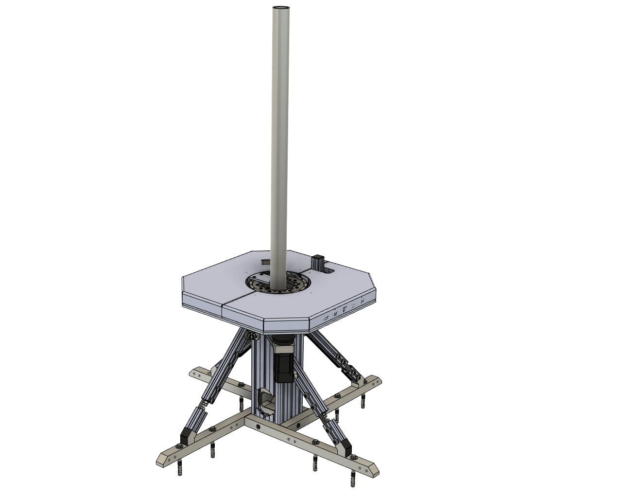
List of parts#
Bag 36#
ID |
Pcs. |
Description |
|---|---|---|
A |
1 |
Loudspeaker cable 4p (3m) |
B |
1 |
Loudspeaker extension cable 4p (10m) |
C |
1 |
Loudspeaker extension adapter |
Bag 9#
ID |
Pcs. |
Description |
|---|---|---|
D |
1 |
Rotary disk filler |
E |
2 |
M5x16 countersunk screw |
Packet 2#
ID |
Pcs. |
Description |
|---|---|---|
F |
1 |
Main Tube 50x1260 |
The heavy main tube (F) will be the stand of loudspeakers during measurements with the NFS. All loudspeaker cables need to pass through this tube. If you want to use some other kind of cable (like RCA or XLR for active speaker) it is convenient to also mount these cables at this step!
Mounting instructions#
Step 20:#
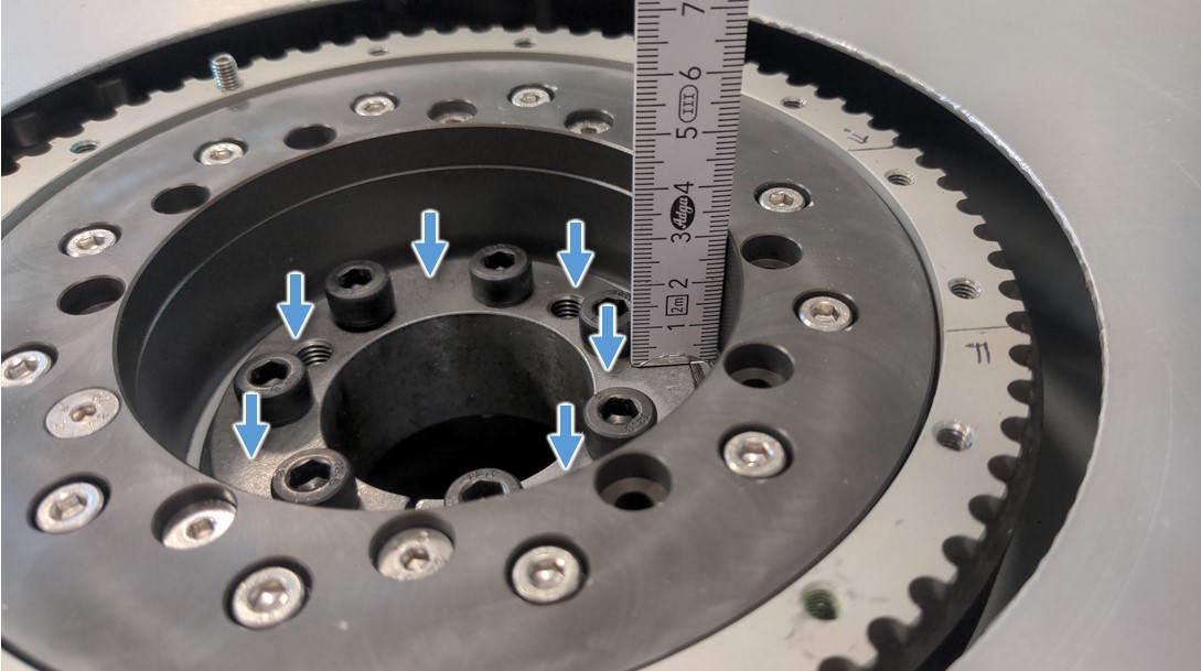
Measure the distance between the top of the locking assembly and the top of the pivot bearing as shown in the picture. Is this distance more than 28mm?
Step 21:#
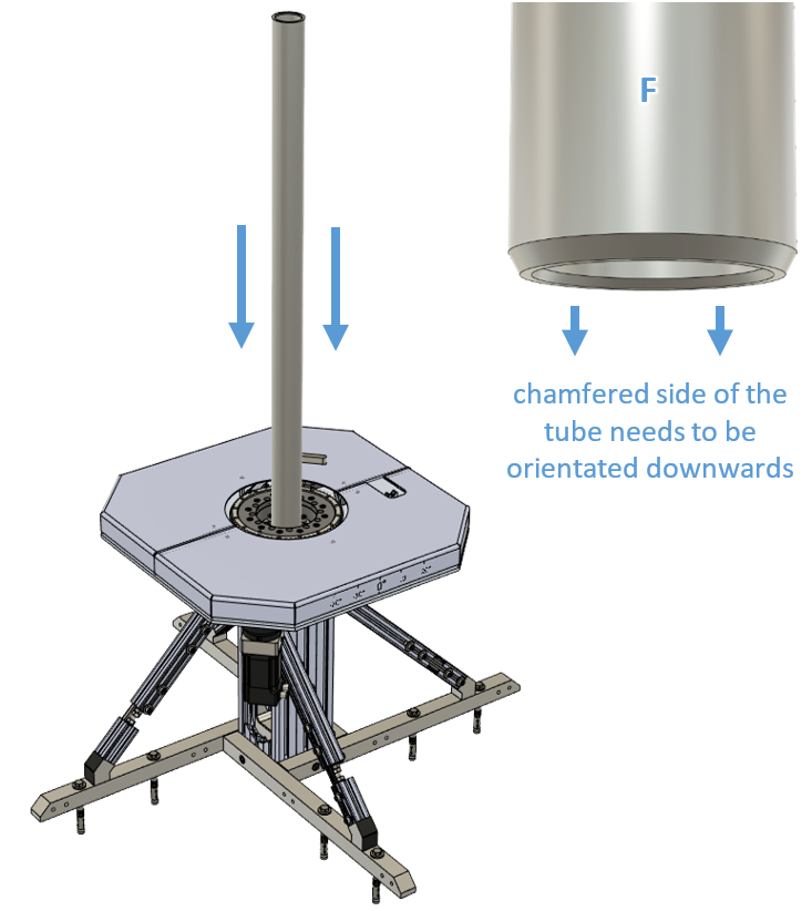
Insert the main tube (F) through the center hole of the locking assembly in the table, with the chamfered edge of the main tub facing downwards.
Step 22:#
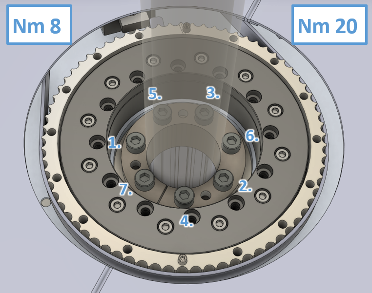
Gradually tighten the screws of the locking assembly in a cross-pattern order as indicated in the picture.
First: tighten all screws hand tight with the screwdriver handle.
Second: tighten all screws to 8 Nm with the torque wrench.
Third: tighten all screws to the final installation torque of 20 Nm with the torque wrench.
Step 23:#
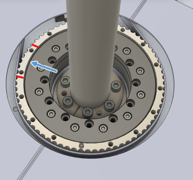
Locate the marked position on the gear in the table assembly. (Red permanent marker)
Step 24:#
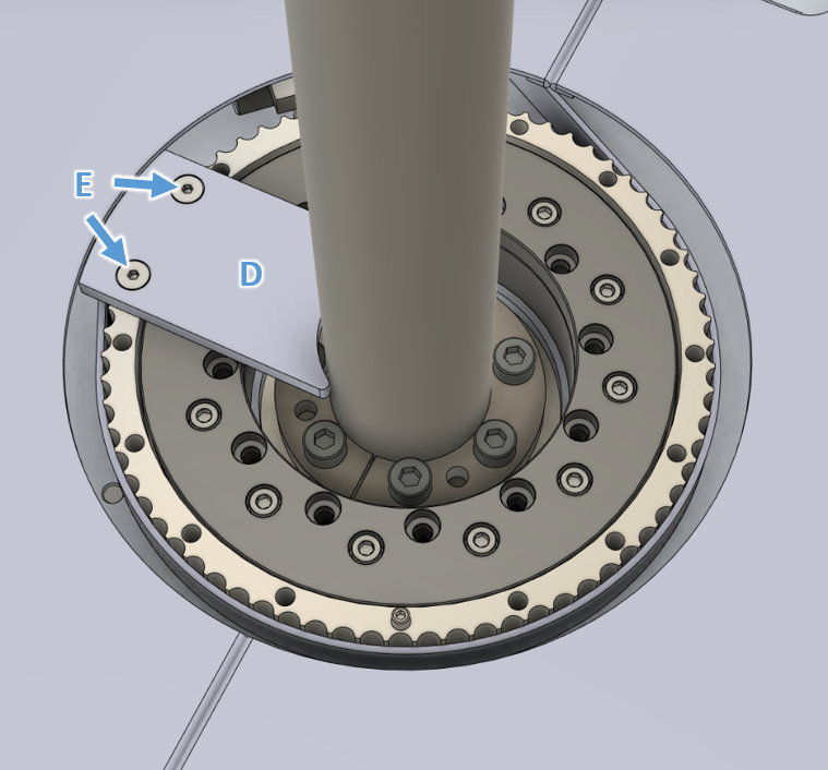
Install the rotary disk filler (D) with the M5 countersunk screws (E) at the indicated location of the gear in the table assembly.
Step 25-27#
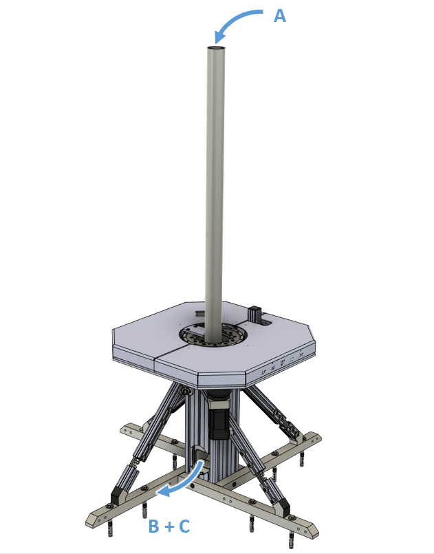
Run the loudspeaker cable (A) through the main tube with the speak-on plug facing downwards and the banana plugs facing upwards.
Attach the extension adapter (C) and the loudspeaker extension cable (B).
Run additional cables in the same manner if needed. (for example XLR, RCA or power for active speakers)
Step 28#
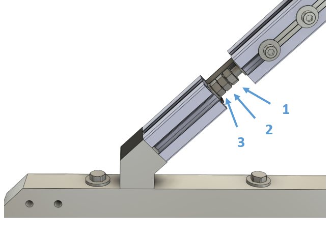
The stand must now be adjusted to so that the main tube is in a vertical level. For this purpose, the nuts on the brace stumps are used.
Nut 1: Used for level adjustment.
Nut 2: Counter-nut used to fix nut 1 after adjustment.
Nut 3: Fixes thread in the brace stump. No further tightening needed.
Step 29#
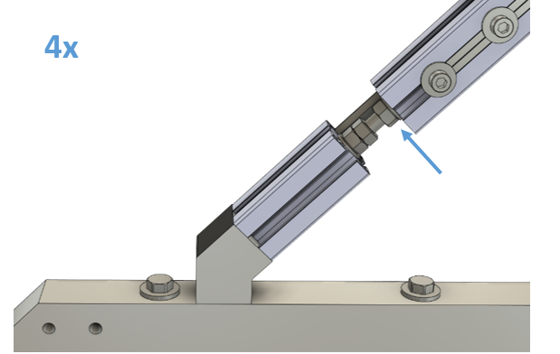
Gradually tighten the upper nuts (nut 1) of the cross braces on all 4 sides, so that tilting of the table is no longer possible.
Step 30#
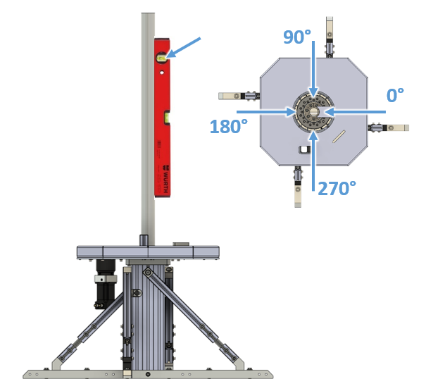
Check the incline of the main tube using the spirit level. Measure on all 4 locations (0°, 90°, 180° and 270°)
Step 31-32#
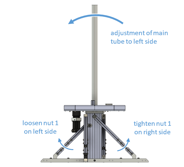
Adjust the main tube incline to the horizontal level if needed with the nuts of the cross braces.
Adjust the tension of the upper nut 1 on two opposing cross brace to adjust the incline as shown in the example picture.
Attention: Always decrease the tension of the nut on one brace before increasing the tension of the opposite brace.
Step 33-34#
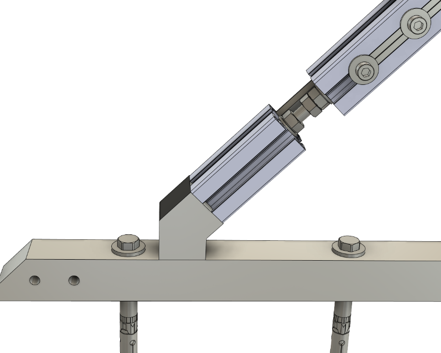
After adjusting the incline of the main tube, counter the upper nut 1 of each cross brace with the second nut 2.
Use a second 13 mm combination wrench to tighten nut 2 while holding nut 1 with the first wrench.
Step 35-36#
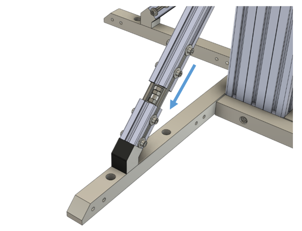
Loosen the screws on the second profile connector inside each cross brace and slide them also down into the brace stumps.
Tighten all screws in all of the 8 profile connectors.
Side arm assembly#
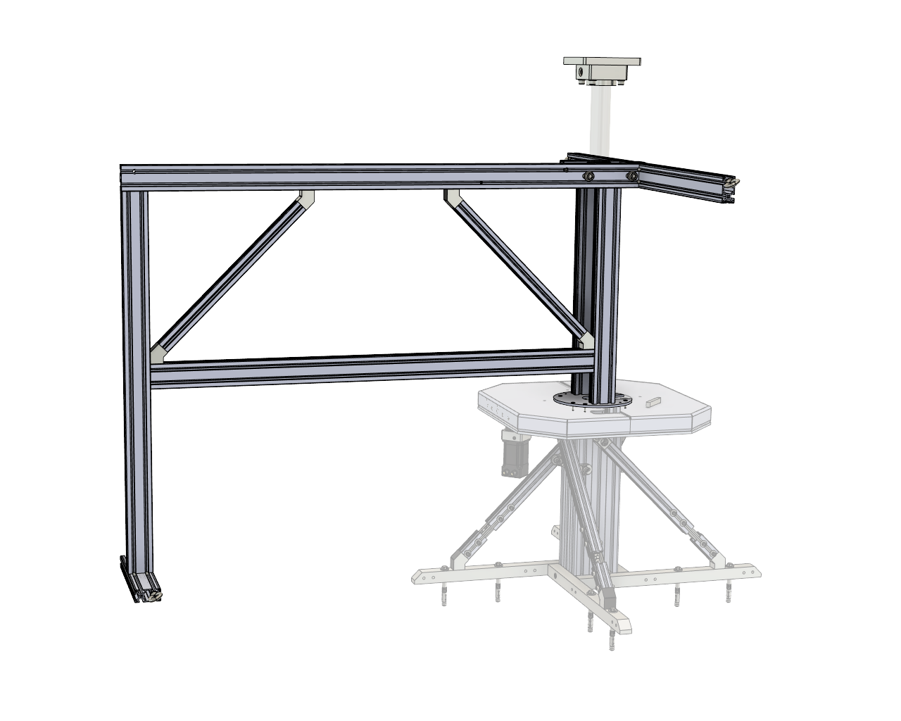
List of parts#
Packet 1#
ID |
Pcs. |
Description |
|---|---|---|
A |
1 |
Loudspeaker carrier |
Packet 2#
ID |
Pcs. |
Description |
|---|---|---|
B |
1 |
Inner vertical profile A 30x60x540 (! 2 holes !) |
C |
1 |
Inner vertical profile B 30x60x540 (! 1 hole !) |
D |
1 |
Gable profile 30x60x1000 with thread-block |
E |
1 |
Lower gable profile 30x60x300 |
F |
1 |
Lower horizontal profile 30x60x1100 |
G |
1 |
Upper horizontal profile 30x60x1265 |
H |
1 |
Outer vertical profile 30x60x900 |
I |
2 |
Cross brace profile 30x30x463 with 2x45° angles |
J |
1 |
Cross brace profile 30x30x500 with 2x45° angles |
K |
1 |
Cross brace profile 30x30x450 with 2x hinges |
Bag 5#
ID |
Pcs. |
Description |
|---|---|---|
L |
6 |
Screw M8x40 |
Bag 6#
ID |
Pcs. |
Description |
|---|---|---|
M |
10 |
Screw M8x70 |
Bag 7#
ID |
Pcs. |
Description |
|---|---|---|
N |
2 |
T-nut M6 |
O |
1 |
Low profile screw M6x12 |
P |
1 |
Low profile screw M6x20 |
Bag 8#
ID |
Pcs. |
Description |
|---|---|---|
Q |
6 |
Washer M6 |
R |
6 |
T-nut M6 |
S |
2 |
Screw M6x12 |
T |
4 |
Screw M6x25 |
Bag 11#
ID |
Pcs. |
Description |
|---|---|---|
U |
1 |
Pillow block bearing |
Bag 9#
ID |
Pcs. |
Description |
|---|---|---|
V |
1 |
Rotary disk |
W |
6 |
Countersunk screw M5x16 |
X |
4 |
Countersunk screw M8x20 |
Bag 10#
ID |
Pcs. |
Description |
|---|---|---|
Y |
1 |
Profile 30x60x150 |
Bag 12#
ID |
Pcs. |
Description |
|---|---|---|
Z |
4 |
Washer M12 |
AA |
2 |
Nut M12 |
BB |
1 |
Screw M10x70 |
CC |
2 |
Screw M12x180 |
Bag 13#
ID |
Pcs. |
Description |
|---|---|---|
DD |
4 |
Eye bolt M8 |
EE |
4 |
Endcap for strut profiles (with hole) |
Bag 31#
ID |
Pcs. |
Description |
|---|---|---|
FF |
4 |
Cap for 45° connector |
Packet 2#
ID |
Pcs. |
Description |
|---|---|---|
GG |
1 |
Profile 30x60x500 |
Bag 37#
ID |
Pcs. |
Description |
|---|---|---|
HH |
4 |
Profile connectors |
Mounting instructions#
Step 37#
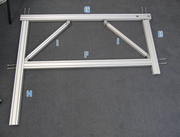
Identify and arrange the profiles (B), (F), (G), (H) and (I) as shown in the picture.
Step 38-40#
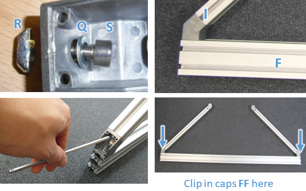
Install 2x cross braces (I) on the lower horizontal profile (F)using M6x12 screws (S), M6 washers (Q) and T-nuts (R) as shown in the picture.
The 45° angle connectors must be located at the end of the horizontal profile (F) and the cross braces (I) must face inwards.
Clip caps (FF) into the 45° angles.
Step 41-42#
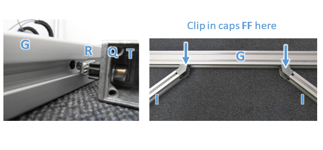
Loosely fix T-nut (R) onto M6x25 screw (T) with M6 washer (Q) on the other side of each cross brace (I) and mount them to the upper horizontal profile (G) using the holes in the middle of the profile (G).
Clip caps (FF) into the 45° angles.
Step 43#
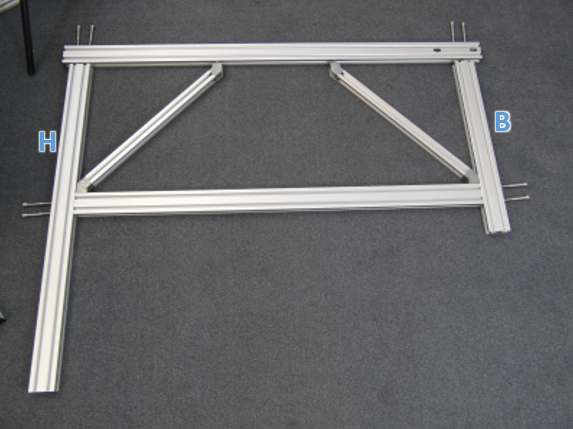
Mount the vertical profiles (B) and (H) wit M8x70 screws (M) to the structure. Make sure, the counterbore in the profiles are facing outwards so that the screw heads are flush wit the profiles when mounted.
Step 44#
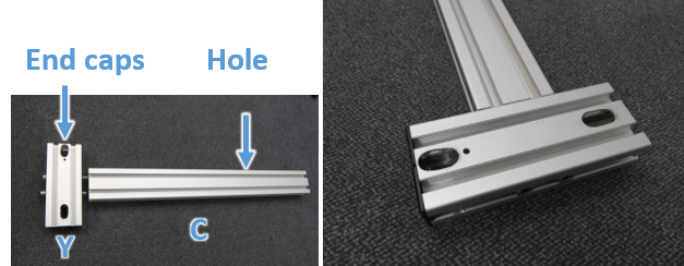
Mount the second inner vertical profile (C) to the small horizontal profile (Y) using M8x70 screws (M). Make sure, the end caps in the profile (Y) are facing in the same direction as the hole in profile (C).
Step 45-46#
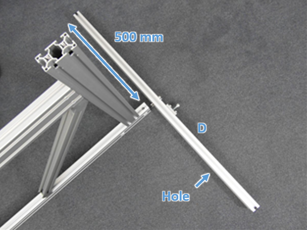
Place the previously mounted arm structure in an upright position, with the upper horizontal profile (G) located on the bottom towards the floor.
Mount the gable profile (D) to the structure using M8x40 screws (L). Make sure the hole in the gable profile is located on the longer leg of the profile.
Step 47-48#
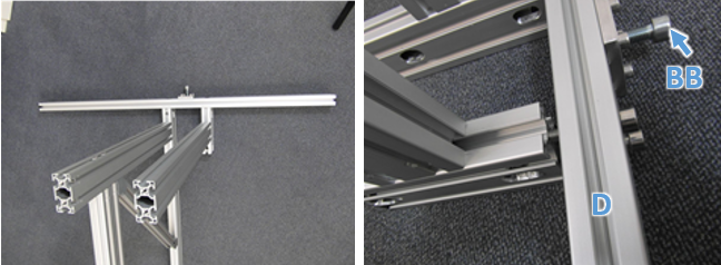
Mount the sub assembly from step (43) to the gable profile (D) using M8x40 screws (L).
Screw a M10x70 screw (BB) into the small plate at gable profile (D) until it is coming out across.
Step 49#

- Mount the lower gable profile (E) to the structure usin M8x40 screws (L).(The threads at the open face ends should point inwards as marked in the picture.)
Step 50#
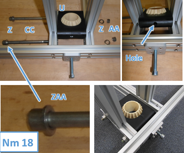
Place the pillow block bearing (U) between the profiles and insert the M12 screws (CC) with washers (Z). Make sure the Hole in the pillow block faces towards the gable profile (D). Fix the M12 screws with nuts (AA) and washers (Z). Thighten the M12 screws with the torque wrench to 18 Nm. (Counter the nuts with the 19mm wrench)
Step 51#
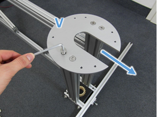
Mount rotary disk (V) to the structure with four screws (X). The opening must face away from the arm structure as seen in the picture.
Note
Make sure the opening faces away from the arm structure.
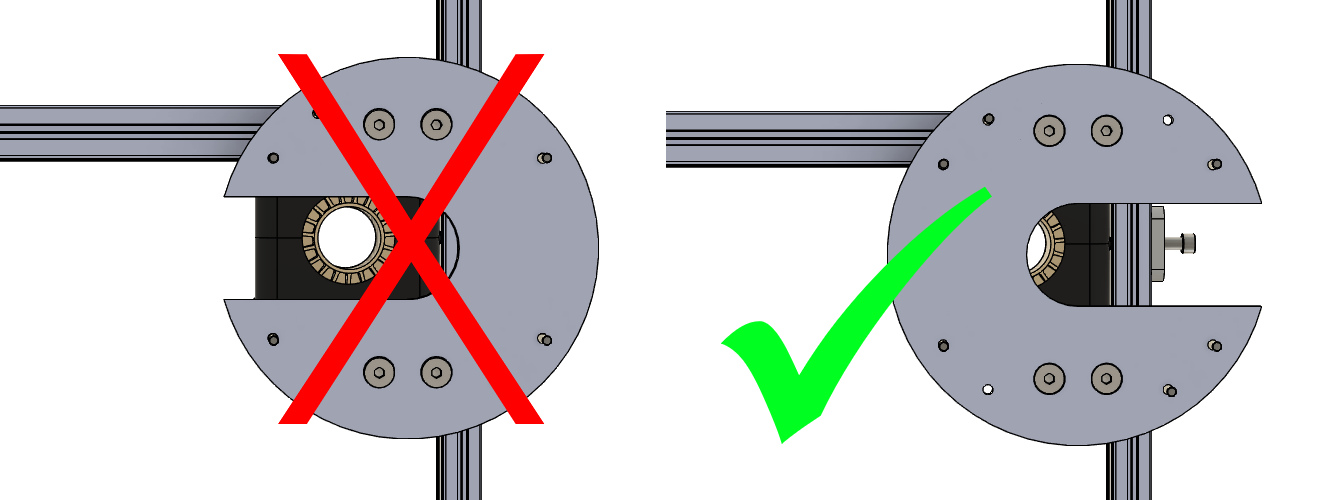
Step 52#
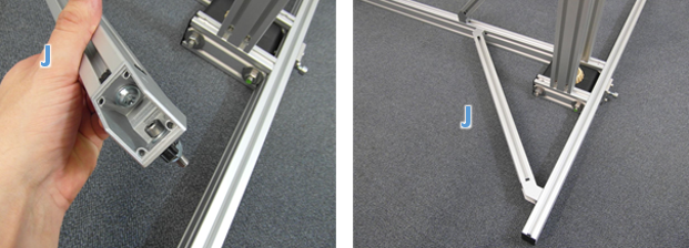
Mount cross brace (J) to the structure using M6x25 screws (T) with washers (Q) and T-Nut (R) by using the designated holes.
Step 53-54#
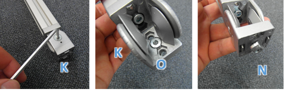
Loosen the two screws on each hinge of brace (K) a bit so tha the hinges can be rotated.
Insert M6x12 screw (O) into the middle hole of a hinge on one side of the brace (K) and loosely fix it with a T-Nut. (N)
Step 55-56#
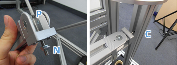
Insert M6x12 screw (P) with T-Nut (N) into the hinge on the other side.
Plug the hinge with the long screw (P) into the hole of the profile (C).
Step 57-58#
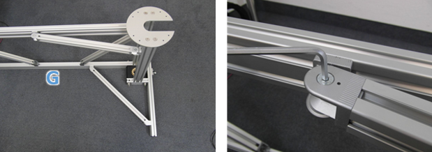
Plug the second end of the brace to profile (G) and tighten the screws on both ends.
Tighten the four lateral screws of the hinges to fix them against rotation.
Step 59#
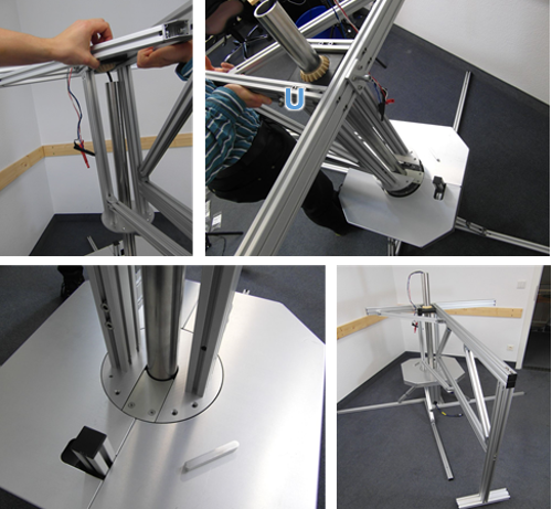
Mount the side arm on the table by sliding the pillow block bearing (U) over the steel tube.
Take care of the loudspeaker cable which has to run through the pillo block bearing (U).
Step 60#
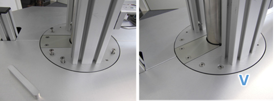
Secure the sidearm by fixing the rotary disk (V) with six screws (W).
Step 61#
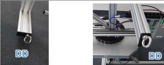
Install the 4 Eyebolts (DD) into the ends of the lower gable (E) and upper gable profile (D).
Step 62-63#
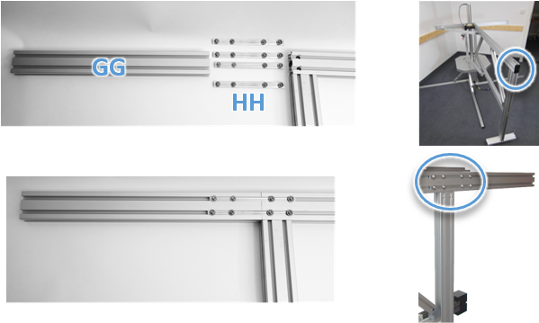
- R-Axis Extension:(optional)The movement range of the R-Axis can be extended with an extra 30x60x500m profile (GG).
Use 4 profile connectors (HH) to mount the profile (GG) on th side arm.
Step 64-67#
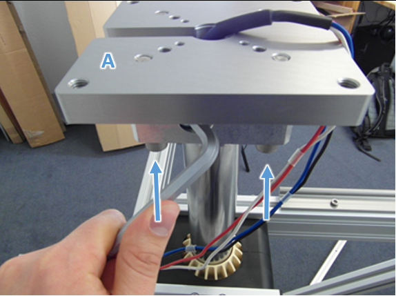
Place the loudspeakercarrier (A) on the main tube of the stand.
Loosen the screws on the bottom of the loudspeaker-carrier just a bit.
Settle the loudspeaker-carrier fitting to the top of the tube.
Tighten the flange bolt first before retightening the screws on the bottom.
R linear axis assembly#
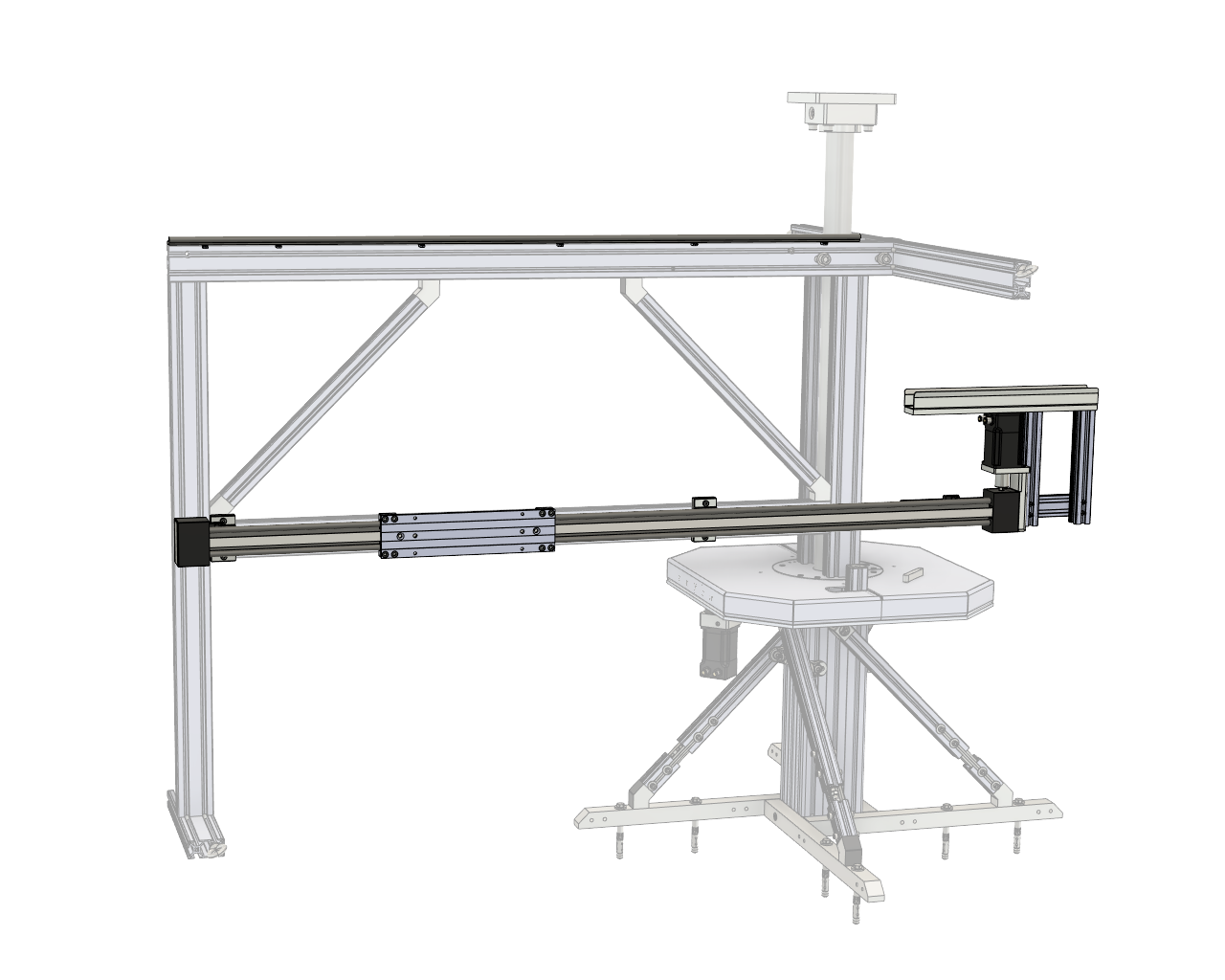
List of parts#
Packet 1#
ID |
Pcs. |
Description |
|---|---|---|
A |
1 |
R-Axis cable fixture |
Packet 2#
ID |
Pcs. |
Description |
|---|---|---|
B |
1 |
Support rail |
Packet 3#
ID |
Pcs. |
Description |
|---|---|---|
C |
1 |
R linear axis with motor |
Bag 14#
ID |
Pcs. |
Description |
|---|---|---|
D |
2 |
R-Axis clamping block |
Bag 15#
ID |
Pcs. |
Description |
|---|---|---|
E |
6 |
T-nut M6 |
F |
6 |
Low profile screw M6x10 |
Bag 16#
ID |
Pcs. |
Description |
|---|---|---|
G |
2 |
Slot nut M5 |
H |
2 |
Screw M5x8 |
Additional Information#
The R-Axis is shipped in a configuration with only two bearing blocks mounted on the upper rail and two bearing blocks in a parking position near the motor on the lower rail. This is intended and reduces friction during movement. Do not remount the lower bearing blocks!
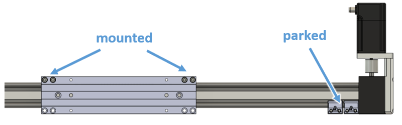
Mounting instructions#
Step 68-70#
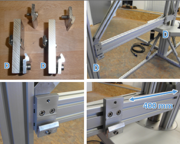
Prepare the two r-axis-clamping blocks (D), by removing the upper clamp as seen in the picture
Mount the two r-axis- clamping blocks (D) to the lower horizontal profile of the sidearm.
Mount the inner r-axis- clamping blocks (D) 400 mm away from the end of the profile
Step 71-73#
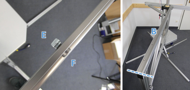
Use Screw (F) with T-nut (E) to mount the support rail (B) on the top side of the upper horizontal profil of the side arm.
Repeat this for all 6 screws at every second hole.
Place the end of the support rail flush with the end of the upper horizontal side arm profile.
Step 74-75#
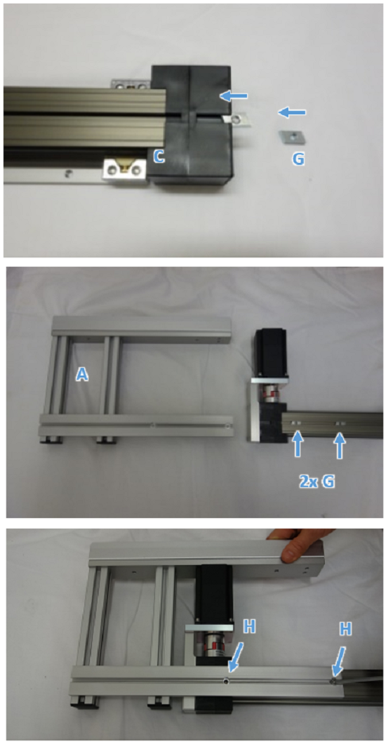
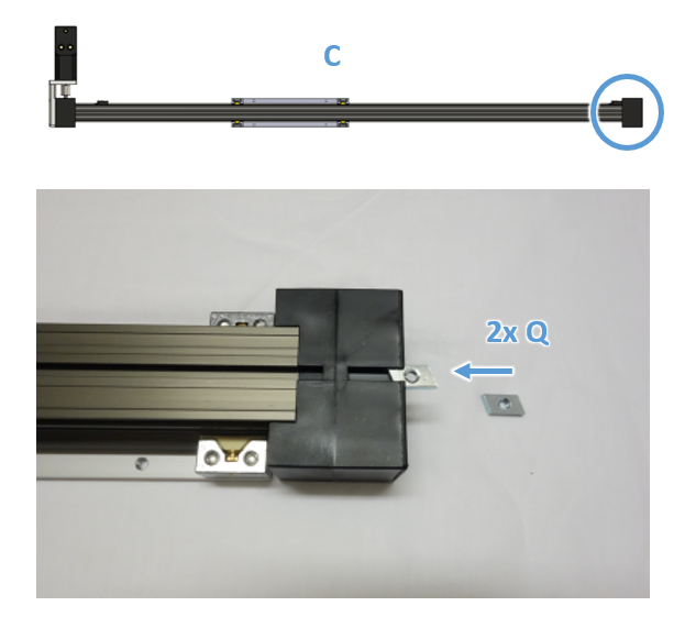
74. Insert 2 slot nuts (G) on the back side of the r-linear axis (C).
75. Mount the cable fixture (A) with the M5 screws (H) to the linear axis using the 2 M5 slot nuts (G).
Step 76#
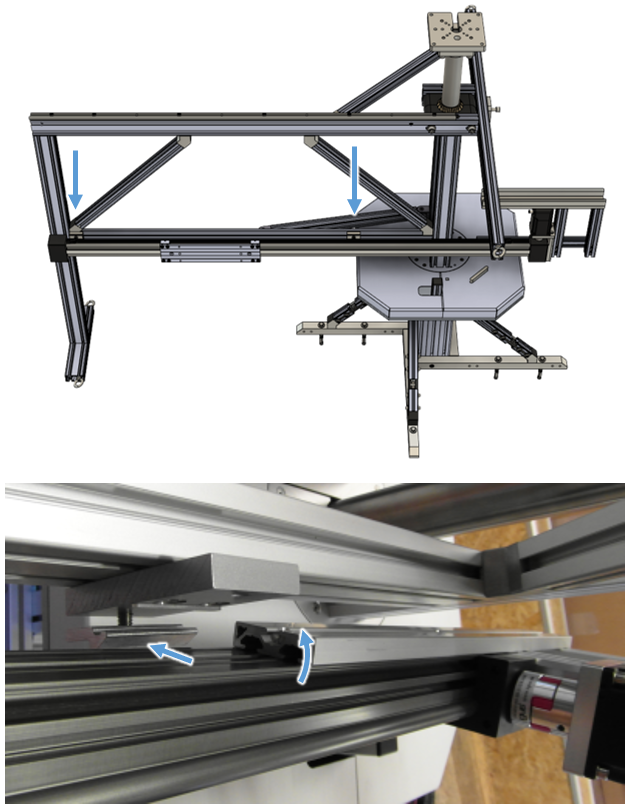
Mount the r-linear axis (C) to the side arm.
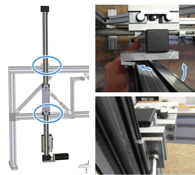
First fit the axis to the lower claws of the clamping blocks.
Then tilt the axis up to snap the tongue of the clamping block into the groove on the back of the axis and secure the axis by remounting the upper claws of clamping blocks.
Step 77#
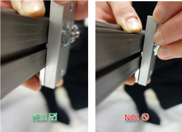
Make sure the tongues of the clamping blocks (D) are correctly fitted to the groove of the axis! (see pictures for reference to correct and incorrect fit of the tongue).
Step X#
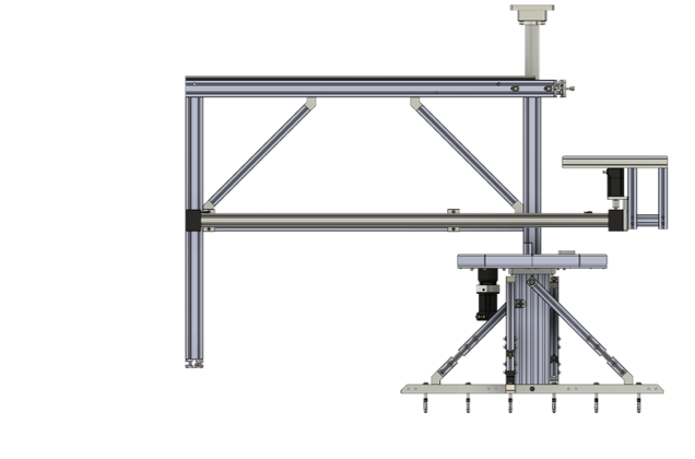
Smallest Configuration:
Position the R-Axis so that the black end cap does not exceed the length of the side arm as seen in the picture.
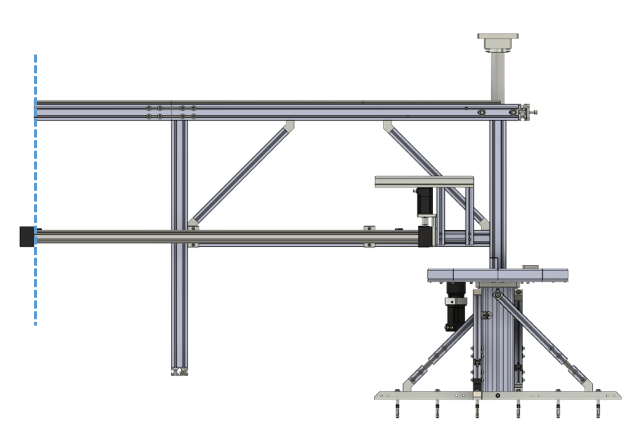
Largest Configuration:
Shift the R-Axis out until the black end cap of the axis just exceeds the R-Axis Extension as seen in the picture. (R-Axis extension from step step 61 must be mounted.)
R/Z connector assembly#
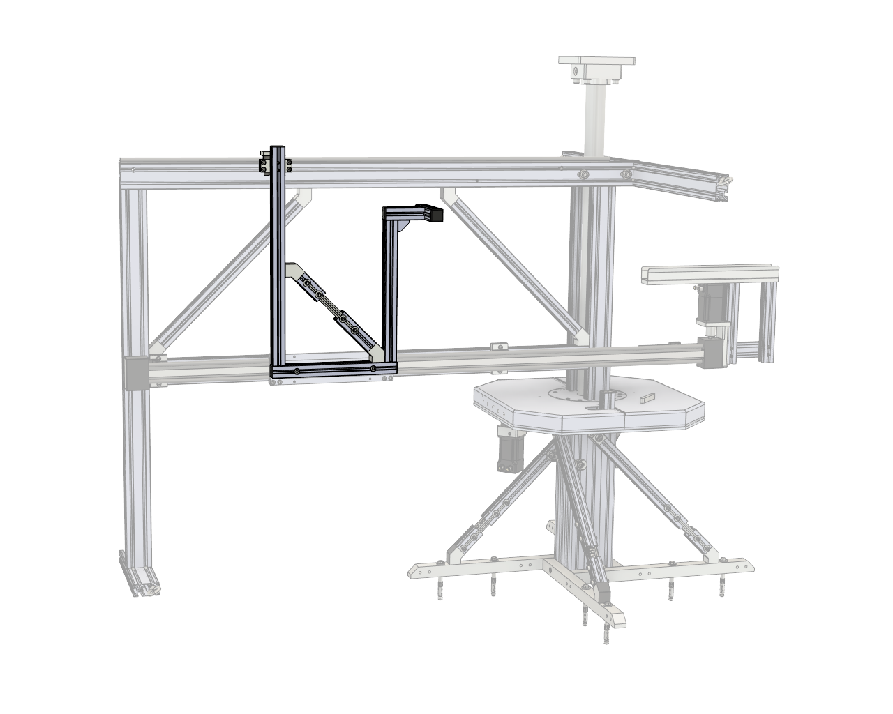
List of parts#
Packet 2#
ID |
Pcs. |
Description |
|---|---|---|
A |
1 |
Profile 30x30x510 |
B |
1 |
Profile 30x30x300 |
C |
1 |
Profile 30x30x340 |
D |
1 |
Adjustable cross brace |
Bag 17#
ID |
Pcs. |
Description |
|---|---|---|
E |
2 |
Washer M6 |
F |
2 |
T-nut M6 |
G |
2 |
Screw M6x12 |
H |
2 |
Screw M8x30 |
I |
2 |
Washer M8 |
J |
2 |
Screw M8x40 |
K |
3 |
Endcap for strut profiles |
Bag 18#
ID |
Pcs. |
Description |
|---|---|---|
L |
1 |
Drift compensator |
Bag 19#
ID |
Pcs. |
Description |
|---|---|---|
M |
1 |
T-piece |
Bag 31#
ID |
Pcs. |
Description |
|---|---|---|
N |
2 |
Cap for 45° connector |
Mounting instructions#
Step 78#
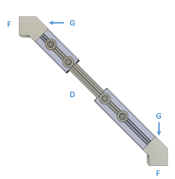
Install M6 screws (G) on both 45° brackets of the adjustabl cross brace (D) with T-nuts (F).
Step 79#
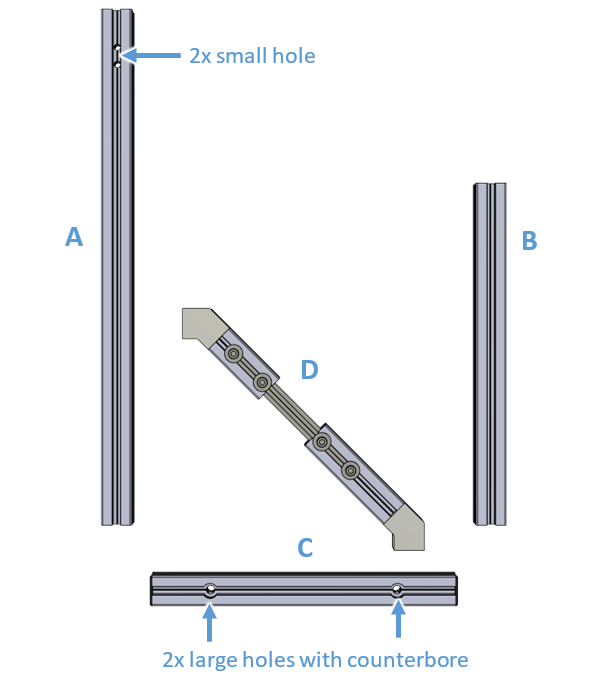
Arrange the cross brace (D) together with the profiles (A, B, C) as seen in the picture.
Step 80-81#
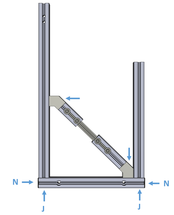
Mount all profiles together with M8x40 screws (J) and the M screws + T-nuts in the cross brace.
Mount the structure lying on a flat surface (for example table). It is important that the structure forms a flat plane and is not warped!
Mount endcaps (N) on the open face ends of profile (C).
Step 82#
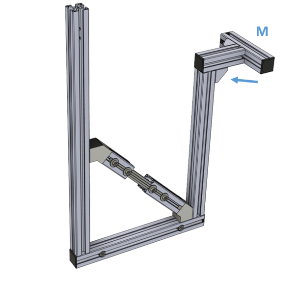
Mount the T-Piece (M) to the structure as seen in the picture (Use the premounted screw and T-nut in the T-piece.)
Step 83#
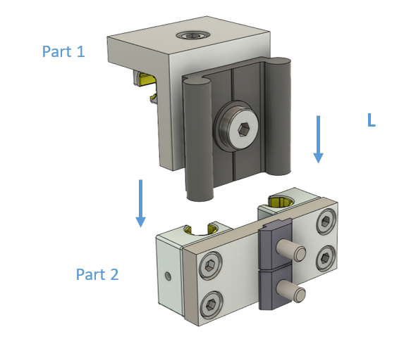
Separate the two parts of the drift compensator (L).
Step 84#
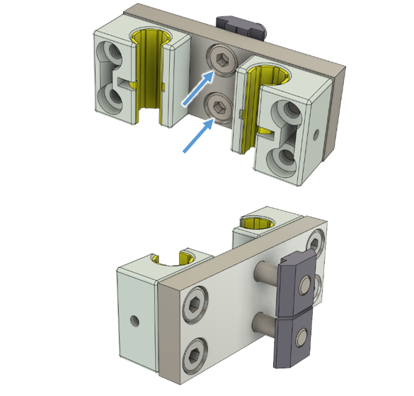
Loosen the two screws of part 2 of the drift compensator until the T-nuts barely stay on the screw as shown in the picture.
Step 85#
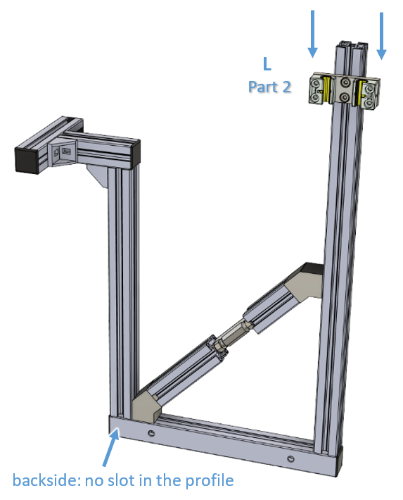
Slide part 2 of the drift compensator into the backside of profil (A) of the structure and mount it at the position indicated by th two small holes.
Step 86#
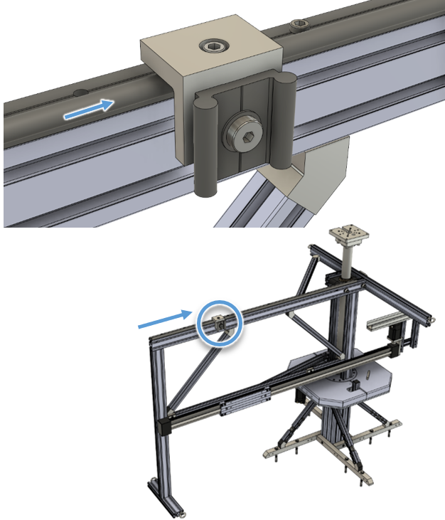
Slide part 1 of the drift compensator onto the upper support rail of the main NFS structure as shown in the picture.
Step 87#
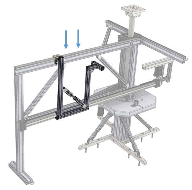
Reconnect both parts of the drift compensator by sliding in the R/Z connector from the top.
Step 88#
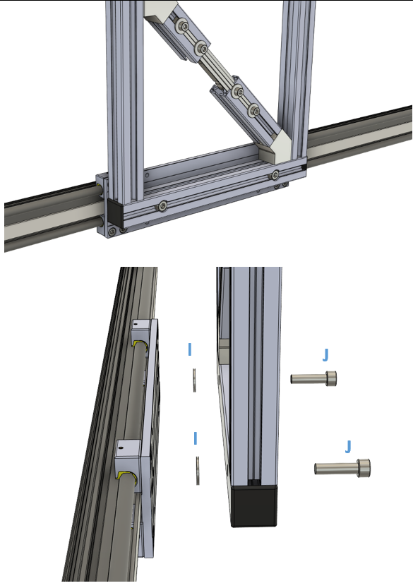
Mount the R/Z-connector to the carriage of the R-axis using M8x40 screws (J) and install washers (I) between both parts.
Step 89#
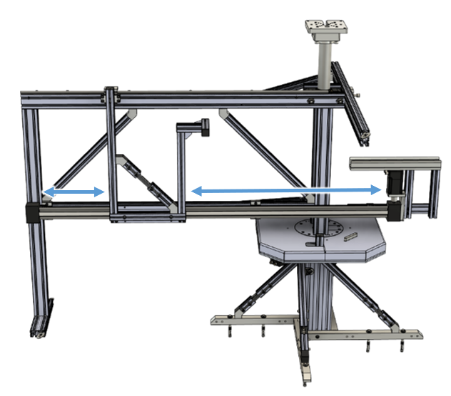
Check that the R-axis moves without excessive friction. Move the R/Z connector by hand over the entire travel range of the R-axis.
If moving the R-Axis this way requires much force (> 100N, equal weight of 10 kg) check the correct seat of the R-axis (step 75/76).
If moving the R-Axis is still difficult, loosen the screws on the upper support rail, move the R-Axis by hand and retighten the upper screws.
Z linear axis assembly#
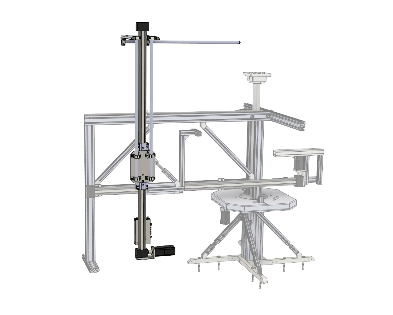
List of parts#
Packet 2#
ID |
Pcs. |
Description |
|---|---|---|
A |
2 |
Aluminum tube 20x900 |
B |
1 |
Microphone boom 20x800 with adapter screw |
Packet 3#
ID |
Pcs. |
Description |
|---|---|---|
C |
1 |
Z linear axis with motor |
Box 2#
ID |
Pcs. |
Description |
|---|---|---|
D |
1 |
Z-Axis Control |
Bag 20#
ID |
Pcs. |
Description |
|---|---|---|
E |
2 |
Z-axis clamping blocks (2 T-Nuts) |
Bag 21#
ID |
Pcs. |
Description |
|---|---|---|
F |
8 |
Low profile screw M6x12 |
G |
2 |
Screw M6x12 |
H |
10 |
Lock washer M6 |
I |
1 |
Screw M8x12 |
J |
1 |
Lock washer M8 |
K |
1 |
Z-Axis clamping plate |
Bag 22#
ID |
Pcs. |
Description |
|---|---|---|
L |
4 |
Horizontal clamp |
M |
1 |
Microphone ball head |
N |
1 |
Microphone thread adapter (Spare Part for Special Use) |
Bag 46#
ID |
Pcs. |
Description |
|---|---|---|
O |
1 |
Microphone holder set |
Bag 25#
ID |
Pcs. |
Description |
|---|---|---|
P |
2 |
Screw M5x6 |
Q |
2 |
Slot nut M5 |
Mounting instructions#
Step 90#
Prepare both z-axis clamping blocks (E) by removing the right clamp and loosening the left one.
Step 91#
Mount the two z-axis clamping blocks with M6 screws and t-nuts (premounted in clamping block) at the top and bottom of the left vertical profile R/Z connector.
Step 92#
Insert 2 slot nuts (Q) on the back side of the linear axis (C).
Step 93#
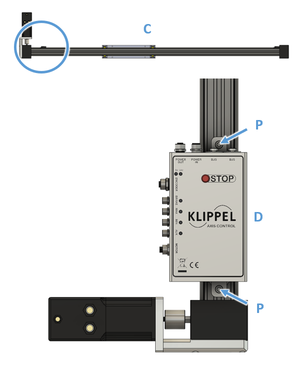
Mount the Z-Axis Control (D) to the z linear axis with M5 screws (P) two slot nuts inserted in step 91.
Important:
Motor/Encoder Connectors of the Axis Control must face towards motor
Step 94-97#
Mount the z linear axis to the clamping blocks on the R/Z conenctor.
First snap the axis into the left clamp.
Then seat the tongue of the clamping block into the back groove of the z axis.
Then remount the right clamps from step 89.
Step 98#
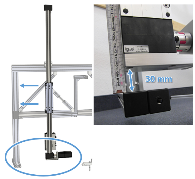
Adjust the z axis mounting height to a clearance of 30 mm between its lower end and the lowest horizontal profile of the side arm. Loosen all clamps slightly to shift the z-axis. Tighten all clamps when the axis is in position.
Carefully pull the z-axis into position by moving the r-axis manually.
Step 99-101#
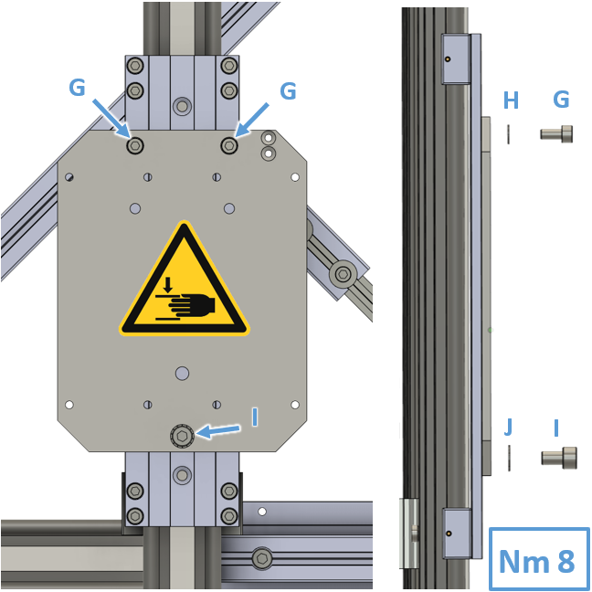
Mount the Z-Axis clamping plate (K) to the carriage on the Z-linear axis.
Use M6 screws (G) with lock washers (H) for the two upper mountings.
Use M8 screw (I) and lock washer (J) for th mounting on the lower carriage. Only tighten the M8 screw (I) to 8 Nm!
Note
The position of the carriage and the Z- Axis Control can be changed. To do this, the brake should be released by connecting the brake cable to the AUX input of the Z- Axis Control (See step 154- 158).
Step 102#
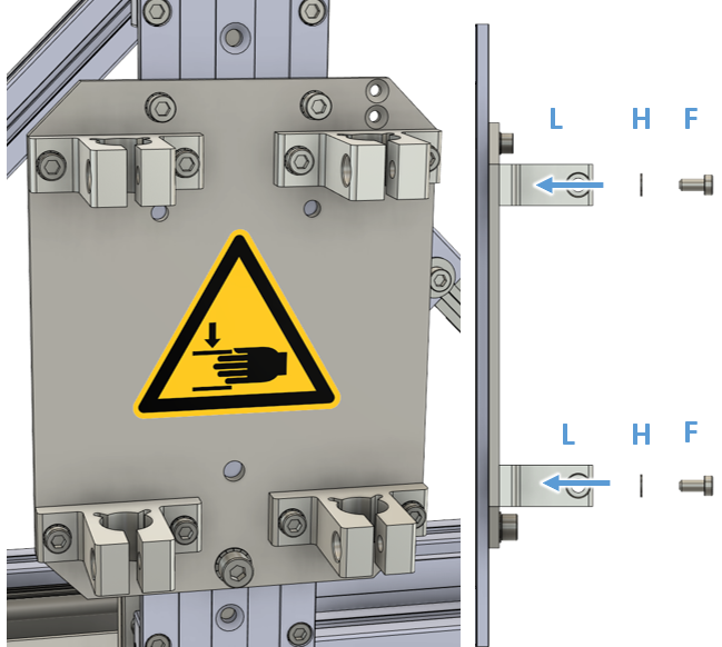
Mount the 4x horizontal clamps (L) on the Z-Axis clamping plate using low profile M6 screws (F) and lock washer (H)
Step 103-104#
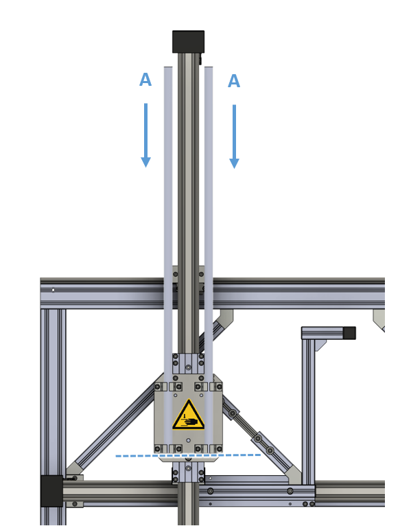
Slide the 900 mm aluminum tubes (A) into the horizontal clamps until the tubes line up with the bottom horizontal clamps.
Thighten the screws of the horizontal clamps to fix the aluminum tubes.
Step 105#
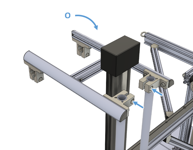
Slide the microphone holder set (O) on top of the two aluminum tubes as indicated in the picture and tighten the two indicated clamps.
Step 106#
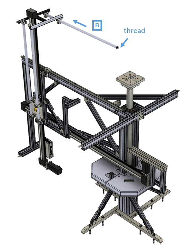
Slide the microphone boom (B) into the microphone holder set with the threaded end facing towards the center of the NFS and tighten the two remaining clamps of the holder.
Step 107#
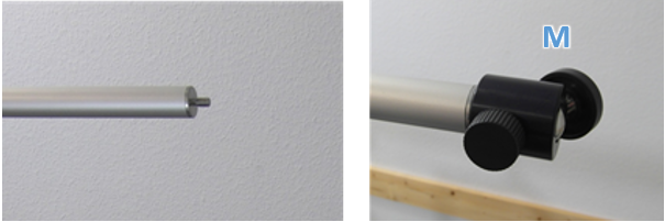
step107. Screw the ball head (M) on to the threaded end of the tube.
Axis Control and limit switches -assembly and wiring#
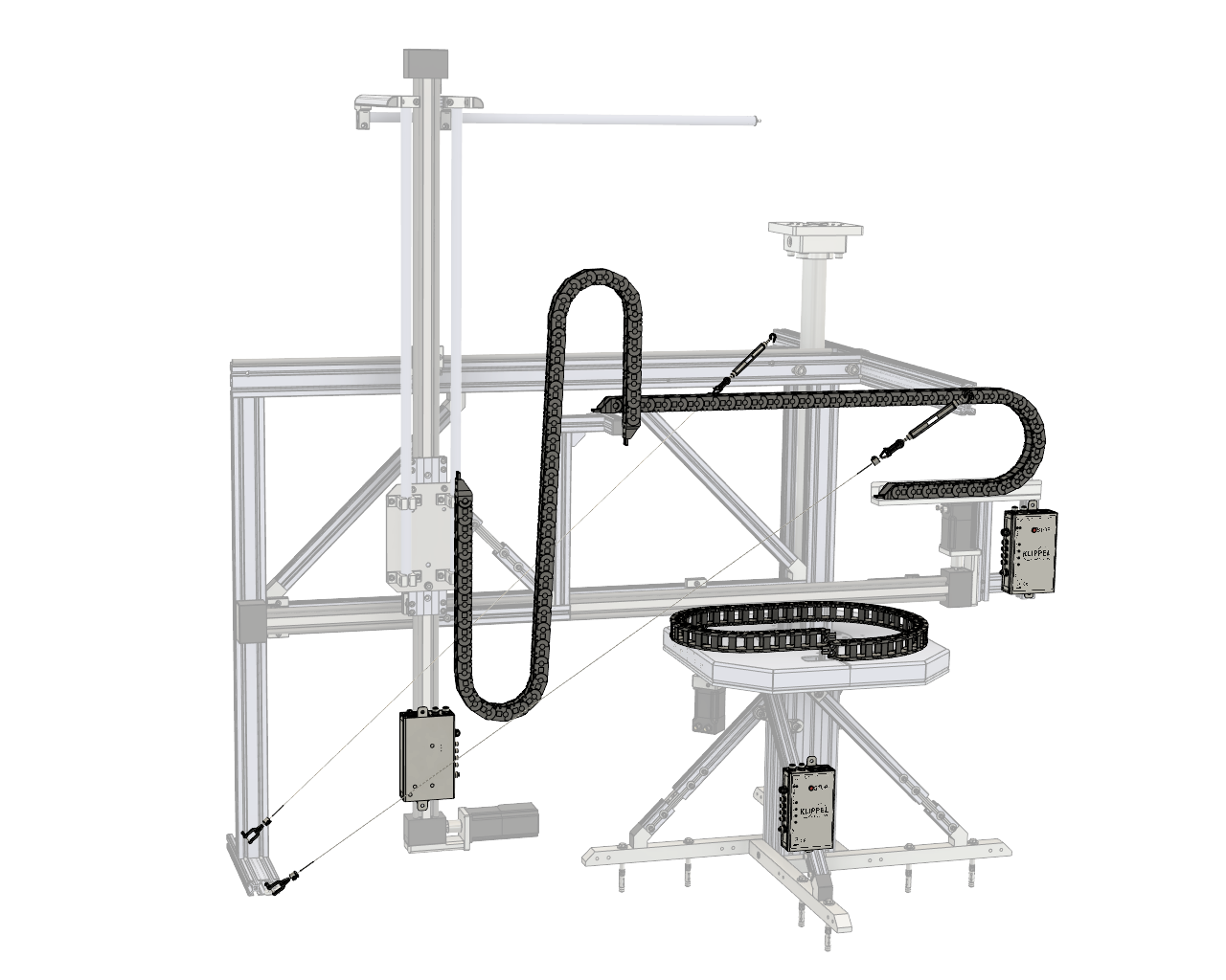
List of parts#
Packet 1#
ID |
Pcs. |
Description |
|---|---|---|
A |
1 |
Phi cable carrier (28x38x1400 mm) |
B |
1 |
R cable carrier (28x38x1820 mm) |
C |
1 |
Z cable carrier (28x28x1240 mm) |
Box 2#
ID |
Pcs. |
Description |
|---|---|---|
D |
2 |
Axis Control (Phi, R) |
Box 3#
ID |
Pcs. |
Description |
|---|---|---|
E |
1 |
Power supply |
Bag 23 (Phi-Axis)#
ID |
Pcs. |
Description |
|---|---|---|
F |
2 |
T-nut M6 |
G |
2 |
Screw M6x10 |
H |
1 |
Phi encoder cable, M12-8p 0.3m |
I |
1 |
Phi motor cable, M12-5p 0.3m |
Bag 24 (R-Axis)#
ID |
Pcs. |
Description |
|---|---|---|
J |
2 |
T-nut M6 |
K |
2 |
Screw M6x10 |
L |
1 |
R encoder cable, M12-8p 0.3m with angled plug |
M |
1 |
R motor cable, M12-5p 0.3m with angled plug |
N |
1 |
Extender cable for limit switch, M8-3p 0.3m |
O |
1 |
Extender cable for limit switch, M8-3p 1.5m |
P |
2 |
Limit switch |
Bag 25 (Z-Axis)#
ID |
Pcs. |
Description |
|---|---|---|
Q |
1 |
Z encoder cable, M12-8p 0.3m with angled plug |
R |
1 |
Z motor cable, M12-5p 0.3m with angled plug |
S |
1 |
Z brake cable, M8-3p 0.3m with angled plug |
T |
1 |
Extension cable for limit switch, M8-3p 2m |
U |
2 |
Limit switch |
Bag 26 (Phi-Axis)#
ID |
Pcs. |
Description |
|---|---|---|
V |
3 |
T-nut M5 |
W |
3 |
Countersunk head screw M5x10 |
Bag 27 (R-Axis)#
ID |
Pcs. |
Description |
|---|---|---|
X |
2 |
T-nut M5 |
Y |
2 |
Countersunk head screw M5x10 |
Z |
2 |
Countersunk head screw M5x16 |
Bag 28 (Z-Axis)#
ID |
Pcs. |
Description |
|---|---|---|
AA |
1 |
T-nut M5 |
BB |
1 |
Countersunk head screw M5x10 |
CC |
2 |
Countersunk head screw M6x10 |
Bag 29#
ID |
Pcs. |
Description |
|---|---|---|
DD |
6 |
Cable bracket (black) |
EE |
20 |
Cable zip tie |
FF |
1 |
Velcro strap |
GG |
8 |
Clip for microphone cable |
HH |
1 |
BNC/XLR adapter (male) |
II |
1 |
BNC/XLR adapter (female) |
JJ |
2 |
Small cable bracket (white) |
KK |
2 |
Low profile head screw M5x10 |
Bag 30#
ID |
Pcs. |
Description |
|---|---|---|
LL |
3 |
End cap for profiles |
Bag 31#
ID |
Pcs. |
Description |
|---|---|---|
MM |
12 |
Cap for 45° connector |
Bag 32#
ID |
Pcs. |
Description |
|---|---|---|
NN |
2 |
Wire rope set |
Bag 33#
ID |
Pcs. |
Description |
|---|---|---|
OO |
1 |
Power supply extension cable, M12-4p 10m |
Bag 34#
ID |
Pcs. |
Description |
|---|---|---|
PP |
1 |
USB/RS485 adapter cable, 1m |
1 |
EtherCON coupling |
|
RR |
1 |
RS485 bus extension cable,EtherCON 10m |
SS |
1 |
Microphone extension cable, XLR 10m |
TT |
1 |
Microphone cable, XLR 2m |
UU |
1 |
Microphone cable, BNC 2m |
VV |
1 |
Microphone cable, BNC 1m |
Bag 35#
ID |
Pcs. |
Description |
|---|---|---|
WW |
1 |
Calibration cone |
Bag 38#
ID |
Pcs. |
Description |
|---|---|---|
XX |
1 |
Screw M6x25 |
YY |
1 |
Calibration cone socket |
Bag 41#
ID |
Pcs. |
Description |
|---|---|---|
ZZ |
1 |
Power Switch Box |
Bag 45#
ID |
Pcs. |
Description |
|---|---|---|
AAA |
1 |
Microphone Collison Sensor |
BBB |
1 |
Microphone Collison Sensor cable |
Mounting instructions#
Important advice: In the following steps the cables of the NFS are installed. Because the NFS can be setup in variable size configurations the cables are sometimes longer than required. Some possibilities to fix the cables at the structure using cable brackets and ties, velcro straps etc. will be shown. The goal is to prevent that any cable gets stuck somewhere while the axes of NFS are moving. Please take care while installing and fixing the cables!
Step 108#
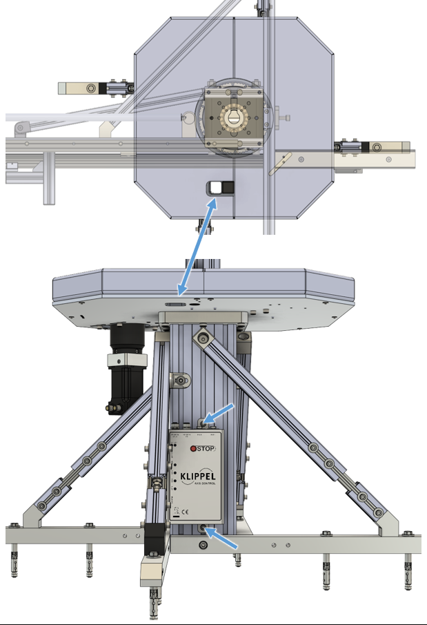
Mount the Phi - Axis Control (D) to the base of the table* below the cable opening in the **table as indicated in the picture with T-nuts (F) and M6 screw (G).
Step 109#
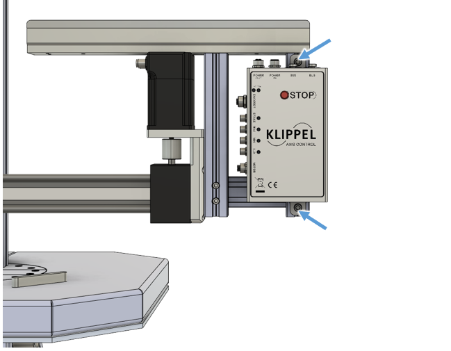
Mount the R - Axis Control using T-nuts (J) with M6 screws (K).
Step 110#
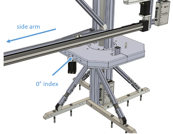
Check that the side arm is directed towards the 0° index on the table as indicated in the picture. If not, gently rotate the side arm to this position by hand.
Step 111#
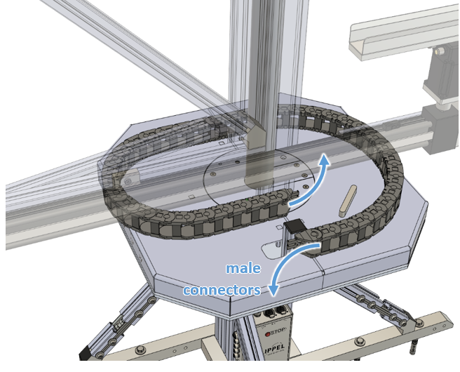
Place the Phi - cable carrier (A) on the table as seen in th picture.
Important:
The cable carrier must be placed exactly as shown. Make sure the male connectors facing towards the outside.
Do not mix up the cable carriers! Phi- and R-carrier slightly differ in length an the orientation of their mounting brackets.
Step 112#
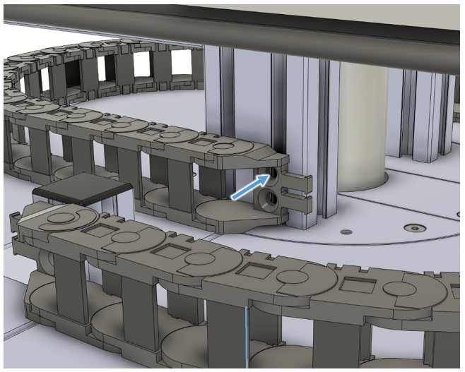
Mount the inner end of the cable carrier to the main profile using M5 countersunk screw (W), a T-nut (V) in the upper hole as indicated in the picture.
Step 113-118#
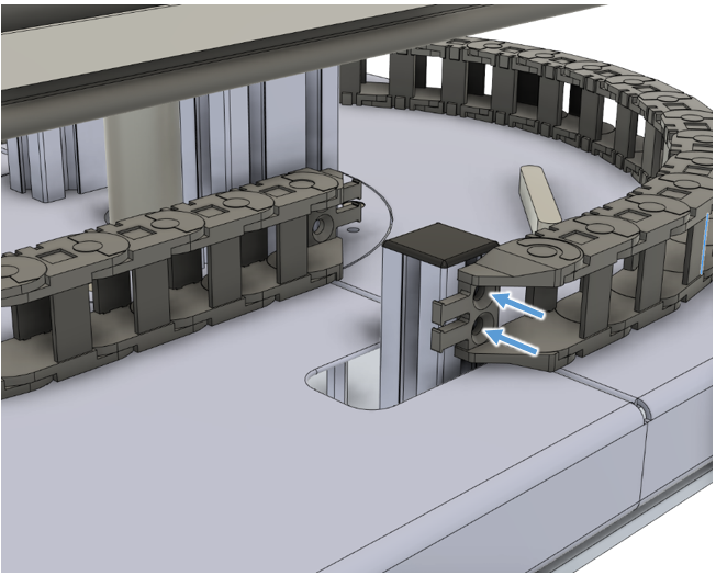
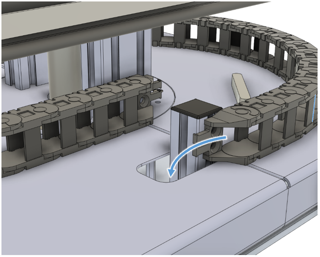
Pull off the end cap of small profile in the table.
Mount the outer end of the Phi - cable carrier to the profile using tw T-nuts (V) and M5 countersunk screws (W).
Slide in the carrier with both T-nuts from the top of the small* **profile.
Tighten the screws when the carrier is lying flat on the table
Push the end cap back on to the profile.
Pull the cables through the opening in the table.
Step 119-124#
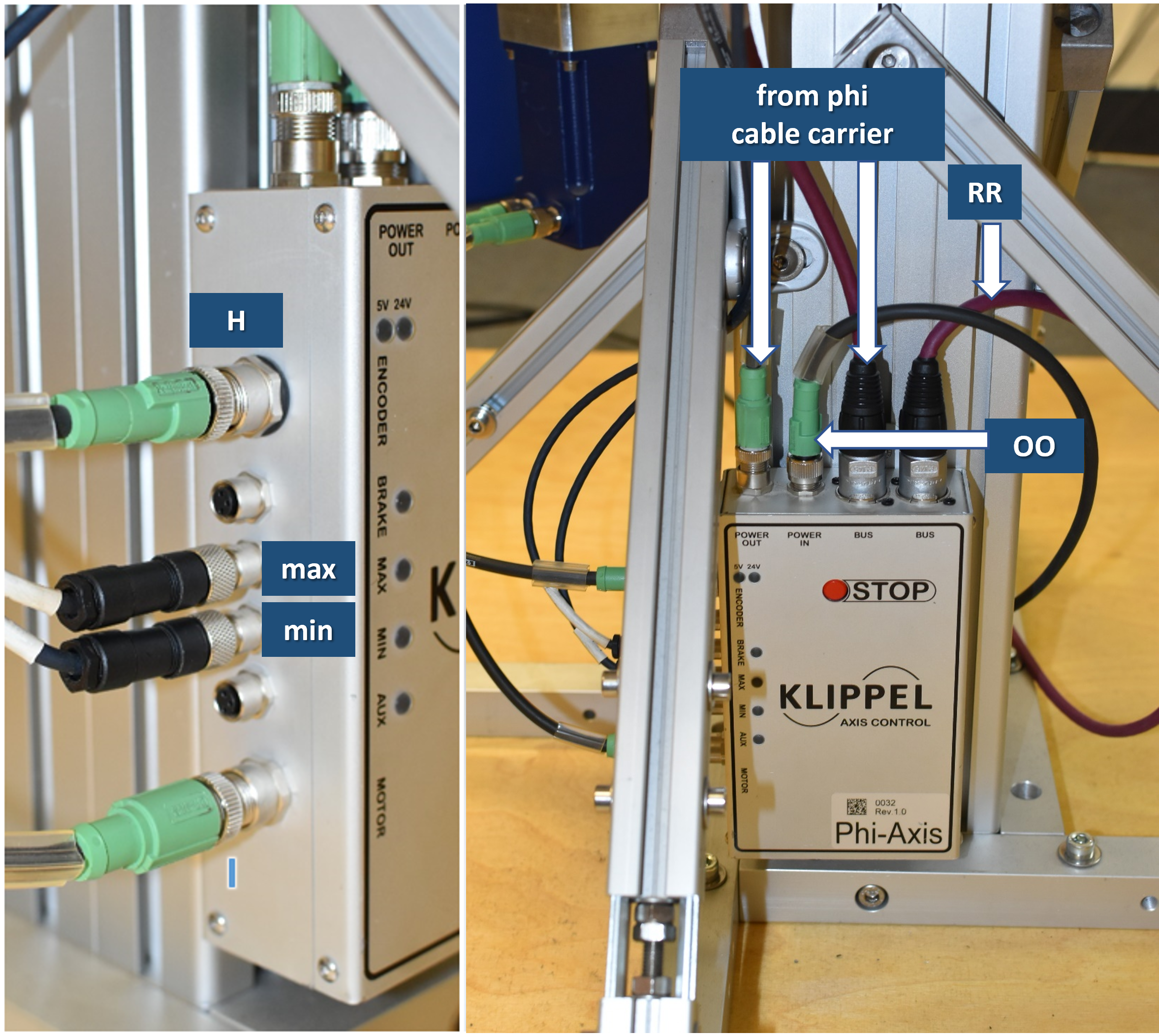
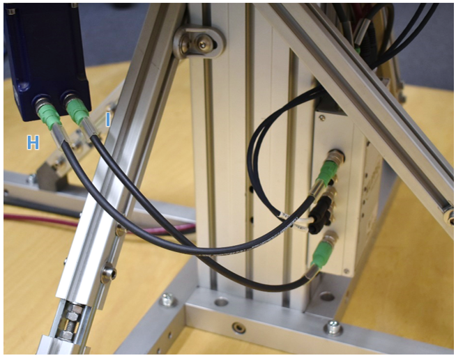
Connect the M12 and EtherCON cables from the Phi - cable carrier to the Phi - Axis Control.
Connect the XLR cable from the Phi - cable carrier to the microphone extension cable (SS).
Connect the power extension (OO) and bus extension (RR) cables to the Phi - Axis Control.
Run the power, bus and microphone extension cables togethe with the loudspeaker extension cable from step 25 towards the measurement PC.
Connect Phi motor (I) and encoder cable (H) between the Phi - motor and the Axis Control.
Connect the MIN and MAX M8-3-pole cables (hardwired to the table) to the identically named connectors on the Axis Control.
Step 125#
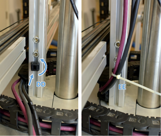
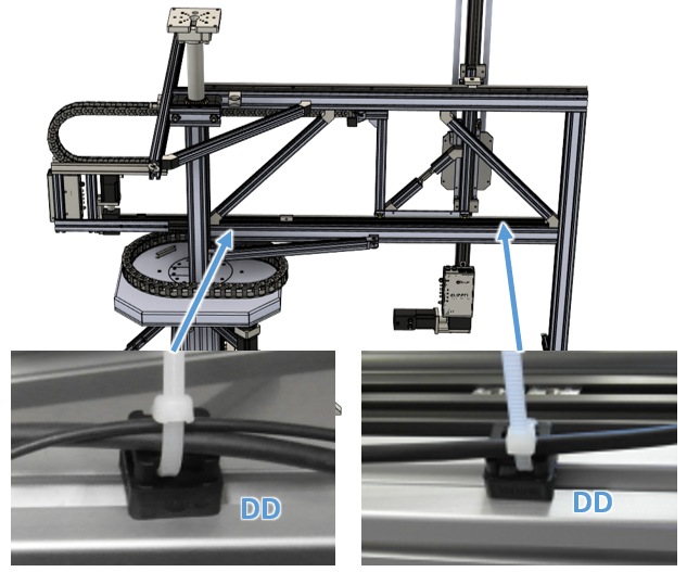
Fix the cables from the inner end of the Phi - cable carrier with a black cable bracket (DD) and a cable tie (EE) as indicated in the pictures.
Step 126#
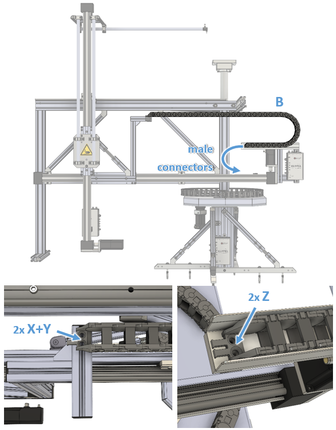
Attach the R-axis cable carrier (B) to the R/Z connector and R axis cable fixture. Use 2x M5x16 screws (Z) on the lower end near the table. Use 2x M5 T-Nut (X) and M5x10 screw (Y) on the upper side.
Important:
Make sure the male connectors face towards the R-Axis-Control
Step 127#
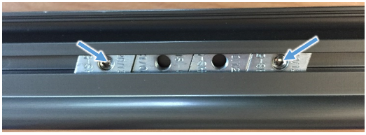
Prepare the R – axis for the limit switch installation by removing the set screws from the slot nuts on the upper side of the axis.
Step 128-129#
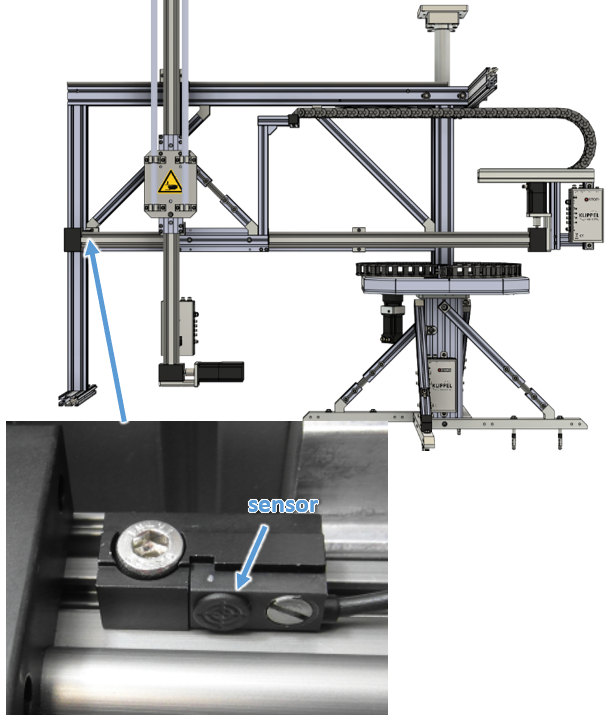
Install the outer limit switch (P) at the end of the R-linear-axis to a prepared slot nut.
Important:
The sensor of all limit switches must face towards rail.
Connect the 1.5 m extension cable (O) to the switch and run it towards the R - Axis Control.
Step 130-131#
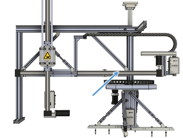
Install the inner limit switch (P) to a prepared slot nut of the R-linear-axis above the table.
Connect the 0.3 m extension cable (N) to the switch and run it towards the R - Axis Control.
Step 132#
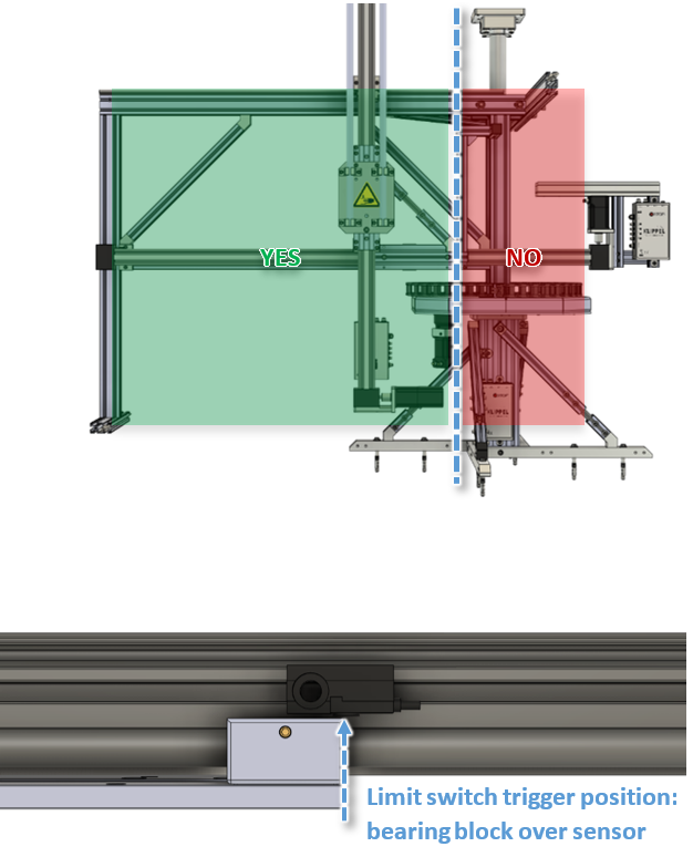
Position the inner limit switch so that it stops the Z – axis before coming into contact with the table.
Check this minimum R position by rotating the side arm gently by hand.
Check that the Z-axis motor does not come into contact with the table legs!
Step 133-135#
Attach the 1.5m extension cable (O) to the outer limit switch.
Attach the 0.3m extension cable (N) to the inner limit switch.
Fix the cables with 2x cable brackets (DD) and ties (EE) on lower horizontal profile of the side arm as indicated in the picture.
Step 136-141#
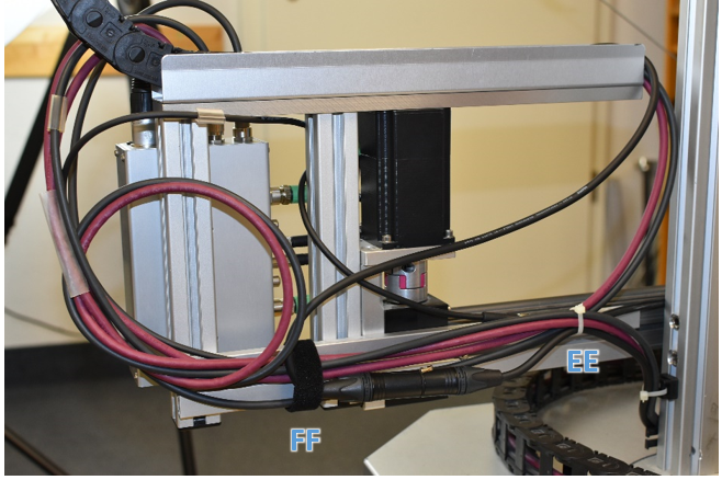
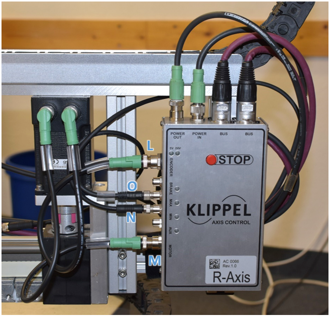
Connect the M12 power and EtherCON bus cables from bot the Phi and the R- cable carrier to the R- Axis Control.
Connect the XLR cable from the Phi - cable carrier to XLR cable* of the **R - cable carrier.
Connect R motor (M) and encoder cable (L) between the R - motor and the Axis Control.
Connect the inner R- limit switch with the 0.3m extension cable (N) to the MIN input of the Axis Control.
Connect the outer R- limit switch with the 1.5m extension cable (O) to the MAX input of the Axis Control.
Loop and fix all cables behind the R – Axis Control with cable ties (EE) or velcro straps (FF) as indicated in th picture.
Step 142#
Prepare the Z – axis for the limit switch installation by removing the set screws from the slot nuts on the left side of the axis.
Step 143#
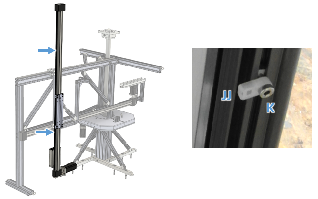
Mount two white cable brackets (JJ) with M5 screws (KK) to the 2 middle slot nuts on the left of the z-linear-axis at the positions indicated in the picture.
Step 144#
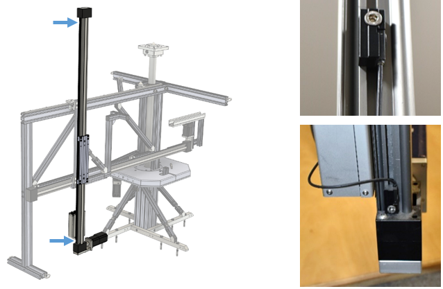
Mount two end switches (U) to the top and bottom slot nuts o the left of the z-linear-axis at the positions indicated in the picture.
Important:
The sensor of all limit switches must face towards rail! (See step 127)
Step 145#
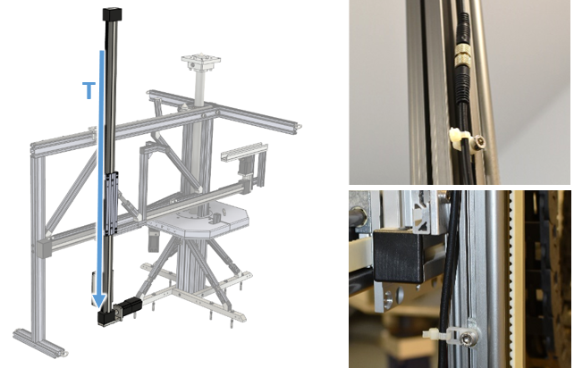
Connect the 2m extension cable (T) to the upper limit switch and fix the cable with 2x zip ties (EE) to the white cable brackets.
Step 146-148#
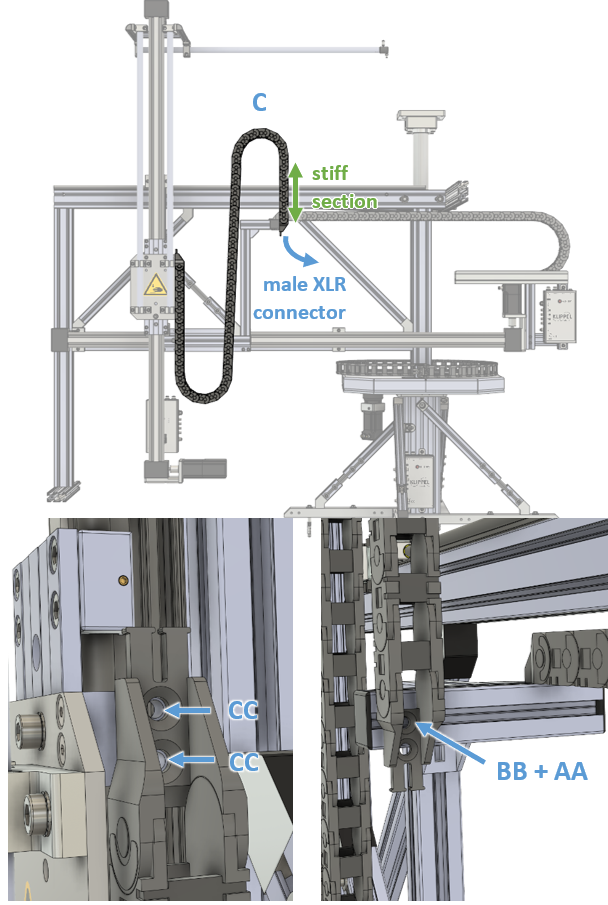
Mount the z-cable-carrier (C) as indicated in the picture, with th stiff section and male XLR connector facing towards the R/Z-connector.
Use two M5x16 screws (CC) to mount the carrier to the clamping plate of the Z-axis.
Use T-nut (AA) / screw** (BB) to mount the carrier to the R/Z-connector.
Step 149#
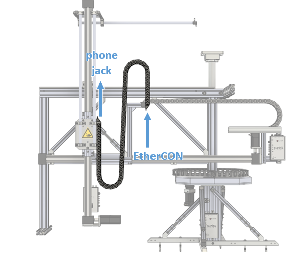
Insert the phone jack of the Microphone Collision Sensor cable (BBB) from the side of the R/Z-connector into Z-cable carrier and manually pull the phone jack through the carrier.
Step 150#
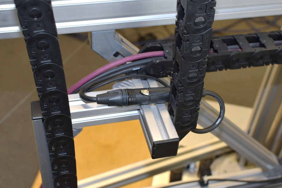
Connect the XLR cables between the R- and Z-cable carrier.
Step 151-153#
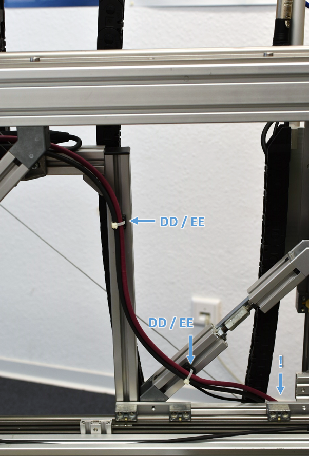
Run the power and bus cables from the R-cable carrier together with the Microphone Collision Sensor cable from the Z-carrier toward the Z-Axis control.
Fix the cables with two cable brackets (DD) and cable ties (EE) on the R/Z connector as indicated in the picture.
Pay attention to the cable routing, especially at the lower end of the R/Z-connector, so that the R-axis can move freely.
Step 154-158#
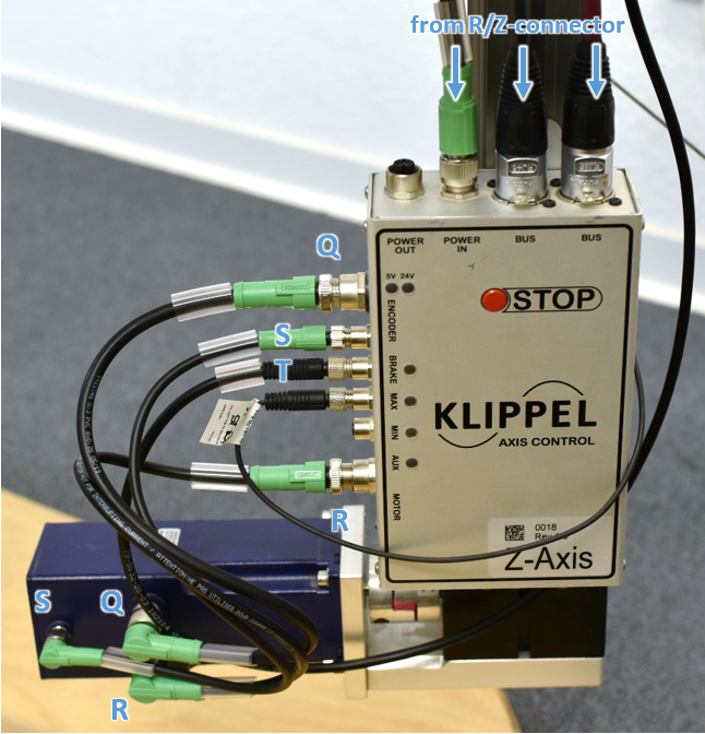
Connect the cables running down from the R/Z connector (Power, Bus and Collision Sensor) to the Z- Axis Control.
Connect the motor (R) and encoder cable (Q) between the Z-motor and Z- Axis Control.
Connect the brake cable (S) between the Z-motor and the BRAKE input of the Z- Axis Control.
157. Connect the upper limit switch with the extension cable (T) to the MAX input of the Z- Axis Control.
Connect the lower limit switch directly to the MIN input of the Z- Axis Control.
Step 159-160#
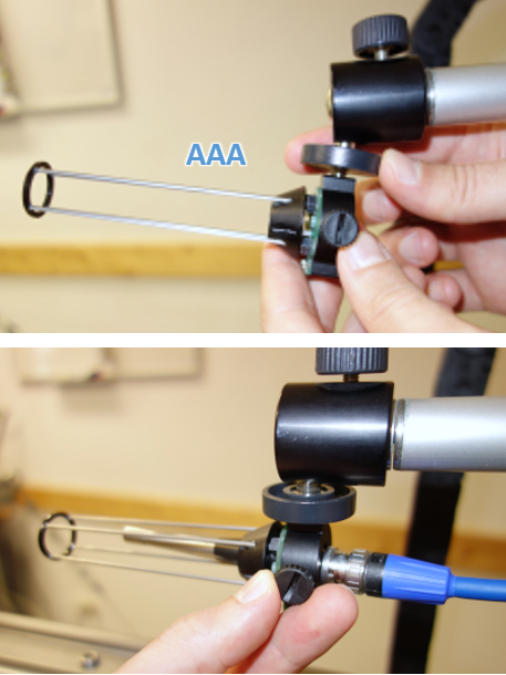
Mount Microphone Collision sensor (AAA) to the ball head at the end of the microphone boom.
Place Microphone into the Collision Sensor and fasten it with th knurled screw.
Step 161-163#
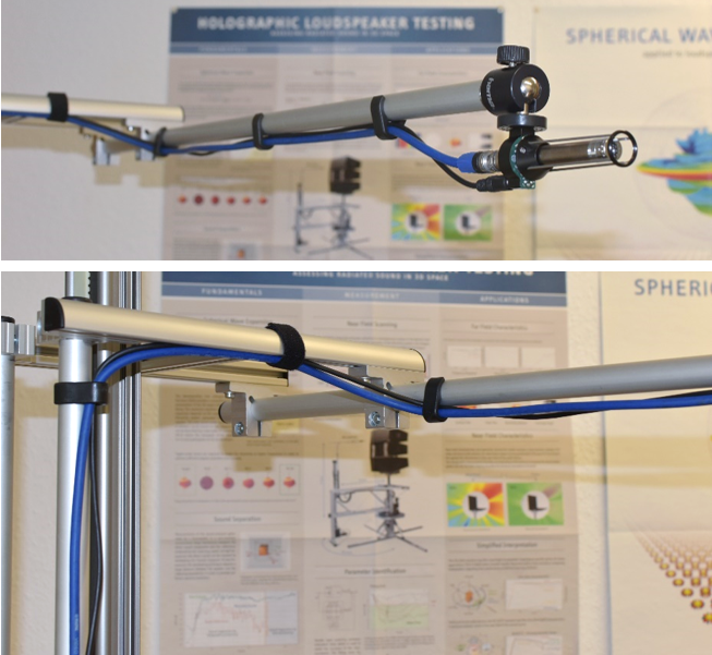
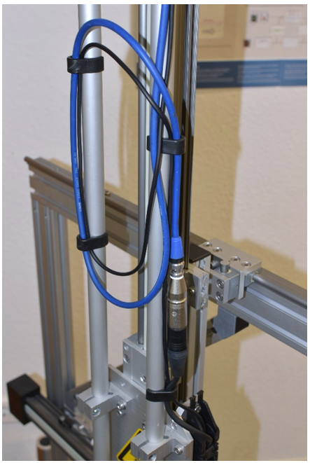
Connect the microphone cable between the XLR cable of the Z-Axis carrier and the microphone.
Connect the collison sensor cable from the Z-Axis carrier to the collision sensor.
Attach both cables to the microphone boom with clips (GG) as shown in the pictures.
Depending on the microphone type the microphone cable can be XLR cable (TT), BNC cable (UU) + adapter (HH), or an integrated cable on the microphone.
Step 164-166#
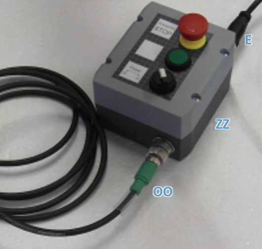
Connect the Power switch box (ZZ) to the power extension cable (OO).
Connect Power supply (E) to the Power switch box.
Place the Power switch box within reach from the Control PC to enable fast access to the red emergency switch.
Step 167#
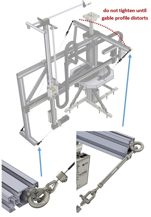
Mount the two wire ropes (NN).
First hang in the hooks of the rope buckles into the rings at both sides of the gable profile.
Second mount the shackles on the other side of the ropes to the rings of the lower small profile of the side arm.
Third turn the buckles to bring both wire ropes to equal and light tension.
Do not overtighten the ropes! When the gable profile visibly distorts the ropes are too tight.
Step 168#
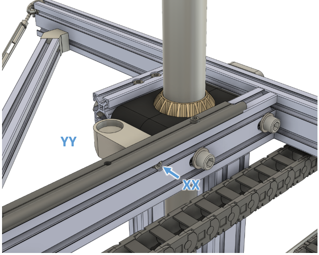
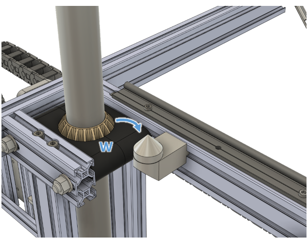
Attach the calibration cone socket (YY) to the upper side ar profile with M6x25 screw (XX) and place the calibratio cone (WW) in the socket.
Adjustment Procedure#
The adjustment is a critical part of the hardware setup. Precise adjustment is required so that the individual axes of the NFS form a cylinder coordinate system. The specified accuracy of the measurement equipment is only achieved after the full adjustment procedure.
The adjustment steps must be done one after another in the following order:
Main Tube inclination
Side Arm inclination
Z-Axis inclination in R-Axis direction
Z-Axis inclination in φ-Axis direction
Main Tube Inclination#
During the installation of the NFS the tube inclination is already adjusted with steps 29 to 35 . The following steps 169 to 179 can therefore be skipped on a first-time setup and are only required for later checks or when the NFS is relocated.
Step 169-171#
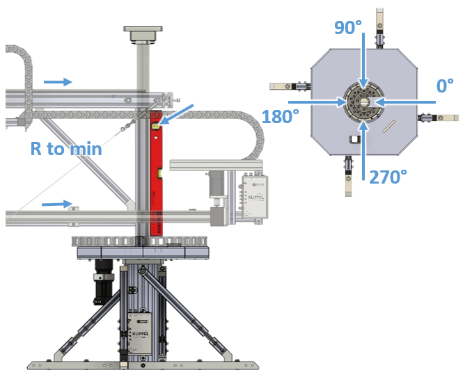
Manually move the R-Axis to its minimum position.
Check the inclination of the main tube by placing the spirit level directly on the main tube on the opposing side to the side arm.
Rotate theside arm to all 4 shown orientations to check inclination.
Step 172-174#
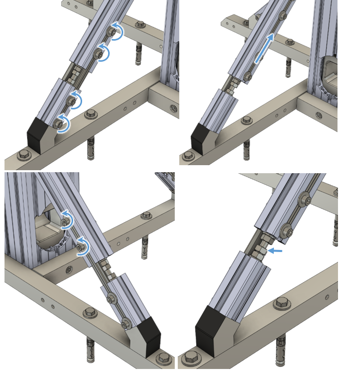
If the main tube is not vertically level according to the spirit level, i all 4 side arm orientations, adjustment is necessary:
Loosen all 4 screws on the right profile connector and all 4 legs and slide the connector upwards.
Loosen the upper 2 screws on the left profile connector and all 4 legs.
Loosen the counter nuts (nut 2) on all 4 leg braces.
Step 175#
Adjust the tension of the upper nut 1 on two opposing cross brace to adjust the incline of the main tube as shown in the example picture.
Attention: Always decrease the tension of the nut on one brace before increasing the tension of the opposite brace.
Step 176-177#
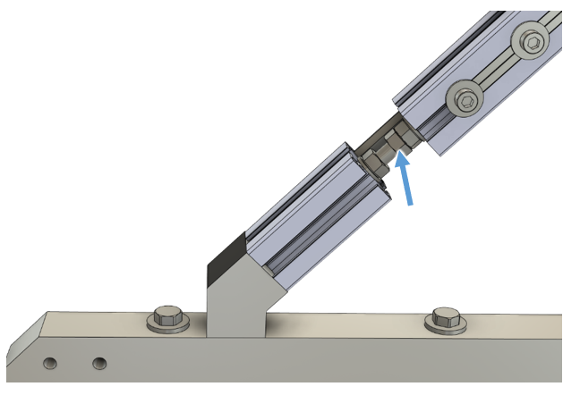
After adjusting the incline of the main tube, counter the upper nut of each cross brace with the second nut 2.
Use a second 13 mm combination wrench to tighten nut 2 while holding nut 1 with the first wrench.
Step 178-179#
Slide the right profile connector inside each cross brace back dow into the brace stumps.
Tighten all screws in all of the 8 profile connectors on all of th 4 legs.
Side Arm Inclination#
Step 180-181#
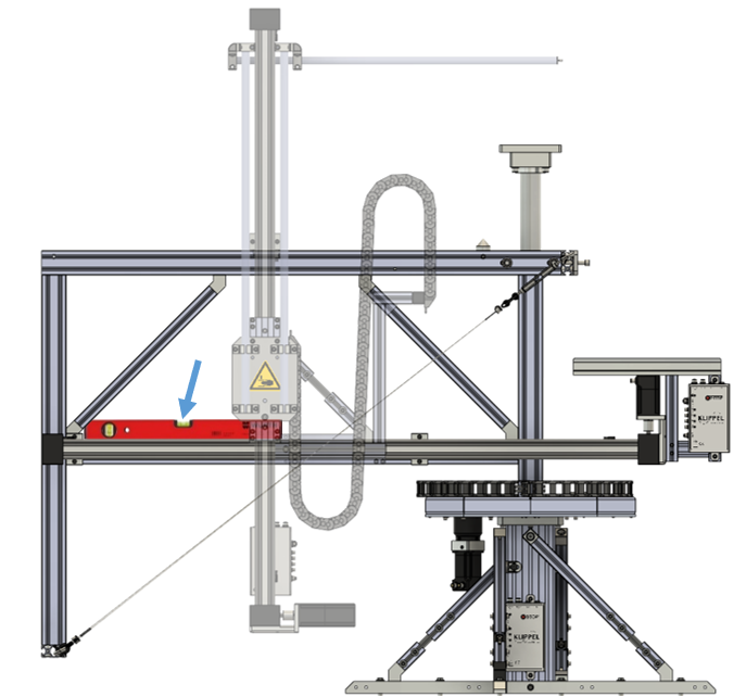
Move R-Axis approximately to the center of its travel between MAX and MIN.
Measure the inclination of the side arm by placing the spirit level* on the flat surface of the **R-axis.
Step 182-184#
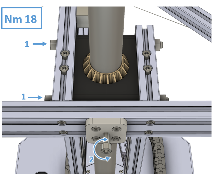
If the side arm is not horizontally level according to the spirit level, adjustment is necessary:
Loosen the large screws (1) in the pillow block bearing.
Adjust the small screw (2) on the pillow block bearing until the side arm is level.
After adjusting, tighten the large screws (1) in the pillow block bearing with the torque wrench to 18 Nm. (Counter the nuts with the 19mm wrench)
Z-Axis Inclination Adjustment (R-Axis-Direction)#
Step 185-186#
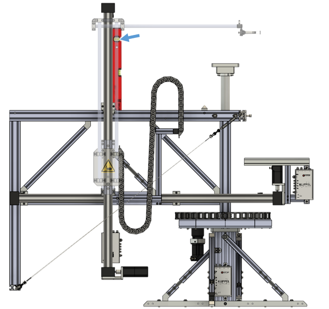
Move the R-Axis approximately to the center of its travel between MAX and MIN.
Measure the inclination of the Z-axis by placing the spirit level on the flat surface on the inner side the Z-axis.
Step 187-188#
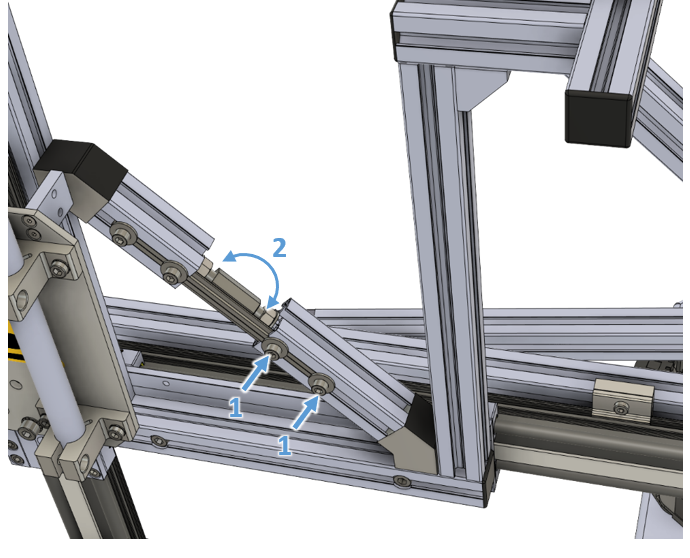
If the Z-axis is not vertically level according to the spirit level, adjustment is necessary:
Loosen the 2 indicated screws (1) on profile connector of the R/Z-connector and adjust long center nut (1) until the target valu is reached.
After adjusting, tighten the screws (1) of the profile connector again.
Z-Axis Inclination Adjustment (φ -Axis-Direction)#
Step 189-191#
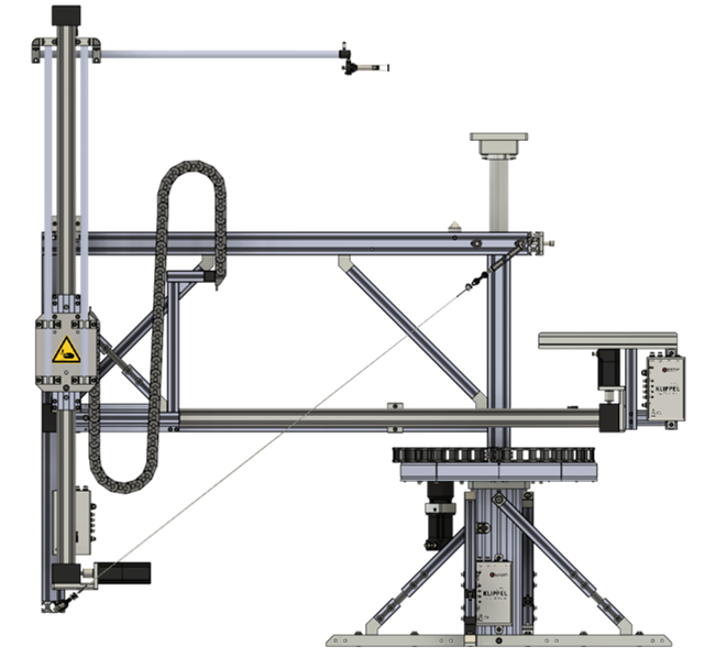
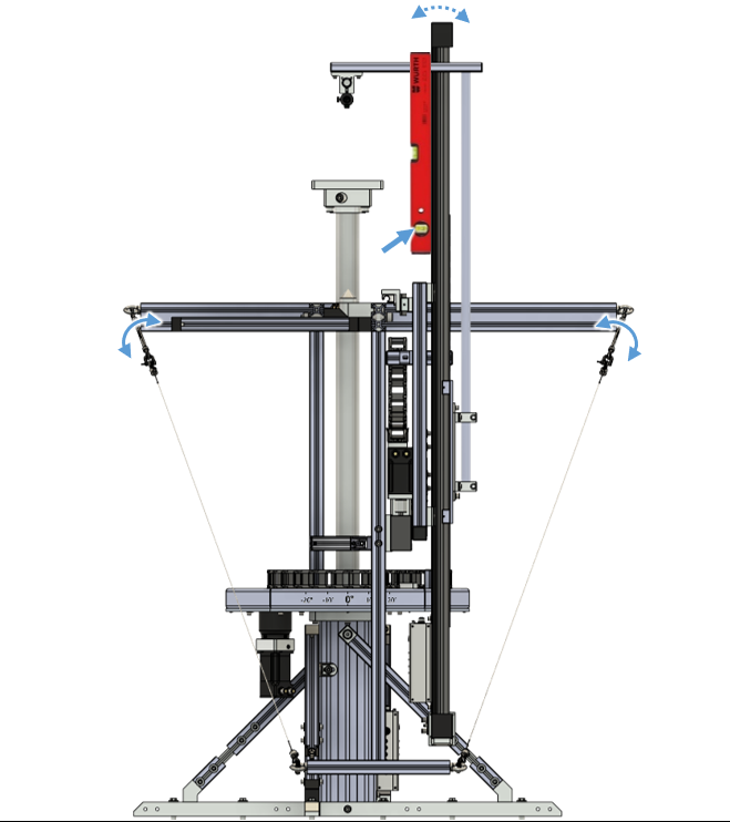
Move R-Axis approximately to the outer end of its travel MAX.
Measure the inclination of the Z-axis by placing the spirit level on the flat back surface off the Z-axis.
If the Z-axis is not vertically level according to the spirit level, adjustment is necessary:
Adjust the Z-axis level with the tension of the steel ropes, by turning the buckles on the top end of the ropes.
Do not overtighten the ropes! When the gable profile visibly distorts the tension is too high.
Setup area preparations / security signs#
List of parts#
Bag 43#
ID |
Pcs. |
Description |
|---|---|---|
A |
1 |
Floor marking tape |
B |
1 |
NFS Security sign |
Bag 44#
ID |
Pcs. |
Description |
|---|---|---|
C |
1 |
Floor sticker “No Entry” |
Mounting instructions#
Step 192 - 194#
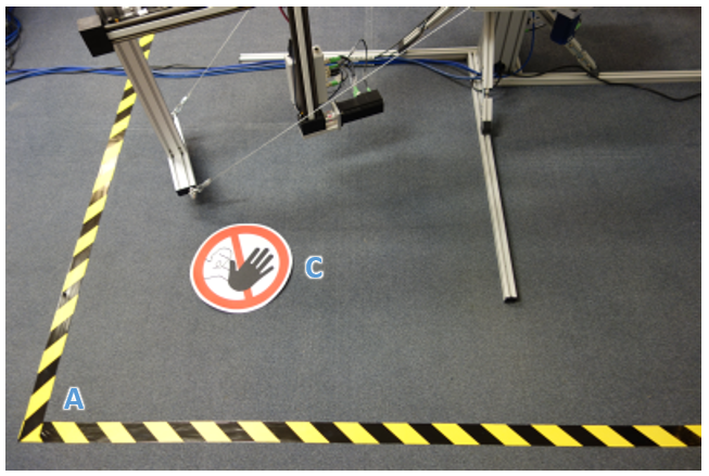
Use the Floor marking tape (A) to mark the area of movement of the NFS. Mark a full square around the device.
Place the floor sticker (C) on the floor, so that it is immediately visible when entering the room.
Provide additional precautions when necessary to ensure that no unauthorized personnel may enter the area of movement during operation.
Step 195#
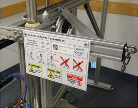
Loosen the screws on the NFS Security sign (B) and mount it to the face of the gable profile as shown in the picture.
Step 196#
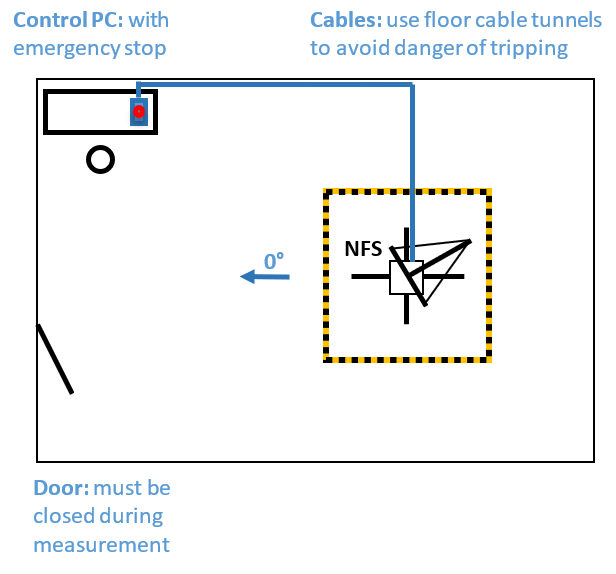
Example setup:
Position the Power Switch Box in reach of the PC used to control the NFS.
Step 197#
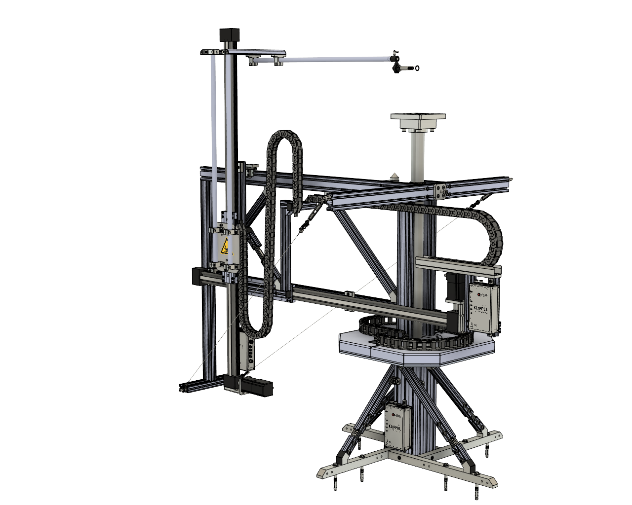
Assembly complete!
Please see the NFS – Near Field Scanner manual, to prepare for your first measurement.
Document Version#
Current Version#
Document Revision: v4
For NFS Hardware Revision: Rev 1.09
Revision Log#
- v1
- 24.11.2021Initial document revision for NFS HW Rev 1.09
- v2
- 03.01.2021Fixed formatting issues
- v3
- 13.07.2022Page 47: typo in bag number fixed. Slot nuts and screws are in bag 25
- v4
- 12.06.2026Step 2: Instruction added for the usage of the M8 washers (D) from bag 2Step 51: Instruction improved for avoiding wrong mounting of the rotary disk (V)
