
KCS Monitor#
KCS Monitor Tutorial#
Introduction#
Klippel Controlled Sound is an adaptive software solution featuring nonlinear speaker control, active speaker protection, linear and nonlinear distortion reduction, automatic system alignment and much more. KCS Monitor is a software module running in the Klippel dB-Lab framework which is used for interacting with this technology. It enables communication with supported KCS hardware platforms and is used to both set up the KCS real-time processing software and to read comprehensive diagnostics information from it.
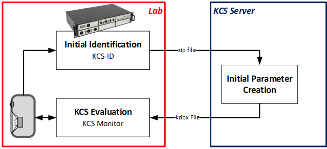
To control a loudspeaker with KCS, initial KCS data describing the particular speaker type (transducer model, enclosure type and volume) is required. This KCS initial dataset will be stored in KCS Monitor operations. Find information about creating initial data in KCS-ID – Parameter Identification.
Two versions of KCS Monitor are available:
KCS Monitor
KCS Monitor Pro
The standard version, KCS Monitor, does not require a hardware-dongle and supports all KCS hardware platforms except the Klippel Analyzer 3 (KA3). The KA3 platform is intended for advanced evaluation cases, if extensive customizations for the KCS setup are needed or long-term tests have to be performed. In this case, the KCS Monitor Pro module - which requires a license - has to be used. KCS Monitor Pro also features side-by-side comparison of modelled and laser-measured diaphragm displacement.
Requirements#
KCS hardware platform
Klippel dB-Lab version >= 210.918
KCS initial data, gathered from measuring the speaker assembly (transducer and enclosure) with KCS-ID and uploading the result to the KCS Server (Klippel GmbH or a Klippel partner company can support you in this process). The KCS server will generate a KCS Monitor Operation holding the KCS initial data. From KCS Monitor it can be uploaded to the KCS hardware platform and can be stored there permanently if desired (see standalone operation).
Nuvoton A6 version >= 3.00 (only NAD - Nuvoton Audio Development platform)
Hardware Setup#
Setup the KCS target hardware platform for KCS on-line processing.
KCS running on KA3: See section Hardware Setup - KA3. Make sure that your audio source is connected to the IN1/2 XLR plug
KCS running on NAD: Refer to section Hardware Setup - Nuvoton or the NAD Quick Start Guide provided by Nuvoton. Make sure that the output audio device on your PC is set to Nuvoton Audio Development Platform.
KCS running on Klippel APE Evaluation Board: see corresponding user manual.
Note
- Before powering up the hardware, ensure
correct polarity of the speaker connection to the KCS hardware platform
that the used power supply is providing sufficient and appropriate voltage
that you are using KCS initial data measured on an identical speaker type
Polarity Check#
Correct polarity is vital for KCS. The speaker must be connected with the same polarity that was used during the KCS-ID measurement. To avoid confusion, KLIPPEL recommends following the polarity definition used in dB-Lab software modules: A positive DC voltage should move the voice coil outwards (away from the back plate). You might check the polarity using a battery with a small DC voltage of 1…1.5 V.
Standalone Operation#
KCS hardware platforms are capable of standalone operation, i.e. the KCS algorithm can be executed without an active connection to a PC. The KCS initial data and device setup can be stored on the hardware device permanently (using the option Store Initial KCS Data in Flash in the property page of KCS Monitor). In such case, KCS processing can be started automatically on power-up. NAD boards that are acquired bundled with reference speakers are often delivered in this state. Another way to put KCS hardware in standalone mode is starting KCS online processing from KCS Monitor and then detaching from the KCS hardware device without terminating KCS processing there. If the KCS initial data is not explicitly written to the hardware device flash, then KCS parameters will be available only until the hardware device is powered off.
Tutorial 1 – Starting KCS#
Open Initial KCS data#
Initial KCS data comprising speaker and target platform parameters is required to start KCS:
Use the KCS-ID module (KA3 device required) and download the according KCS Monitor operation from the KCS Server (see KCS-ID – Parameter Identification).
If you are using a NAD board as KCS target platform and you have received a reference speaker together with the hardware, initial KCS data for this speaker is provided by Nuvoton.
Open the Klippel dB-Lab database comprising the KCS Monitor operation holding the initial KCS data belonging to your speaker. If the hardware device is already running in standalone mode, you can instead download the KCS initial data and setup parameters from the hardware device into an empty KCS Monitor operation. This process is described below in section Connecting to the Hardware Device. To create an empty KCS Monitor operation, open a dB-Lab database in dB-Lab or create a new one, then choose Edit > New Operation and select KCS Monitor.
Connecting and uploading KCS Data to the Hardware Device#
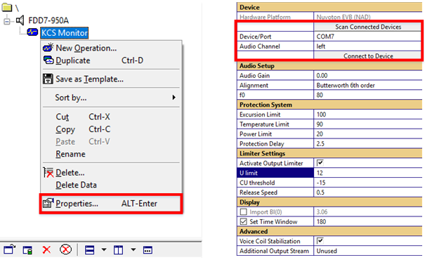
Open the property page of KCS Monitor by right-clicking on the operation and selecting Properties in the context- menu or marking the operation and pressing Alt + Return.
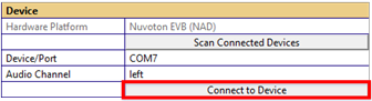
For KCS platforms connected via a serial port (e.g. NAD), press Scan Connected Devices to update the available COM ports.
Within the properties window, press Connect to Device to synchronize the KCS setup of software module and hardware. For multichannel hardware devices, select the desired Audio Channel first. Every instance of dB-Lab can only connect to one audio channel at a time. You could open several instances in parallel though, but this might notably reduce the responsiveness of the interface. Refer to Troubleshooting in case of any issues.
When trying to connect to a device that is running in standalone mode, you will be notified that KCS processing is already running on the hardware device. You can then decide whether you want to attach to the running KCS processing. If you choose yes, this will download the data from the hardware and store it in the KCS Monitor operation that you are trying to connect from. This will overwrite all data that was previously stored in the operation. If you want to keep a copy of your previous data, duplicate the operation before connecting.
Starting KCS on-line processing#
Start the KCS real-time processing by pressing  in the toolbar. This will start the audio
output and the collection of diagnostic data. In case any errors or warnings appear, see
Troubleshooting.
in the toolbar. This will start the audio
output and the collection of diagnostic data. In case any errors or warnings appear, see
Troubleshooting.
Note
(only applicable if KA3 is used) The KCS Monitor Pro operation sets the KA3 routing independently from the KA3 Signal Configuration to be able to run R&D or QC operations in parallel. Hence, you do not set any routing in the dB-Lab by yourself. In addition, never change the KA3 Signal Configuration while KCS is running on the KA3 device. This will bypass KCS and might harm the speaker and your hearing.
Play Audio#
You can now verify that everything is connected correctly by playing music or other audio signals.
While playing audio signals, you can observe loudspeaker states and parameters (see Tutorial 2 - Viewing data), evaluate the KCS performance by switching KCS on and off (see Tutorial 3 – Switching Control Modes) and perform measurements (see guidelines in KCS Evaluation Tutorials). If any issues occur, see Troubleshooting.
Note
The main benefits of KCS are experienced at high voice coil excursion. Apply a bass boost (alignment) for achieving best bass performance and for driving the speaker to its physical limits (see Tutorial 4 – Alignment and Equalization).
Stopping KCS on-line processing#
The KCS Monitor operation can be terminated by pressing the green check mark in the toolbar. After finishing, a message box ‘Terminate KCS on-line Processing?’ pops up. If the option “no” is chosen, KCS on-line processing will continue to run on the hardware in standalone mode without a PC connection.
Tutorial 2 - Viewing data#
KCS continuously monitors loudspeaker parameters and compensates the effects of ageing, fatigue, temperature changes and humidity. During the execution of KCS Monitor, diagnostic data such as time-variant loudspeaker parameters and states are constantly uploaded from the KCS hardware platform.
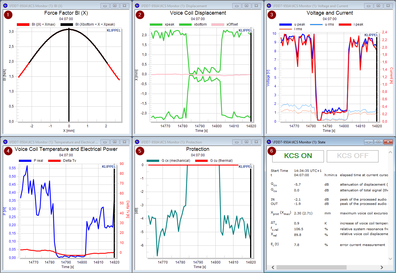
Default windows and most important on-line diagnostic information (see Reference - Result Windows for more detailed documentation):
Force Factor Bl(x) – Force factor Bl over the entire displacement range covered during the last second (black curve) and covering the whole identified working range [-xmax, xmax] (red curve).
Voice Coil Displacement – The green curves represent the predicted maximum positive and negative peak displacement. The pink curve indicates the voice coil’s rest position which should be close to zero if the DC Stabilization is turned on. In case the KA3 is used, peak and bottom laser signals are displayed here as well. The fat red curves shows the current excursion limit xprot used by the mechanical protection system. In this graph, colored background shading will indicate whether KCS was currently ON (light green shading) or OFF/OFF+EQ (light red shading).
Voltage and Current – Peak and RMS voltage and current.
Voice Coil Temperature and Electrical Power – Voice coil temperature (based on both measurement and simulation) and measured electrical power.
Protection – This window shows the degree of activation of the thermal (Gcu - red) and mechanical (Gcx - green) protection systems.
State Table – This table shows important state information and warnings of the KCS processing. Buttons for switching KCS on and off are available in this window.
Note
Time Cursor
In all windows where the x-axis denotes the measurement time, a bold black time cursor is located at the far right. This time cursor can be dragged using the mouse or be moved by clicking into the chart while holding Ctrl.
When you move the time cursor you see the other windows getting updated to reflect the state of the device under test (DUT) at the selected time. This allows to review all the recorded history data and parameter variances over time.
Display is delayed KCS Monitor reads out data from the hardware device once every second. You will experience a delay of a few seconds before an event is displayed on the screen. This delay will be larger when monitoring several channels simultaneously in separate instances of dB-Lab.
Tutorial 3 – Switching Control Modes#
KCS can be switched on and off using the according buttons in the State window during runtime. See descriptions below.

KCS ON (Nonlinear Control): Full Nonlinear Control with active protection, distortion compensation, linear and nonlinear inductance compensation and voice coil stabilization. System alignment is applied.
KCS OFF+EQ (Equalization only): No mechanical protection and no nonlinear distortion compensation. Time-variant parameters and the linear inductance are compensated. System alignment is applied.
KCS OFF (Bypass Control): No alignment, no mechanical protection and no distortion compensation. The thermal protection is still active.
Warning
The transducer can be destroyed in KCS OFF modes as the mechanical protection system is switched off! When switching to these modes from KCS ON mode, make sure that the mechanical protection system is not active.
Note
Switching the control modes on multi-channel hardware devices via the KCS Monitor will affect all channels. So switching the control mode on one channel will force the other channel to the same mode. This results in the following effects: * Starting the second channel from KCS Monitor will force the first channel into KCS ON mode, to keep the modes synchronously. * Starting the second channel will mute the whole device until both channels are running. * Controlling only one channel from outside the KCS Monitor might lead to unwanted behavior, as it will break the synchronism between the channels.
Tutorial 4 – Alignment and Equalization#
This tutorial describes how to tune the small signal response of the KCS speaker system.

The automatic alignment allows to tune the low frequency response of the system to a desired transfer function with defined cut-off frequency f0 and filter type (such as Butterworth or Chebychev). Due to the adaptive compensation of time-varying speaker parameters, this transfer function will be maintained over the whole lifetime of the transducer. The alignment is used to
apply a bass boost to a sealed box system shifting the cut-off frequency 1-2 octaves below the system resonance frequency fc
match an arbitrary speaker to a given sealed or vented box enclosure and achieve your desired transfer behavior
reduce voice coil excursion below cut-off frequency (subsonic filter)
Any additional equalization can be applied before the KCS processing, e.g. using Nuvoton’s A6 tool (NAD platform only).
Tips and Requirements for Setting Alignments#
NAD evaluation board only: Boosting low frequencies leads to large gains in the alignment filters. To avoid clipping, the input signal must be attenuated by the maximum alignment filter gain manually to avoid clipping.
Lowering the cut-off frequency by far more than one octave (sealed systems) or far below port/enclosure resonance (vented/passive radiator systems) is not recommended due to the potentially drastic increase of peak voltage and displacement demands.
To prevent low-frequency content from causing displacement and consuming power without significant sound pressure contribution, it is highly recommended to select at least a 4th (sealed box) or 6th (vented/passive radiator) order alignment.
Find more detailed information and theory about the alignment filters under Reference - Alignment.
How to set an Alignment#
Connect the KCS hardware and open the KCS Monitor operation including initial data for the particular speaker. Connect to the device to be able to change KCS setup parameters on the KCS Monitor’s property page. KCS must not be running on the device yet.
Choose a desired transfer behavior (e.g. Butterworth 6th order) and a low cut-off frequency (e.g. half of the system resonance frequency found in the window Linear Speaker Parameters). You can see the desired transfer function by opening the window H(f) Sound Pressure.

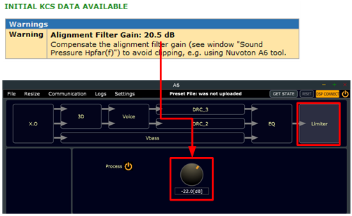
(NAD platform only) Compensate the alignment gain to avoid clipping:
Start the Nuvoton A6 tool.
In A6, connect to the device via Communication UART (Mutex). Select the same COM port as set in the KCS Monitor.
Go to the Limiter category and set the limiter gain in the A6-Tool to compensate for the alignment gain. Example: If dB-Lab displays an alignment filter gain of 20.5 dB, set the limiter gain in the A6-tool to -21 dB (Note the minus sign!)
Run
the KCS Monitor operation and start playing music and/or test signals.
Equalization#
After the alignment is applied in dB-Lab, the overall frequency response can be adjusted by using the A6 tool (NAD platforms only) or other external tuning software running on the PC or another hardware. It is recommended to use the Klippel QC system for measuring the frequency response. See document KCS Evaluation Tutorials.
Warning
(A6 tool only) Make sure to not only compensate the maximum gain of the alignment as explained above, but also the maximum equalizer gain of the A6 EQ category if it exceeds 0 dB total gain. This is essential to avoid the A6 limiter getting triggered.
Tutorial 5 – Protection and Limiter#
KCS is dedicated to operate loudspeakers in the large signal domain and drive them close to their physical limits. Therefore, it must comprise protection systems to avoid any damage. The states to be monitored and limited are excursion, peak voltage, temperature and electrical power. The values of these limits depend on the target platform, the target amplifier, the speaker and limits specified in the KCS-ID measurement module. Default values are set automatically on the KCS Server. However, some of these limits might have to be adjusted manually. This tutorial explains briefly how the protection systems and the limiter works and how to adjust the respective parameters.

Short Theory#
Mechanical Protection System#
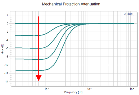
If the anticipated peak displacement is about to exceed the mechanical limit, the low-frequency signal components in the audio signal are attenuated by an adaptive linear filter.
The advantage of using an adaptive linear filter is that it does not produce nonlinear distortion, like a limiter would. Even in the moment of activation, minimum artifacts are produced, especially if some look-ahead delay is applied.
Thermal Protection System#
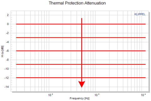
If the voice coil temperature is about to exceed the thermal limit, the complete audio signal will be attenuated for a short time.
Voltage Limiter#
The output voltage limiter is the last element in the KCS processing chain. It is intended to avoid amplifier clipping. If KCS detects a higher output voltage than the specified maximum voltage U limit, the limiter acts in the following order:
1. First, the limiter activates the mechanical protection system (adaptive high-pass filter). Many speakers have low efficiency at low frequencies, so that temporarily attenuating these signal components can reduce the peak voltage. The maximum allowable attenuation of low frequencies can be specified in the setting Maximum Cx activation. Set it to zero to deactivate this feature.
2. If the output voltage is still too high after step 1, the limiter also triggers the thermal protection system, which reduces the overall audio gain. The maximum allowable value can be specified in setting Maximum Cu activation. Set it to zero to deactivate this feature.
3. (Firmware version >= 1006.180) If the output voltage is still too high after step 2, the signal is compressed so that the output does not exceed U limit.
An optional Look-ahead delay (Firmware version >= 1006.180) can be specified to reduce artifacts from the attack of the limiter.
The Release Speed defines the protection system deactivation speed in dB/s.
Note
(only if Firmware version < 1006.180) Due to the fast attack of the limiter, a short audible artifact might be produced. In a frequency sweep measurement, this would be detected as impulsive distortion.
How to set up Protection and Limiter#
See also
See KCS Evaluation Tutorials for tutorials on how to perform impulsive distortion measurements and How to Treat Rub & Buzz Issues.
Excursion Limit#
There are several reasons why the maximum excursion might be reduced in KCS Monitor.
1. Transducer produces Impulsive Distortion#
Xmax is the displacement range where the speaker can be operated safely without producing irregular distortion (Rub&Buzz etc). Xmax is determined during KCS-ID using an imported target excursion value and using an IDR (Impulsive Distortion Ratio) measurement. If the results of the IDR measurement are not meaningful, this can cause incorrect values for the estimation of Xmax.
If the IDR limit in KCS-ID was set too low or was deactivated, a too large value for Xmax could be estimated. Furthermore, the measurement is not very sensitive for certain irregular distortion such as air flow noise.
If audible impulsive or other irregular distortion (e.g. Rub&Buzz) is produced by the transducer during evaluation (subjective and objective tests), reducing the Excursion Limit can increase sound quality.
2. Amplifier is not sufficient#
If the maximum excursion Xmax set by KCS-ID/KCS Server cannot be reached with the used amplifier due to insufficient peak voltage, the voltage limiter will activate frequently to avoid amplifier clipping. A limiter can degrade the perceived sound quality due to its inherent nonlinear behavior. Therefore it can be beneficial to avoid limiter activation.
If a significant bass boost is applied (maximum gain > 10 dB) on systems intended for reproducing broadband stimuli, a major part of the available amplifier voltage is used at low frequencies. In such case, consider changing the system tuning so that less peak voltage is required by either
Reducing the Excursion Limit xprot.
Increasing the Alignment Frequency f0, using a high order alignment filter (steep rolloff)
Good indications showing that the amplifier is not sufficient for achieving xmax is that
‘KCS Output Limiter active’ message in the State window pops up regularly
u out peak in the Voltage and Current window is regularly reaching the U limit value
displacement is always significantly (>10 %) lower than the protection limit xprot indicated by the bold red lines in the Displacement window, even when the amplifier voltage is at its limits
Note that the inverse case (available xmax not being sufficient for your application) cannot be solved by setting the relative excursion limit in KCS Monitor larger than 100 %. The nonlinear parameters have been measured only for displacement ranges up to xmax and cannot reliably be extrapolated to larger excursions. Instead, re-run KCS-ID with adjusted settings for this speaker. See KCS-ID – Parameter Identification for details.
Thermal Protection#
A conservative default limit is set automatically on the KCS Server. Anyway, make sure that it is below the maximum rating of your transducer. Note that the limit value is a temperature increase in the unit Kelvin, referenced to the temperature during the KCS-ID measurement. It should be adjusted if better values are provided by the transducer manufacturer. Anyhow, choose a conservative value as the voice coil heats up nonhomogeneously, but the thermal protection relies on an average coil temperature.
Output Voltage Limiter#
Default values for the limiter are set automatically on the KCS Server if the maximum voltage of the power amplifier is known, for instance the KA3’s AMP card, the APE evaluation board and the NAD platform. In this case usually the limiter setup parameters do not have to be changed. However, in some cases manual adjustments as described in the passages below might increase the system’s performance:
If a strong bass boost is performed (>12 dB maximum gain), the major part of the total voltage is used at low frequencies for broad-band signals. Then Maximum Cx activation can be set to a high negative value (-6 … -15 dB) and the limiter will mainly attenuate low frequencies. If no significant bass boost is performed (<6 dB maximum alignment gain), Maximum Cx activation should be set to approx. -3 dB … -6 dB.
The Maximum Cu activation (firmware >= 1006.180) has to be relatively small (approx. -3 dB) because a significant modulation of the overall gain will be perceived as unpleasant pumping effect.
The audio system should not be used with the voltage limiter being active all the time as this might degrade audio quality. For improved sound quality, it is better to reduce peak voltage requirements. See section Excursion Limit above for guidance.
Note
(firmware >= 1006.180) See the Protection window to check the activation level of the limiter. Reduce peak voltage requirements, use a stronger amplifier or a more sensitive transducer if the limiter is active very regularly by a significant amount (depending on application, G limiter < -3…-12 dB).
(firmware < 1006.180) The limiter activation is indicated by a warning ‘KCS Output Limiter active’ popping up for a short time in the State window.
Note
Make sure that the specified limiter voltage U limit is at least about 1V lower than the rail voltage of the amplifier as provided by the power-supply and - if applicable - boost converter.
Protection with separate ANC input channel#
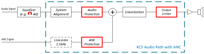
On certain special KCS configurations a dedicated input channel for active noise cancellation (ANC) is available. For example, the Nuvoton NAU83G60 has this feature built in. In ANC applications, the latency of the signal has to be minimized in order to reach the desired cancellation effect.
The ANC signal is provided to KCS via a separate input channel to avoid unnecessary digital filters (EQ / Alignment) adding group delay to the signal. Also, a dedicated speaker protection system for ANC is used with ultra-short latency (0.1 ms) while the audio protection system has a larger, configurable latency to minimize audible artifacts.
Note
The fixed low-pass filter in the ANC Signal is only available upon special request and is preferably applied externally prior to any KCS processing. The currently implemented 4th order Butterworth filter at 1.5 kHz adds 0.3 ms group delay to the ANC processing.
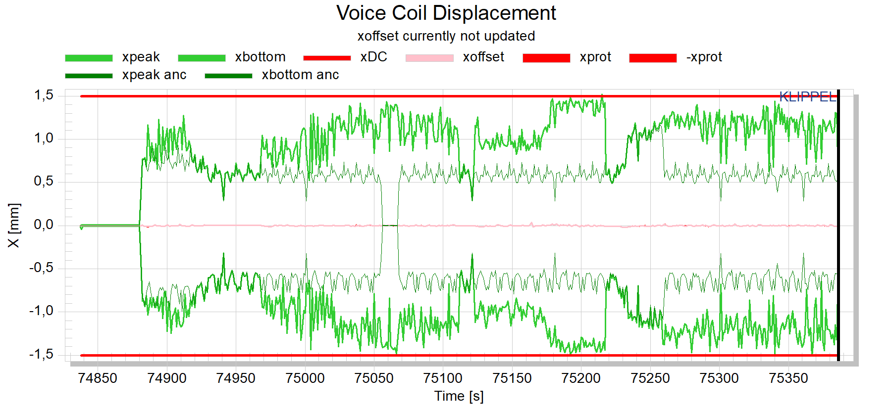
Right-click inside the voice coil displacement chart and select Show All Curves to see the separate displacement caused by the ANC input signal only. The ANC displacement budget can be adjusted. In below example, it is fixed to 70 % of the available displacement working range (xprot).
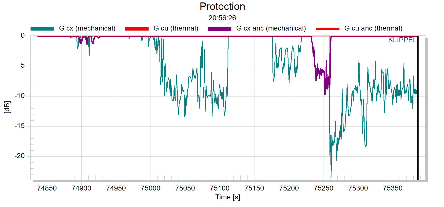
In the Protection Chart, the audio and the ANC signal attenuation gains are shown separately. If the assigned ANC budget is exhausted, the ANC protection is activated.
Note
As the ANC protection is configured for ultra-short latency (0.1 ms), the attack of the protection attenuation could produce audible artifacts. It is recommended to avoid activating the protection of the ANC signal by adjustment of the respective ANC system used (G cx anc should stay at 0 dB).
If the assigned ANC budget is not completely used, the remaining displacement working range is available for audio reproduction.
Note
Contact KLIPPEL support in order to discuss and optimize the strategy for ANC protection in context of a particular ANC over-all system design.
KCS Monitor Reference#
KCS Setup Parameters#
This section describes the available parameters to change the KCS setup. These parameters can be found in the Properties of the KCS Monitor operation. See the simplified signal flow charts and setup parameter descriptions below.
Signal Flow – KA3#
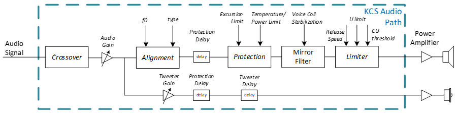
Signal Flow – NAD platform#

KCS Processing – Setup Parameters#
Note that not all parameters are available on every hardware platform.
Audio Gain#
Change the gain at the input stage of the KCS real-time processing.
Relative Tweeter Gain#
Change the gain of the tweeter channel relative to the woofer channel. Note that the Audio Gain changes the level of both woofer and tweeter channel.
Tweeter Delay#
Adjust the delay of the tweeter channel relative the woofer channel delay.
Crossover#
Choose a crossover filter from the drop-down list if the speaker under control shall only be used up to a certain frequency or if a tweeter channel shall be used. Important: If the target bandwidth in the KCS-ID was not set to fullrange, the KCS Server will automatically apply a crossover filter. In this case, the crossover frequency cannot be increased, as the speaker parameters were not identified above this frequency.
Alignment#
Define a new target frequency response. Based on the initial KCS data, a pre-filter is calculated automatically to achieve a target response with 2nd, 4th or 6th order high-pass characteristic with a desired cut-off frequency f0. See Alignment for more information.
Excursion Limit#
The initial parameter identification (KCS-ID and KCS Server) defines a certain excursion limit xmax. In some cases this value might be too high because the amplifier’s peak voltage is not sufficient or impulsive distortion is audible. See Tutorial 5 – Protection and Limiter for more information.
Temperature Limit#
This defines the temperature at which the thermal protection reduces the overall audio gain by G cu. The temperature limit value is defined as a temperature increase in Kelvin. 0 Kelvin corresponds to the temperature at which the initial identification (KCS-ID) was performed.
Power Limit#
If the electrical power is about to exceed this limit, the thermal protection system is activated and reduces the overall gain for a short time. Note that the power limit is not required for speaker protection and can be set to an arbitrarily high value. The transducer is sufficiently protected by the mechanical and thermal protection system. The power limit might be however used for limiting the amplifier power.
Protection Delay#
A delay of the audio signal in the mechanical protection system is applied to reduce audible artifacts caused by protection system activation.
Limiter Settings#
The output voltage limiter is intended to avoid amplifier clipping. If a higher output voltage than the specified maximum voltage U limit is detected, the limiter activates the mechanical protection system which applies an adaptive high-pass filter. If the mechanical protection is attenuating low frequencies by more than the absolute value of Maximum Cx activation, the thermal protection system which reduces the overall gain is activated additionally until the Maximum Cu activation range is reached. The Release Speed defines the deactivation speed of the protection systems when activated by the limiter in dB/s.
In firmware versions >= 1006.180, additionally, a compressor can be triggered after the capabilities of above countermeasures are exhausted. The Look ahead delay is used to minimize artifacts of the limiter compression attack. See Tutorial 5 – Protection and Limiter for detailed descriptions how to set up the limiter.
Voice Coil Stabilization#
With active voice coil stabilization, a small DC voltage will be applied to keep the voice coil always at its initial rest position. The stabilization should always be active. However, it can be useful to deactivate it to for demo and evaluation purposes.
Store Initial KCS Data in Flash/Clear Flash#
On some hardware platforms like the APE Evaluation Board or all NAD platforms, the initial KCS data may be stored in persistent memory to allow standalone operation. When persistent data is available, KCS will automatically start when powering the hardware - a PC connection is not required. For using this feature, KCS Monitor must be connected to the device and KCS must not be running. Note that there is only one initial data slot. Storing another data set will overwrite an already stored set. On NAD platforms, persistent setups are part of the firmware. Contact smartamp@nuvoton.com for assistance.
KCS Monitor – Display Parameters#
Import Bl(0)#
Bl(0) is the transduction factor between electrical current and mechanical force at the rest position x=0. KCS Monitor needs this value for calibrating relative digital KCS parameters into the physical domain. This allows to display the voice coil displacement in mm and mechanical stiffness in N/mm, instead of using the dimensionless relative parameters X/Xmax and Kms (x) / Kms (x=0). The value of Bl(0) is identified on the KCS Server if a laser was used in the KCS-ID measurement or if a Bl(0) was specified in the KCS-ID. If no mechanical calibration was done on the KCS Server, Bl(0) is empty and only relative parameters are displayed.
Set Time Window#
Limit the number of history records which are displayed in all charts with time x-axis. One history record corresponds to one second.
History Memory#
Set the number of history records which should be stored in the operation. It is not available in the standard KCS Monitor version, which stores always 30 minutes of data.
KCS Monitor Demo View#
This activates the non-pro KCS Monitor look which might be preferred when doing demos.
Reset Laser Position#
(KCS Monitor Pro only) Reset the laser signal back to the zero-position.
Result Windows#
This section explains the content of the different result windows. The result windows have a lot of similarities to the LSI3 windows.
Nonlinear Curves#
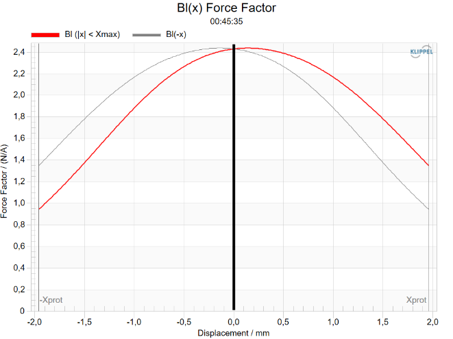
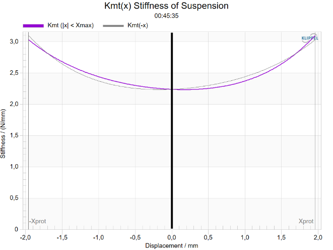
See LSI3 – Large Signal Identification for information about the nonlinear curves such as Bl(x) and Kms(x).
x(t) Displacement#
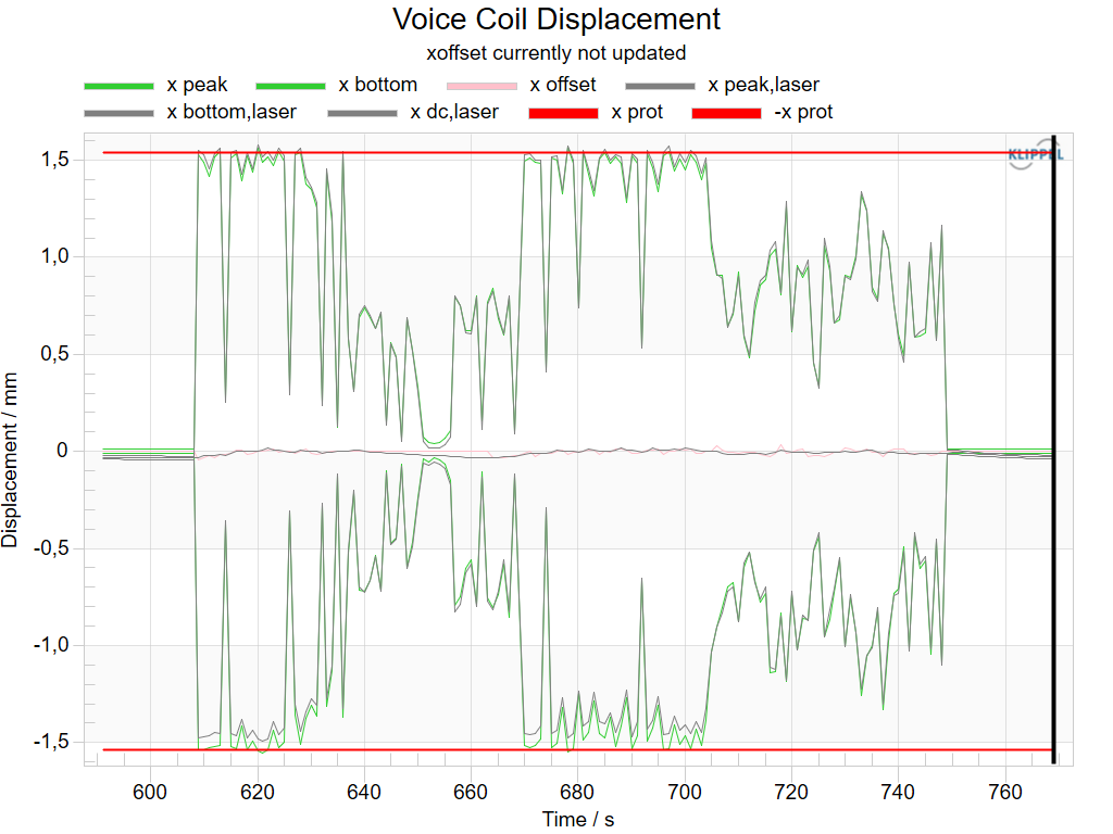
The window Displacement shows the absolute voice coil displacement over time. This information is e.g. important for evaluating the functionality of the mechanical protection system. The green curves represent the positive and negative peak displacement.
The control system also identifies voice coil rest position changes due to nonlinear parameters, visco-elastic effects, a leaky box or other reasons which is essential for realizing a reliable mechanical protection system. Voice coil rest position changes are indicated by the x offset curve. Note that if the DC Stabilization is active, this curve should be close to zero at any time. The above diagram originates from KCS Monitor Pro which offers side-by-side display of laser measurement data. The curves relating to laser measurement are not visible in the standard version of KCS Monitor.
u(t) Voltage, i(t) Current#
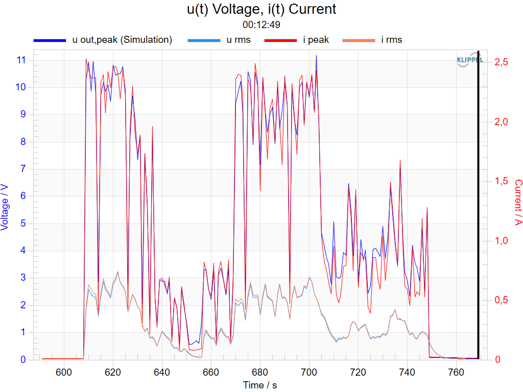
The voltage and current signals are essential for dimensioning a proper amplifier for the particular application. For amplifier evaluation, it is very useful to evaluate the peak values of voltage and current with different signals (e.g. different music signals, speech) and different alignments for verifying that the amplifier is sufficiently dimensioned, esp. in regards to peak voltage capability. For real audio signals such as music and speech which comprise a high crest factor, the peak voltage and current is usually the limiting factor of the amplifier.
The curves u rms, u peak (hidden curve), i peak and i rms are signals which are measured by the sensors in the hardware device. These signals are not recorded in full audio sampling frequency but are low-pass filtered and decimated (usually to 6 or 12 kHz, see Sampling Frequency Detector in Setup) to lower DSP processing requirements. Hence if higher frequencies are reproduced, these signals can comprise a significant error.
The u out peak (sim) curve shows the peak voltage at the output of the KCS processing at full audio sampling frequency, multiplied with the gain between its output and the amplifier output. This value represents the output voltage of the amplifier very accurately if
the gain of the amplifier is constant (which is a requirement for KCS processing anyway) and
the amplifier can provide the simulated voltage without clipping. The latter can be avoided by activating the KCS output limiter. (See Tutorial 5 – Protection and Limiter)
∆Tv(t)Temperature, P(t) Power#
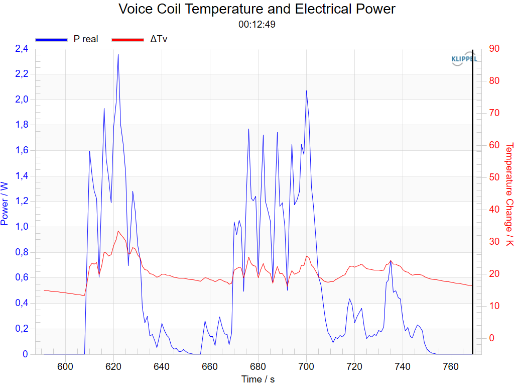
This window shows the increase of the voice coil temperature ∆Tv and the electric input power P(t) versus time. This information is very helpful to verify that the transducer’s power handling and the amplifier dimensioning is sufficient.
fs(t) Resonance Frequency#
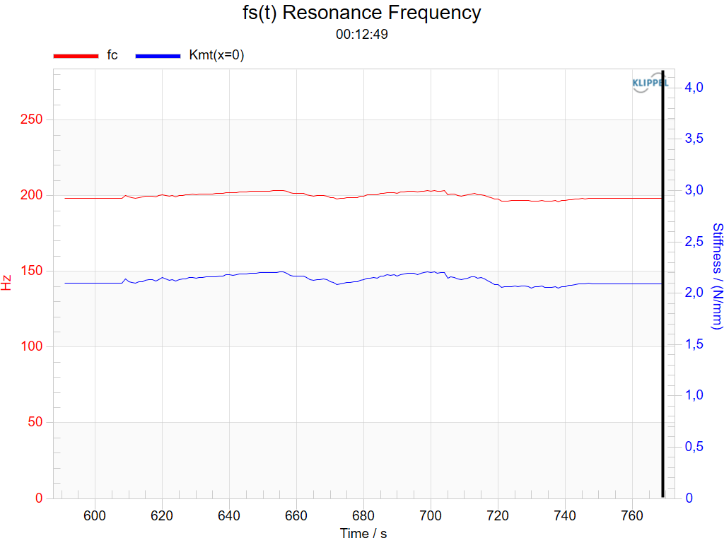
This result window shows the speaker’s resonance frequency fs(t, x=0) or fc(t, x=0), the stiffness of the mechanical suspension Kms (t, x=0) or Kmt (t, x=0) at the rest position x = 0.
At high excursions the mechanical stiffness Kms (and hence the resonance frequency) at the rest position usually decreases. The information shown in this window quantifies the degree of time-variance of the parameters of the particular DUT with a particular stimulus.
Note that the identified parameter changes are compensated by Nonlinear Control. Hence the variations do not have any impact on the frequency response of the KCS active speaker system.
Distortion Components#
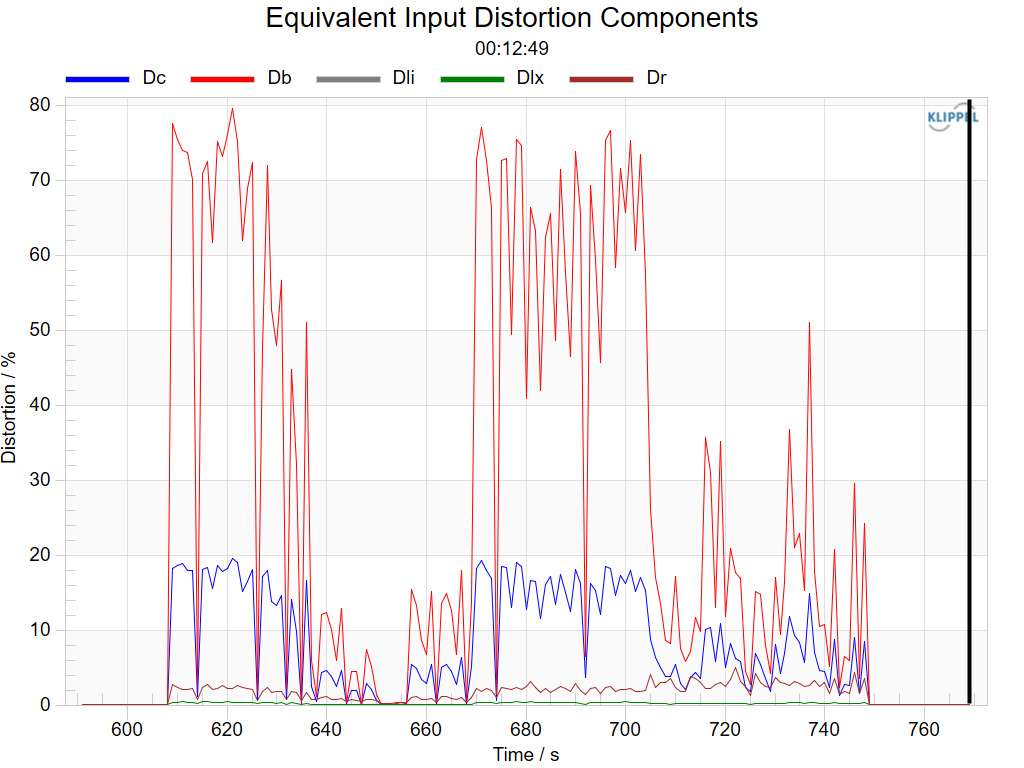
The relative distortion components describe the ratio of the peak values of the equivalent input distortion generated by the selected nonlinearities and the peak value of the total signal.
The equivalent input distortion is identical to the voltage that is required to compensate the particular nonlinearity. The curves show distortion originating from:
Dc = suspension stiffness variation over displacement
Db = motor strengh variation over displacement
Dli = inductance variation as a function of electrical current
Dlx = inductance variation as a function of displacement
Dr = resistivity variation as a function of velocity
Z(f,x=0) Impedance Magnitude#
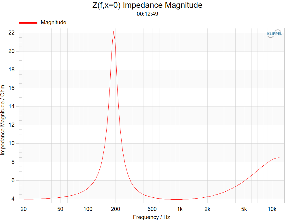
The impedance magnitude is calculated based on the identified linear speaker parameters.
Protection#
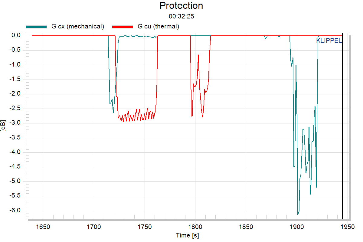
The activation of the mechanical and thermal protection systems can be observed at any time. The attenuation value G cx (mechanical) indicates an approximate value at which degree low frequencies are attenuated by the mechanical protection system. The attenuation value G cu (thermal) indicates the attenuation value of how much the whole audio signal is attenuated due to temperature/power protection.
Only firmware >= 1006.180: G limiter shows the total activation of the limiter. G limiter is composed of the components G cx (limiter), G cu (limiter) and G limiter (out). The latter curves are hidden by default but can be made visible by right-clicking in the chart and activate Show All Curves. See more information in the tutorial Tutorial 5 – Protection and Limiter.
You can view the absolute displacement curve over time for evaluating the functionality of the mechanical protection system. The voice coil temperature can be observed in the window Electrical Power and Temperature.
H(f) Sound Pressure#
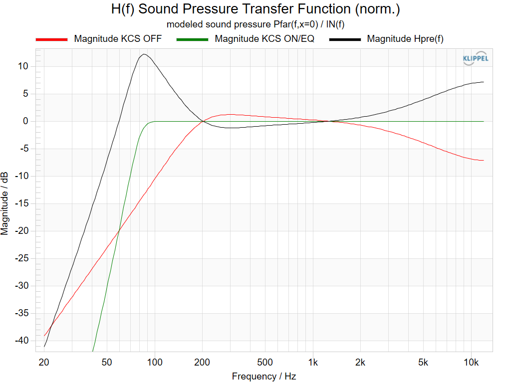
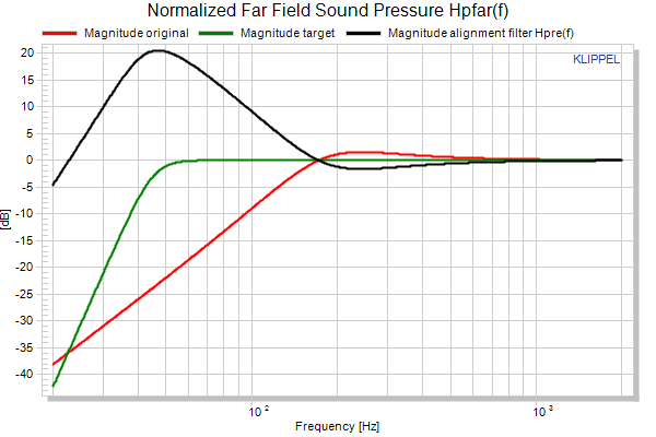
This window shows the predicted small signal sound pressure transfer function of the target system before and after applying the pre filter Hpre(f), which contains a linear alignment filter and a linear inductance compensation filter. The speaker’s transfer function is calculated based on the lumped parameter model used by KCS. Note that this model is only valid at low frequencies where the wavelength is siginificantly higher than the transducer dimensions. Hence, e.g. mechanical modes above the fundamental one are not considered. The transfer functions are normalized so that a gain of 0 dB at high frequencies is reached for a virtual loudspeaker system without inductance. See Tutorial 4 – Alignment and Equalization and Alignment for detailed information.
Magnitude/Phase KCS OFF (original)
Relative sound pressure transfer function P(f)/Stimulus(f) of the pure identified driver without any filtering
Magnitude/Phase KCS ON/EQ (target)
Relative target sound pressure transfer function P(f)/Stimulus(f) including alignment, crossover and linear inductance compensation.
Magnitude/Phase (instantaneous)
Relative instantaneous target sound pressure transfer function P(f)/Stimulus(f) including alignment, crossover, linear inductance compensation and the protection system, if applicable in the selceted KCS mode (ON/OFF/EQ). This curve is time-variant and can change with cursor position, depending on the activation of the protection systems G cx (mechanical, limiter) and G cu (thermal, limiter).
Magnitude/Phase Fixed Point
If fixed point arithmetic is used for the filter implementation (e.g. on NAD platform), this curve displays the realizable transfer function with the given coefficient accuracy. A warning is displayed on the KCS Monitor’s Properties if the curve differs significantly from the target.
Magnitude/Phase Hpre(f)
Combined filter transfer function to realize the target transfer function, including - alignment filter - inductance compensation - compensation of time variant behavior, such as changes of DC resistance and resonance frequency
Linear Speaker Parameters#
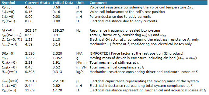
This table shows the speaker’s linear parameters at the cursor position and of the initial data.
State#
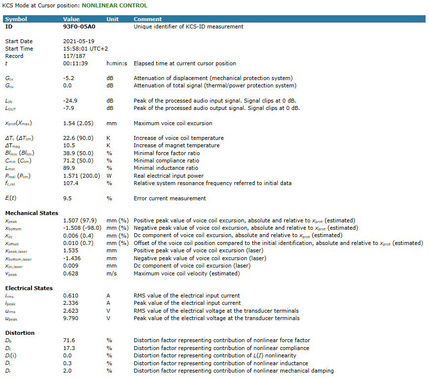
The State window gives information about the current controller states, information about the measurement, modeled and measured transducer states and electrical parameters at the current position of the time cursor.
If KCS is running, also the control mode can be changed using buttons at the top of this window.
Note
It is recommended to always have this window visible as important errors and warnings are displayed here.
Setup#
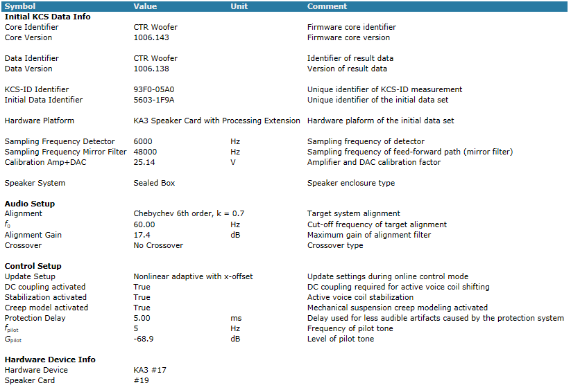
You find additional information about KCS setup, hardware platform and initial KCS data here.
Alignment#
This section describes the filter types available for the high pass filter alignment. See Tutorial 4 – Alignment and Equalization for practical tips how to use this feature and to incorporate it in the system tuning process.
Second Order Alignment#
2nd order alignments are only available for 2nd order systems (sealed boxes or transducer in free air). The alignment replaces the given system’s resonance frequency and Q-factor by a desired cut-off frequency and Q-factor.
The target transfer function is
with Q denoting the target quality factor and \(\omega_c\) the desired cut-off frequency in radians.
Butterworth and Chebychev Alignments#
These alignment types are available as 4th and 6th order filter types. The target transfer function for a Chebychev alignment is
with k denoting the Chebychev parameter, N the order of the filter and \(\omega_\mathrm{c}\) the desired cut-off frequency in radians. The Butterworth response is equal to the Chebychev response with k=1. The poles are a spread in equal distance over a circle in the complex plane.
Bessel Alignments#
Bessel alignment types are available as 4th and 6th order filter types. The target transfer function of order N is
Contrary to the other filter types, the cut-off frequency \(\omega_\mathrm{c}\) does not describe the 3dB decay from the pass band gain but a correction factor \(c_{N}\) is introduced to reach this behavior. The correction factors for 4th and 6th order filters are \(c_{4} = \ 0.47306,\ c_{6} = \ 0.36991\).
Comparison of different Filter Types#
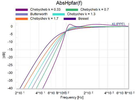
The chart above shows the magnitude of all available 4th order alignments. While all transfer functions result in a decay of 20dB per octave, the filter type determines how fast this slope is reached below the cut-off frequency. A Chebychev alignment with k=0.33 will reach -40 dB attenuation around an octave higher than its counterpart with k=0.7. This causes a higher pass-band ripple and faster changing phase shift resulting in a higher group delay, though.
The 6th order alignments show similar behavior reaching slopes of 40 dB/octave, but exhibit higher phase shifts (360°) and group delays.
Hardware Connection#
Klippel Analyzer 3#
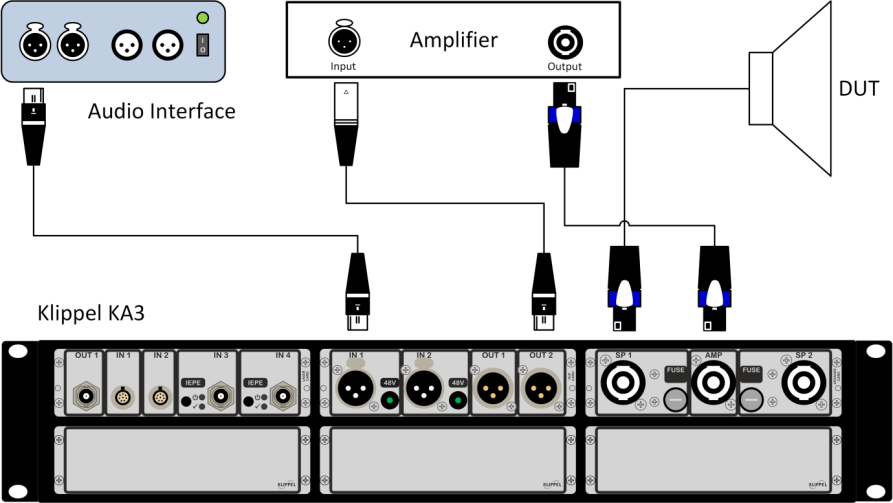
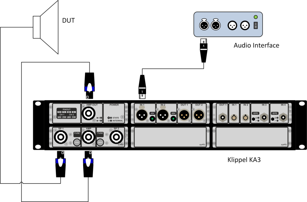
The minimal hardware setups on the KLIPPEL KA3 comprising one SPEAKER CARD, one LASER CARD, one XLR CARD and an optional AMP CARD is illustrated in the figures below. For more Information about the hardware, please see the Hardware Manual [Hardware].
Note
Laser and microphone sensors are not necessarily required for operating the KCS. However, these sensors are recommended for evaluating its performance, such as nonlinear distortion reduction and mechanical protection system. In addition they are necessary for performing measurements on the transducer, such as irregular distortion (Rub&Buzz) measurements. The laser is particularly useful for identifying the force factor Bl(x=0) prior to operating KCS.
Nuvoton Audio Development Platform#
Perform the following steps and connect the hardware according to the following pictures.
Connect the speaker(s). Make sure the polarity is correct.
Connect the power supply. If you change or reconnect the speaker later, unplug the power supply before to avoid hardware failure due to accidental shorting of pins.
Connect USB to the PC
See Nuvoton’s NAD Quick Start Guide for more information.
NAU83G10#
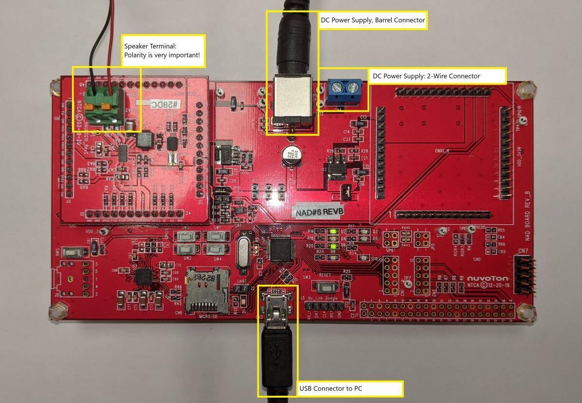
Warning
Do not use a power supply with a voltage higher than 5.5V. This would damage the chip.
NAU83G20#
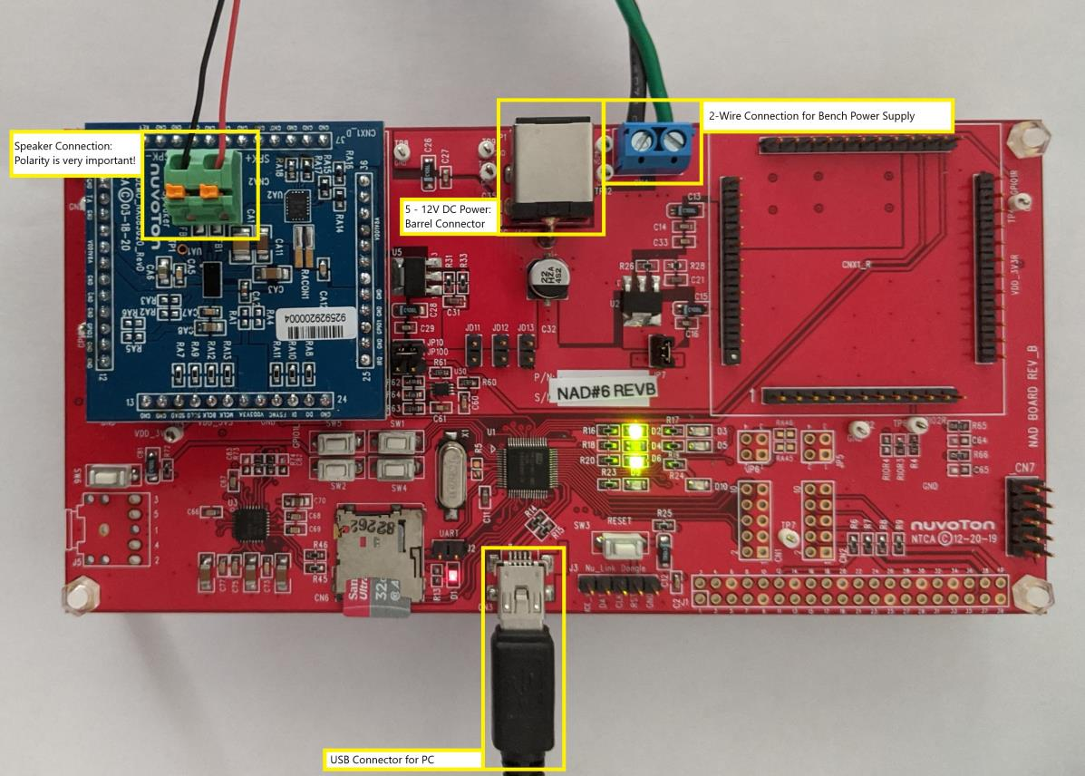
NAU83G60#
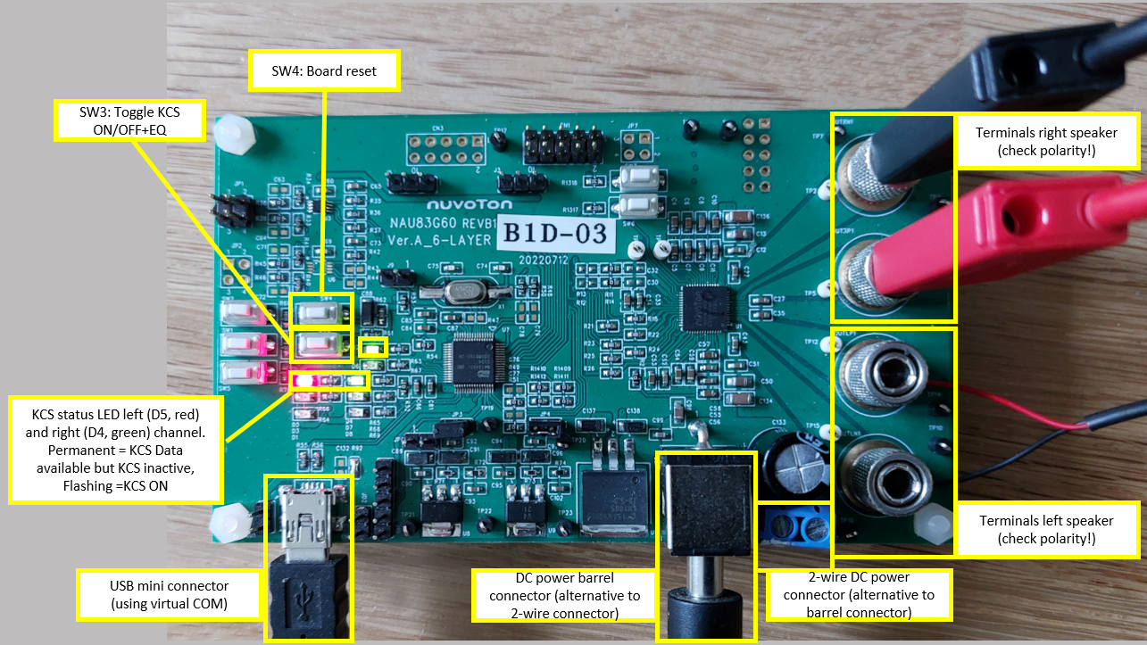
Note
Make sure to use an appropriate power supply. NAU83G60 has no boost converter, so the power supply output voltage restricts the available rail voltage of the amplifier. Please refer to the NAU83G60 Quickstart Guide provided by Nuvoton for details and spec.
Things you should never do#
Although we tried to organize the user interface to avoid misuse, you should be aware of the following:
Never mismatch initial parameters and loudspeakers#
Initial parameters identified on a particular loudspeaker model can usually not be used to control a different loudspeaker model unless the linear and nonlinear parameters of both loudspeakers are very similar. The initial data also comprises the acoustical load (enclosure). The same enclosure or an enclosure of very similar properties (same volume, same port geometry if a port is used) has to be used in KCS-ID and KCS on-line operation.
Note
Every initial data set has two unique 8-character identifiers KCS-ID Identifier (assigned by the KCS-ID operation) and Initial Data Identifier (assigned by the KCS-Server) which are displayed in the window Setup.
Never change the enclosure#
KCS can be used with loudspeakers operated in free air as well as with vented and sealed enclosures. This information is entered before starting the Initial Identification (KCS-ID). Changing the type of the enclosure type or size requires a new KCS-ID Parameter Identification to create a new set of initial parameters.
Never change the polarity#
Usually, loudspeaker parameters have an asymmetric characteristic making the polarity of the connections at the loudspeaker terminals critical for the compensation of nonlinear distortion. Never change the polarity after the initial identification (KCS-ID) as this will lead to additional nonlinear distortion and a wrong identification of the voice coil rest position.
Never change the routing in dB-Lab’s KA3 Signal Configuration while KCS is in operation#
Please observe that KCS even might be in operation in standalone-mode, even though KCS Monitor is currently not running. Changing the signal configuration anyway might bypass KCS processing in the signal chain, so that the connected speaker is not protected by KCS. This might lead to overload. Overloading of the device might harm both the speaker and your hearing.
Troubleshooting#
Message Boxes#
Connect to device failed#
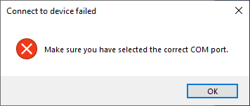
Make sure the correct KCS device is connected to the PC. Select another COM port and connect again.
Measurement is running on the device#
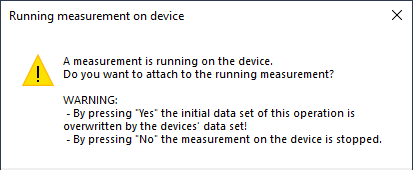
This message appears if the KCS Monitor operation is started and a KCS on-line session is already
running on the hardware device. Press Yes if you would like to overwrite the initial data stored
on the device and start a KCS session. Press No to terminate the control session which is running
on the device. In this case the KCS Monitor operation stays untouched. If the operation is started
, the initial data stored in this operation is written to the device and the KCS on-line
processing is started.
Uploading Data from Device#
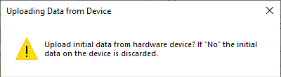
If the KCS Monitor operation does not hold any initial data but the connected device does, you have the possibility to upload initial data from the device to the KCS Monitor operation or to delete the initial data on the device.
Selected warning messages#
The warning messages are shown in the KCS Monitor’s State window.
Output clipping#
Cause: The output of the KCS on-line processing exceeds approx. -0.5dB of the expected maximum output voltage.
Remedy: Decrease audio level, decrease the Excursion Limit or activate the limiter in the Properties.
Warning
If this warning is displayed, audible artifacts due to clipping can occur.
Even if this warning is not displayed, clipping can occur because the exact maximum ratings of the connected hardware are not always known (e.g. maximum rail voltage depends on connected PSU).
External input signal is limiting. Reduce audio input level to avoid clipping.#
Cause: The input of the KCS on-line processing (before or after the KCS audio gain stage, which value is defined on the KCS Monitor’s property page) exceeds approx. -0.5 dBFs.
Remedy: Check the IN level in the window State. If it is close to 0dB, reduce the input level. You might increase the KCS audio gain in the KCS Monitor property page (Audio Gain slider). Make also sure that IN level plus audio gain level is not exceeding 0dB.
Warning
If this warning is displayed, audible artifacts due to clipping can occur.
Temperature too high#
Cause: The measured increase of the voice coil temperature exceeds the limit defined in the KCS Monitor’s property page.
Remedy: Make sure that a speaker is connected and the correct initial data for the particular DUT is loaded.
Insufficient Bl(x) decay. No x-offset updating possible!#
Cause: For identifying the voice coil rest position, KCS evaluates the nonlinear distortion found in the measured current signal caused by the nonlinear Bl(x) speaker characteristic. If the Bl(x) decay is too small, voice coil position identification will not work:
Remedy: Use a driver with more nonlinear Bl(x) curve or, if possible, relax the limits in the KCS-ID (e.g. increase the target excursion).
Note
KCS will work anyway, but higher safety margins for the maximum allowed excursion are required because the exact voice coil position is not known. Active voice coil stabilization will not work if this warning is displayed.
Other Issues#
Bad Audio Quality – Impulsive distortion#
See section How to Treat Rub & Buzz Issues in KCS Evaluation Tutorials.
Lack of Bass#
Set an alignment with an appropriate frequency fc.
Mechanical Protection System is active (see Tutorial 5 – Protection and Limiter). In this case reduce the audio gain.
Contact KLIPPEL support if you cannot solve any KCS issues or have other questions.
