
PNI – Production Noise Immunity#
PNI - Tutorial#
Overview#
Production Noise Immunity Module (PNI) is an add-on option to the standard sound pressure (SPL) task.
An intelligent auto repeat algorithm is used to avoid corrupted verdicts due to ambient noise. Valid signal parts can be separated from corrupted parts and be stored and merged to a complete measurement signal. Even in permanently disturbed environments such as a typical production floor, acoustical systems can be tested reliably. No good unit will be rejected by the test due to noise corruption anymore.
Thus, a higher robustness for end-of-line testing in a noisy production environment is provided.
Note
Note, that a special license is required.
The Ambient Noise signal is recorded using a second microphone separated from the actual measurement microphone (usually in near field) by space or test enclosure.
Note
Ambient Noise Detection is part of the Standard QC function and does not require the Noise Immunity Module. It is restricted to the simple detection of ambient noise corruption. A Noise warning is issued in this case but the test won’t be repeated.
Which Results are Protected by PNI?#
The PNI protects the following measurement results:
Frequency Response
Level (average level)
Polarity
THD , 2nd – 4th harmonic distortion
Rub&Buzz
3DL – Spectrogram (requires 3DL – Spectrogram 3D Limits add-on)
Frequency Response, Harmonics, Rub&Buzz and 3DL Spectrogram are checked directly exploiting the ambient noise microphone signal.
Level and Polarity are checked based on the frequency response data. For those measures the frequencies of frequency response, which are required for calculation, are checked for noise corruption. If such frequencies are corrupted and the limit check failed, they are marked as Warning with ‘- noise’ added.
How Does It Work?#
In the graphics below a typical sequence is shown to illustrate the principle of PNI.
Let’s assume that the measurement is disturbed by impulsive noise incidents happening randomly (e.g. dropped tools, machinery operated on production floor). In each run the algorithm checks for ambient noise disturbances. Undisturbed parts of the measurement are stored, while disturbed frequency ranges are marked red. In the subsequent automatic test runs the corruption is detected in other parts of the sweep signal response.
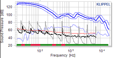
Using a merging algorithm, the test is repeated until all frequencies are validly tested without noise corruption (marked green). In the example the red parts in second and third row indicate, that those frequencies in all previous runs were noise corrupted due to overlapping of corrupted frequency ranges in the runs.
Note
Note, that the actual disturbed ranges are not shown, only the accumulated disturbed ranges. Thus, even the last run (last row) may be noise corrupted at frequencies, where previous runs were noise free.
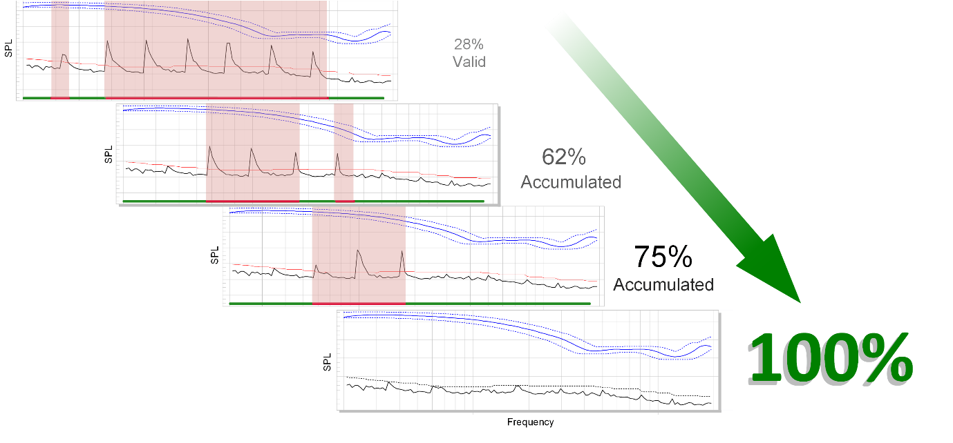
In case a result parameter fails at undisturbed frequencies, the repetition stops and the failed verdict are shown (not shown in the example).
Merging is applied only, when using the Replace Corrupted frequencies mode. In Replace All frequencies, the test is repeated until one complete undisturbed run was found (no accumulation is applied).
Note
When testing 3DL Spectrogram, only full test repetition is available. Merging is currently not supported.
Getting Started#
Installation#
The PNI option is automatically made available in case a valid PNI license is available. Simply double click the distributed license file or, if PNI was ordered at the purchase of the QC system, it will be automatically installed using your installation CD.
You may check the installed license using .
Setting Up the Hardware#
The Production Noise Immunity Module requires the standard QC system setup according to QC User Manual / Getting started / Hardware Installation / Connecting the system.
Note
Note that a dedicated microphone is required to measure ambient noise with sufficient distance to the DUT, outside of the test chamber (if available).
For microphone selection, calibration and setup, please refer to section QC User Manual / Optimizing performance / SPL Tests / Microphone Selection.
Connection of the Ambient Noise Microphone#
By default, the noise microphone shall be connected to secondary input according the articular front-end used (e.g. MIC2 input input). However, the noise microphone must be routed accordingly in the test sequence.
The input channel can be assigned globally for the full task sequence in Control: Start task
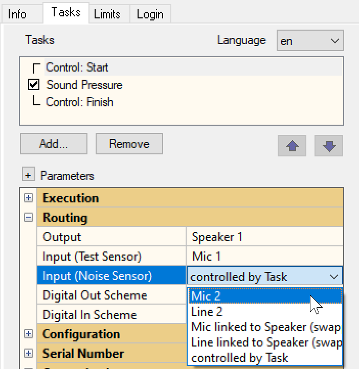
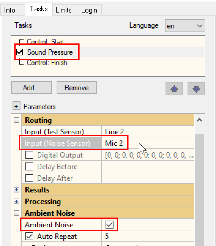
or individually in each task when setting global routing to controlled by Task. Consequently, in the SPL task a section Routing is shown. When Ambient Noise is activated, the input of the noise microphone can be selected.
Measurement Conditions#
For Production Noise Immunity the measurement conditions are extremely important.
Noise immunity technology can only be applied, if the noise microphone measures considerably less (12 dB) SPL output from the DUT than the test microphone. The easiest way to ensure this is using a test enclosure.
Using a Test Box#
The optimal solution to handle ambient noise is a well-designed test box.
See also
Please refer to application note AN45 Test Enclosures for QC.
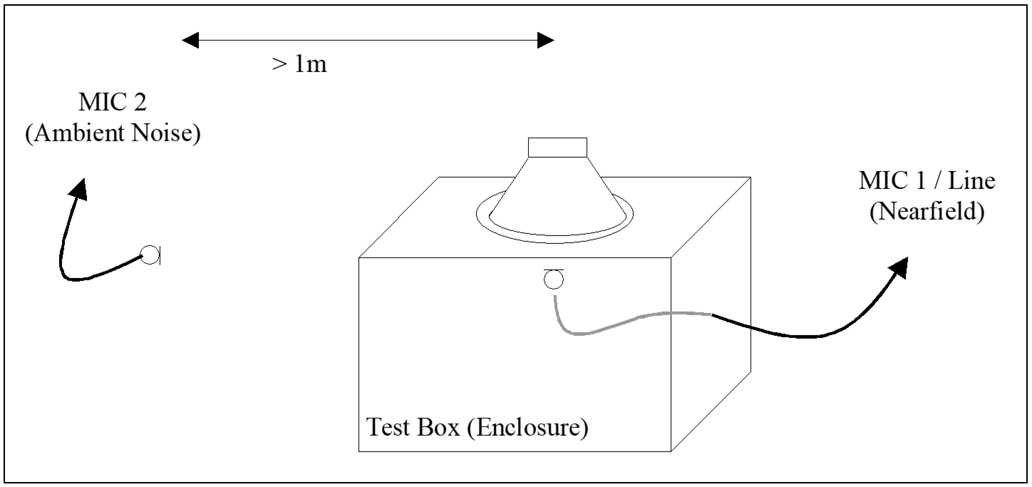
The PNI algorithm relies on an accurate measurement of the test box attenuation. Please refer to the QC-User manual section QC User Manual / Optimizing performance / SPL Tests / How to cope with Ambient Noise?
In case, the attenuation of lower frequencies is not sufficient, consider using the setup parameter Rub&Buzz Minimal Frequency.
Testing in Free Air#
If a test box cannot be applied, testing in free air is also possible. However, the following restrictions apply:
The test microphone should be as close as possible to the DUT
The noise microphone should be at least 1 m … 2 m (or more) away, preferably at 90 ° off the main radiation axis.
The noise microphone may be above the DUT at the above-stated distance
The room (volume) within the radius defined by the distance of the noise microphone from the DUT must be free of any parasitic noise source.
An SPL difference (ratio) of at least 12 dB between test and noise microphone radiated by the DUT must be ensured. This ratio is automatically calculated during the limit calculation process and displayed in Auxiliary window. If the ratio is less than 12 dB, a warning is displayed and any measurements using this setup are blocked by an error message. See section Error: Noise Microphone is too close to DUT.
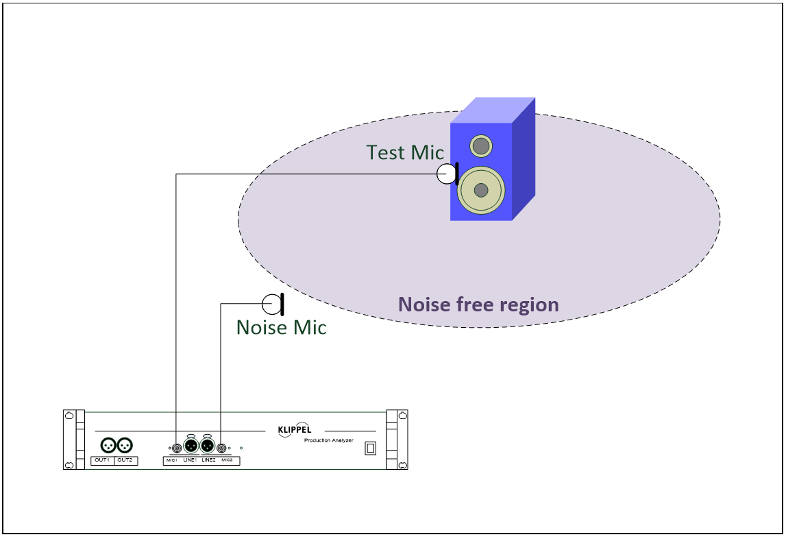
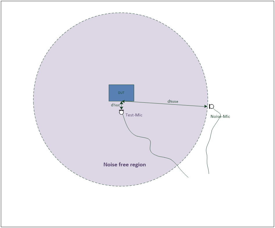
Further recommendations:
Maximize ratio \(d_{\text{Noise}} / d_{\text{Test}}\)
If the required ratio of 12 dB cannot be realized due to room modes / reflection or other acoustical causes, consider using shielding walls or semi-open enclosure. See chapter QC User Manual / Optimizing performance / SPL Tests / How to cope with Ambient Noise? for details.
Performing a First Measurement#
Setting Up the SPL Task#
Production Noise Immunity is an optional feature of the standard SPL task. An existing SPL task in your sequence can be used or a new SPL task may be inserted. See the QC User Manual User Modes / Engineer / Property Page Tasks / Adding / Removing a task for details. All steps in section Getting Started must be completed before using.
Activating Noise Immunity#
All PNI related settings are grouped in the section Ambient Noise. Enable Ambient Noise and Auto Repeat as well. Enter a number of maximal repetitions and select the Replace mode. Also, select the Microphone setup according to your test scenario.
For all settings, see the PNI - Reference section for details.
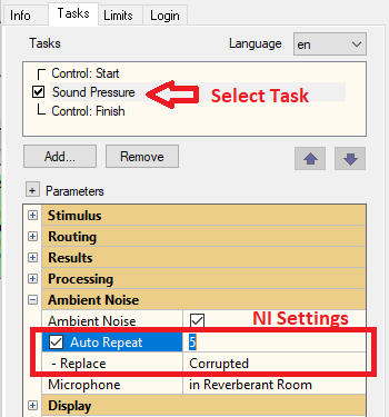
Note
The parameters marked red are exclusively used by the PNI. The other parameters in the Ambient Noise section are also used for Ambient Noise Detection, which is part of the Standard SPL Task. If an existing test from older QC software versions is used, the PNI settings may be not visible. In this case, old Reference DUTs must be discarded and replaced. Simply deactivate Ambient Noise checkbox and press OK. Re-enable it again and confirm with OK. Now the settings are visible as shown above.
Running a Test#
Simply start the test as usual. To verify the proper operation of the PNI, test limits are mandatory. Measure at least one Reference DUT in Limit Calculation Mode and calculate limits.
Limits#
There are not dedicated limit parameters for Production Noise Immunity. See section Limits for Details.
Note
Note, that the following PNI settings can be altered without discarding the reference DUT’s:
Auto Repeat On/Off
Number of Auto Repeat loops
Replacement mode (All, Corrupted, Selected modes)
Select Measures (in Selected mode only)
Altering the activation switch Ambient Noise as well as the Microphone position requires the re-measurement of reference DUT’s if Reference DUT integrity option is enabled.
Evaluate Production Noise Immunity#
Consider the following steps to get familiar with PNI. Also check the section Viewing and Analyzing Results below to learn about the display options and results.
Ambient Noise must be kept enabled. The microphone position cannot be changed without discarding the Reference DUT’s. The noise prediction depends strongly on this setting. Try different setups to see the effect on the noise prediction and test limits.
PNI specific settings (Auto Repeat and Replacement Mode) can be changed without discarding Reference DUT’s. Try both replacement modes and high / low number of allowed repetitions.
Make limits in a relatively quiet, but realistic environment (similar to final operation). You may deselect or delete Reference DUT’s, which are noise corrupted. It is good practice to measure 5 to 10 reference DUT’s to achieve more stable limits by averaging different objects.
Note
Rub&Buzz limits are based on the overall peak values of the reference DUT’s, not on the average.
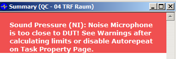
Make sure, that the noise microphone is not too close to the DUT. After calculating the limits, there should be NO warning such as Noise Microphone is too close to DUT! If the warning appears, check the section Error: Noise Microphone is too close to DUT.
If you are using any box enclosure you may use the predefined box attenuation applied when selecting Microphone – in Box Enclosure (15 dB for all frequencies). To optimize PNI you may also measure and fill in the actual attenuation curve of your test setup. See the QC User Manual in section Optimizing Performance / SPL Tests / How to cope with Ambient Noise for details.
The most critical case for evaluating Noise Immunity is free air condition. In reverberant rooms or in situations with strong reflections, make sure the microphone setting is set to Reverberant Room. However, try to avoid this setup, if possible. It may reduce the sensitivity of your measurement (limits) significantly. See section Tips on Free Air / Reverberant Rooms for Details.
If you encounter warnings, see section Error Messages and Warnings.
Avoid coupling of structure-borne noise to the DUT. If possible, decouple the whole test fixture from the surrounding.
If the major source of disturbance is structure-borne noise, an acceleration sensor may be used instead of the noise microphone. Multiple positions shall be checked for mounting the sensor for best performance.
Try different sources of ambient noise such as loud talk, clapping hands, dropping and hitting parts. Make sure, the noise source is far apart from the noise microphone as well from the measurement microphone.
Viewing and Analyzing Results#
Show Noise Curves#
In the Display section enable the Show Noise checkbox. As all display settings, this does not affect Reference DUT’s. You may switch this setting off by default and in case of diagnostics enable it before or after a measurement.
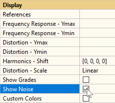
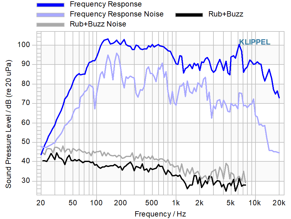
All noise curves have the same basic color as the corresponding measure but are dimmed in color intensity.
Final Results of Production Noise Immunity#
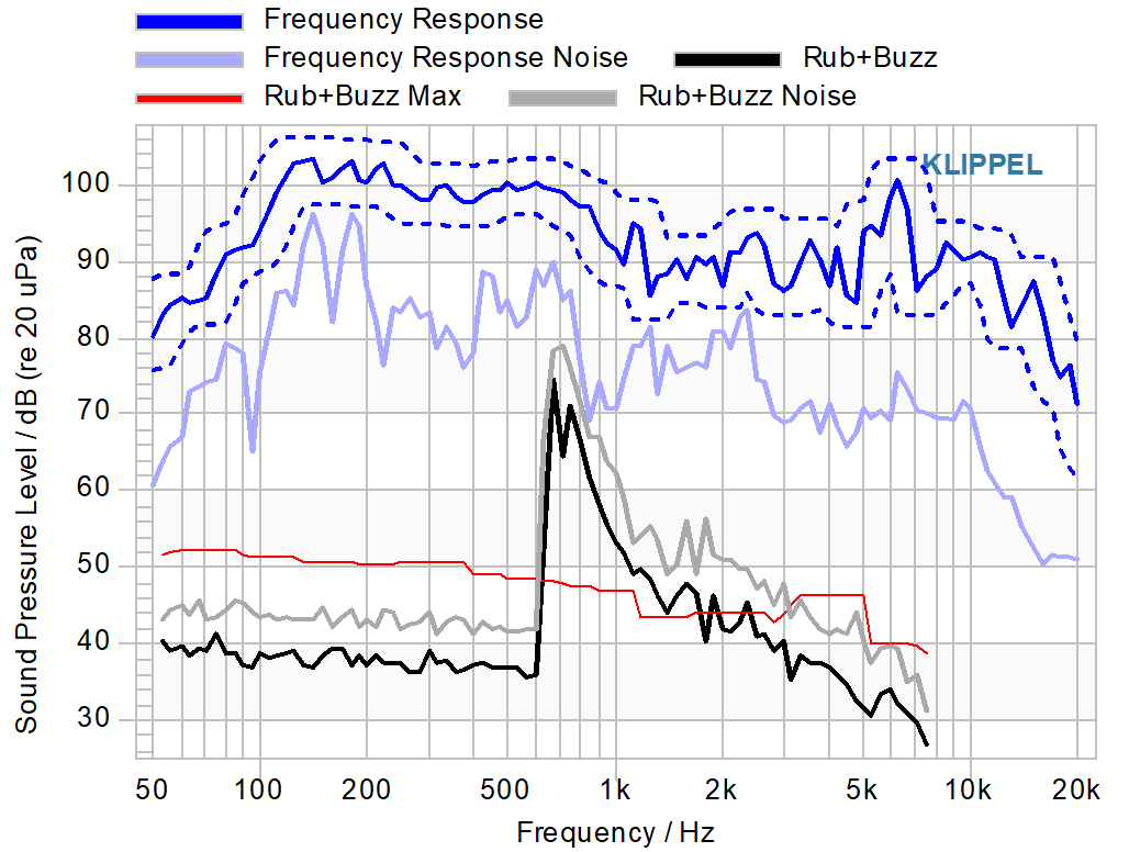
Using the Rub&Buzz as an example of typical combinations of noise and measures are listed.
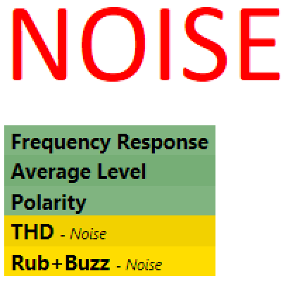
If the maximal set number of repetitions is reached, an overall verdict “NOISE” will be generated which is rated as a failed measurement. A comment is shown on the summary page, that the maximum number of repetitions has been reached.
Noise Corrupted Test#
noise and test channels exceed limit in the same frequency range
Max. number of runs is exhausted
The dominant cause of limit violation is ambient noise
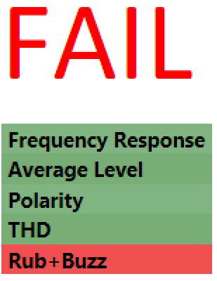
Rub&Buzz Defect#
Test channel exceeds limit
Noise channel is below limit or much lower than measure
No more repeats are made
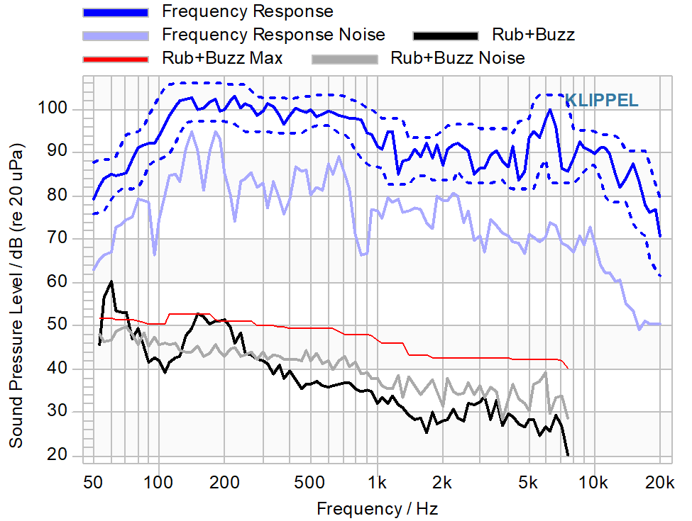
Dominant Defect#
test and noise channel violate limit
the sound of a strong defect may also violate the noise limit
special processing detects this case by predicting the noise caused by defect
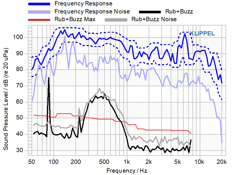
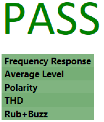
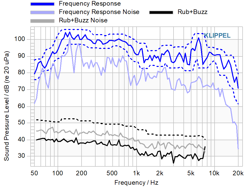
Neither Noise nor Defect#
Test and noise channel are below limit.
Interim Results#
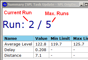
During the auto repeat of tests, the current status of the test is displayed. Each single measurement is designated as Run.
In Replacement Mode = All, the current run and the maximal number of runs (defined by the Autorepeat field on Property Page TASKS) are shown.
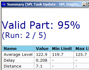
In Replacement Mode = Corrupted, the percentage of undisturbed frequency regions (100 % correlates to complete undisturbed test) and number of run is shown:
Furthermore in Frequency Response chart the regions of noise-disturbed frequencies are marked with a red bar below the curves, while the accumulated good regions are marked green.
Note
To Module Owner: New Screenshot, bad axis labels
Optimizing Production Noise Immunity#
Tips on Free Air / Reverberant Rooms#
In free air condition and especially in reverberant rooms please check the following points:
Set the Microphone Position to Reverberant Room, if the noise detection is not reliable.
To increase robustness of high-level signals, use the Replace modes All (Selected) or Corrupted (Selected). In these modes you may individually switch on/off measures, which are noise monitored.
Repeating very short tests (200 ms sweep): The decay of the room modes may take longer than the repetition of the test. In this case, room modes may appear as Rub&Buzz defect at very low frequencies. This happens at each run, so the algorithm will never find valid data at those frequencies.
Note
Hint: Allow room modes to decay, use a delay after each test. See section QC User Manual / Test Configuration / Routing for details.
Check carefully the test sequence to avoid the same effect between consecutive tasks.
Make sure that the test and the ambient noise microphone is at least 1 m apart from the closest wall. Potential standing waves / room modes have pressure maxima on the walls and will interfere with the Noise Immunity Module.
Check carefully to use any means of test enclosure. This may be a test cabin with absorptive walls or a semi open space.
Make sure, that the noise floor of the Ambient Noise microphone is lower (at least equal) than the measurement microphone.
Locate the measurement microphone on axis, while the noise microphone off axis related to the DUT.
In case of problems, please send a test database to support for further comments and optimizations.
Exploiting PNI for Fixed Test Regime#
A test regime with fixed timing is assumed as testing every \(n\) seconds. This setup is used in automated environments. Depending on the available time the number of repeats may be defined.
However, also if no repetition can be allowed, the Production Noise Immunity Module provides the benefit of detailed separation of Noise and Fail verdict.
It is possible to set the Auto Repeat number to 0 using the Replace=corrupted mode. Assume the case as depicted below, that below 100 Hz the DUT has a defect (noise below limit) while at around 500 and 1000 Hz the test is corrupted by noise (noise and measure above limit).
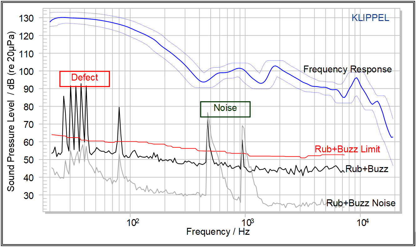
Without Noise Immunity Option the verdict would be NOISE, since noise and measure exceed the limit. There is no separated check in the standard QC Version, where and in which combination the limits are exceeded.
Using Noise Immunity the verdict is FAIL, since below 100 Hz there is no noise corruption but the measure exceeds the limit. This separation of the frequency band is provided in the Replace=corrupted mode only.
More Information about Ambient Noise#
Please find more information about Ambient Noise here:
General information and setup of Ambient Noise Detection in QC Standard version (without Noise Immunity): QC User Manual / Test Configuration / Tasks / SPL / Ambient Noise
Optimizing Ambient Noise Detection in QC Standard version (without Noise Immunity): QC User Manual / Optimizing performance / SPL Tests
Background information about Ambient Noise Prediction (Theory, Calculation): QC User Manual / Measurement Technique / Prediction of Noise
Trouble Shooting Production Noise Immunity#
In case of problems with noise monitoring / noise immunity check the following points:
If you miss noise events and the DUT failed due to ambient noise, check first the correct calibration of the microphones and the connection of both microphones.
For diagnostics, enable the Show Noise check box in section Display on Property Page TASKS.
Always compare the actual measured curve with the according noise curve. The shown noise curve is predicted (transformed) to the location of the measurement microphone. This allows the use of one limit only for both, the noise and the measure curve. Check the violation of this unified limit.
If you encounter too many noise verdicts, it might be that you measured the reference DUT’s in a silent environment and that the ambient noise level got higher during real production. In this case, it is recommended to record about 10 Reference DUT in typical noise conditions. You may use just one Golden Sample or more reference samples, if you have. This is to statistically find the level of noise. Check the reference DUT’s for extremely high noise peaks; do not use those DUT’s for Limit Calculation.
If a strong defect causes a Noise verdict, make sure, that the setup microphone position is correct. If you are using a test chamber or test box, you should consider measuring the actual attenuation than using the simplified default box type. Refer to the QC User Manual for instructions on measuring the attenuation of a test box. On the Summary page a link Show Details of Noise Immunity may be available, which offers detailed information for diagnostics in this case. Please send the database with a description of the test environment and used microphones / positions to support.
Check the error and warning description at the end of this Manual for more information on specific problems.
PNI - Reference#
Results#
The Noise Immunity Module protects all activated measures of the SPL task. Those measures are described in the QC User Manual in section Tests Configuration/Measures and Limits. The primary result is the robustness against Ambient Noise and minimization of measurement time.
Measurement Setup#
There are two dedicated parameters for Noise Immunity on the Property Page TASKS. For all other parameter, see the QC User Manual.
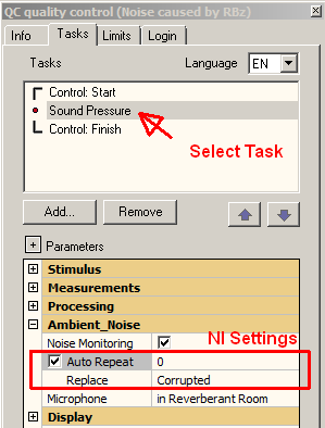
Auto Repeat#
To activate the Noise Immunity Module enable Auto Repeat in section Ambient Noise on the TASK Property Page. The maximal number of measurement repetitions in case of noise corruption can be entered.
Please check the section Exploiting PNI for Fixed Test Regime for more details on setting Auto Repeat to zero.
If left empty, the max number of repeats is set to zero.
Replace#
Activating the Auto Repeat check box will enable the select list Replace. This parameter controls the working mode of the Noise Immunity algorithm.
- All
The complete measurement will be replaced in case of corruption. In this mode the test will be repeated until one completely undisturbed measurement was found. This setting needs more runs to achieve an undisturbed measurement but is by design more robust. In case of permanent disturbances no undisturbed measurement can be achieved.
- Corrupted
Corrupted will activate merging. Thus undisturbed signal parts are accumulated. See section PNI - Tutorial / How does it work? for details. This setting minimizes the number of repetitions. The noise attenuation of the enclosure and microphone position setup must be accurate in this case.
- All (Selected), Corrupted (Selected)
In addition to the basic replace modes the keyword Selection indicates, that the measures that are monitored by Noise Immunity may be selected individually. See section below.
Select Measures#
If the replace modes with keyword (Selection) are selected, for all measures noise monitoring can be switched on/off individually. This can be useful, if high-level tests are performed (no need to monitor Frequency Response and derived measures as level and polarity) or if noise disturbance can be reliably detected on selected measures only (e.g. Rub&Buzz).
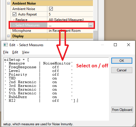
This is an advanced setting and may impair the noise detection. Make sure that you understand the consequences of disabling noise monitoring.
PNI Setup#
The Select Measures parameter is a string matrix with the following format:
Measure       | NoiseMonitor
FreqResponse  | off
Level         | off
Polarity      | off
THD           | on
2nd Harmonic  | on
3rd Harmonic  | on
4th Harmonic  | on
5th Harmonic  | on
Rub&Buzz      | on
On the left side all measures (also inactive one) are listed. Just modify the on/off switch to de-/activate the noise monitoring for the stated measures.
In case the input parameter check complains about wrong syntax, you may always restore the default setup (as shown above) by the following steps:
Open the Select Measures Parameter dialog
Clear all text in the box
Logout, ignore further error messages about wrong syntax
Login again. The default state is restored for this parameter.
Noise Monitoring | Microphone Position | Show Noise#
These settings are also used for Ambient Noise Detection, which is part of the Standard SPL Task. Therefore those parameters are described in the QC User Manual.
Limits#
There is one unified limit for each actual measure and the corresponding noise. This can be achieved by preprocessing the noise measurement.
There is no dedicated limit parameter for noise limits. All limits for noise detection and processing are calculated based
on the limit settings for the activated measures and
on the microphone position and potential box shielding
See the QC User Manual section Appendix / Measurement Technique / Ambient Noise Detection and the specification S21 Noise Immunity for details.
Error Messages and Warnings#
Warnings#
Warning
Measurement may be corrupted by noise.
This Warning is generated in Limit Mode only. A simple estimation is implemented to detect if noise corruption may exist although there are no limits yet:
If the Rub&Buzz result from the noise microphone is higher than from the test microphone, this warning is generated.
If this warning occurs when testing in a test enclosure, although there is no excessive noise, please check the setting of Microphone Position on Property Page TASKS.
In this case, check the noise level during the measurement. Enable the Show Noise option on Property Page TASKS in section Display. Disable or delete all Reference DUT’s with excessive Noise characteristics.
Note
Note that even in this case the test results are reliable. However, the limits for noise disturbed results may be affected. A detailed message is generated when actually calculating the limit (explicitly calculate limits or leaving limit mode).
Warning
Attenuation should be positive.
By default, the attenuation of the test enclosure should be positive. This is the damping of sound from Ambient Noise into the test chamber.
However, if other sensors such as Acceleration Sensors are used, it might be required to specify the transfer function using negative attenuation. In this case the warning may be ignored.
Warning
Noise Signal is higher than Near-Field Signal
The Production Noise Immunity Module guarantees uncorrupted measurements. To ensure this feature, the predicted noise of a good (not disturbed) test of the reference units must be lower than the measure to be supervised for all frequencies.
Especially if the noise attenuation is low (free air condition, bad damping of test box), this is not always the case. To ensure noise immune testing, the limit of the susceptible measure is relaxed and the sensitivity of the test is therefore decreased.
If the system detects this case, a warning is issued when calculating limits in the Summary chart. Click on the link Show Details to see, which measure is affected most and at which frequency the problem was detected.
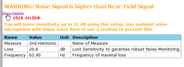
In this case, it is recommended to
Use a test box if possible.
Use a more sensitive microphone for the ambient noise. The level of the ambient noise is usually much lower and hence more sensitive microphones with lower noise floor can be used.
Relax the limits of the susceptible measure to have this loss under control.
Identify and remove permanent noise sources in the vicinity.
Note
This Warning also happens with Metaharing Prefix during regular measurements. In this case the active compensation of the Meta Hearing Technology is achieved but cannot be used, since the noise level during Limit Mode was too high. The same recommendations listed above apply.
Errors#
Error: Noise Microphone is too close to DUT#
Especially in free air conditions the noise microphone must be positioned carefully. Usually the measurement microphone is to be located in the near field and on axis of the driver / system. The noise microphone should be located off axis and at much higher distance from the DUT. For more information on microphone position refer to the QC Quality Control user manual section Test Configuration / Tasks / SPL / Ambient Noise / Setup / Microphone Position.
Note
If testing a car body or similar setup, where the assumption of locating the test microphone in the near field of the DUT is not true, use the special mode microphone position: in car.
For a proper setup, the noise microphone level must be lower than test microphone level by a defined value:
Microphone position |
\(L_{\text{shift}}\) |
|---|---|
Free Air, Reverberant Room, Box Enclosure |
12 dB |
Car |
0 dB |
If this condition is violated, a warning is presented in the Summary chart (here for \(L_{\text{Shift}} =\) 12 dB):
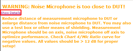
This Warning is shown after calculating limits only. Please check in this cases Auxiliary Chart, were the ratio of recorded signals
is shown.
Note
No processing but 3rd octave smoothing is applied. For checking the microphones (sensitivity, relative frequency response) both microphones can be put together at one location, a 0 dB flat line should result.
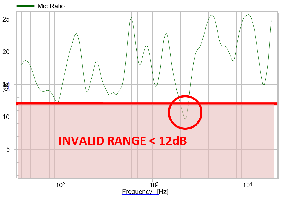
Performing a measurement against limits is blocked in this case:
Recommendations in this case:
Locate measurement microphone on axis closer to DUT
Locate noise microphone in more remote position, avoid strong reflections and structure born noise coupling
Use test box or any means of shielding (semi open enclosures), if possible.
Use more microphones and microphone multiplexer for multi-channel systems
Avoid corners and edges for noise microphone (room modes).
