
ALD – Air Leak Detection#
ALD - Tutorial#
Overview#
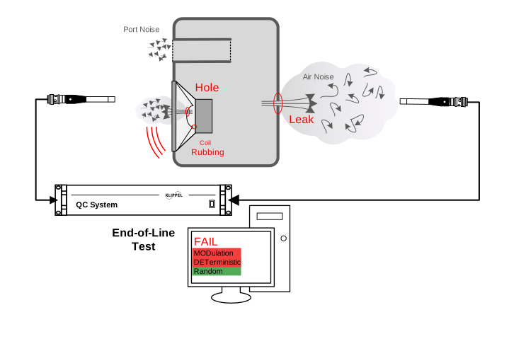
The Air Leak Detection (ALD) is an add-on to the KLIPPEL Analyzer System for the QC – Quality Control end-of-line testing framework. It is dedicated to detecting air leaks in enclosures, dust caps, and other parts of loudspeaker systems.
The analysis is based on a demodulation technique and a specific harmonic distortion analysis providing unique symptoms of turbulent air noise and leak-induced distortion to distinguish this defect from rub and buzz, loose particles and other failures. This ensures high detection sensitivity even in some distance from the source.
This module provides two options to detect air leak defects:
- The separate ALD task
Using a fixed-frequency tone, air leakage defects are detected with very high sensitivity for extremely small leaks. In addition, driver defects or loose particles are identified and classified.
- ALD integration into SPL task
A user definable part of the log sweep stimulus used in the Sound Pressure task is analyzed providing the same measures as in the separate ALD task.
Both implementations support multiplexed microphone arrays located around large measurement objects (large enclosures). The powerful tool combines easy handling with high-speed measurement and robustness against ambient noise.
The module can be applied to complete loudspeaker systems and all kinds of transducers such as woofers, tweeters, headphones, micro-speakers and compression drivers.
When Using Separate ALD Task#
Using the separate ALD task, leak symptoms are assessed at a constant frequency. Therefore, any change of leakage symptoms versus frequency is not impairing the sensitivity. This option provides the highest sensitivity at the expense of measurement time.
In addition to the measures focusing on air leak, it also provides a very sensitive measurement of deterministic Rub&Buzz detection. This is possible by averaging and therefore noise suppression using a single tone excitation. Depending on measurement time it can be much more sensitive than the sweep-based solution in the SPL task. However, no wide-band analysis is possible as it is only a focusing at a single stimulus frequency. Some Rub&Buzz defects only occur at specific excitation frequencies.
For applications with larger size DUTs such as speaker systems or particular subwoofer products, multiple microphones might be required to reliably detect all possible leak defect sources (e.g. terminals, gaskets, handles, welded joints…). See also typical applications on the KLIPPEL website . For those applications, the separate ALD task provides the optimal solution for all test locations, where no frequency response is to be measured and radiated. Usually only one microphone location is sufficient checking the frequency response of the system, others are used to check for air leakage symptoms and other defects only.
When Using ALD Integration in SPL Task#
Leak detection integrated in Sound Pressure sweep provides the fastest measurement method if other results from SPL task are required. This method inherently analyzes a certain part of the sweep response for air leakage symptoms. Thus, it is averaging the symptoms in a user-defined frequency band. This can be more versatile than a single tone but is also vulnerable to varying symptoms and hence a loss of sensitivity.
Sufficient response sound pressure level (especially at low frequencies) is required within the analyzed band for this integrated solution. Thus, it is optimal for leak detection within or close to radiating cones or panels whereas the separate ALD task shall be used for pure defect detection with poor radiation of fundamental frequency within the test bandwidth.
Air Leak Detection Task#
Overview#
The Air Leak Detection (ALD) is an add-on to the KLIPPEL Analyzer System for the QC end-of-line testing framework. This module measures the single tone sound pressure response of drivers and loudspeaker systems to identify modulated, deterministic and randomly occurring irregular distortion caused by air leakage, driver defects or loose particles. Air noise occurring at leaking membranes and speaker cabinets, port noise and leaks in vented systems as well as flow noise caused by covering grids or lining can be measured and distinguished from other typical defects.
In addition to the highly sensitive defect detection the ALD offers ambient noise immunity to identify and repeat corrupted measurements. The module can be applied to complete loudspeaker systems and all kinds of transducers such as woofers, tweeters, headphones, micro-speakers and compression drivers.
What Is the Goal of This Tutorial?#
This tutorial makes you familiar with the ALD module. It is divided into the following steps:
Adding an ALD Task to Your Existing QC Test Sequence#
Follow these steps to add a new ALD task to your existing QC test sequence.
Select a test and QC Start - Engineer and click Start
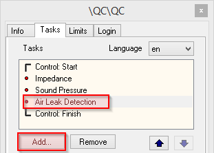
Click the Add… button on property page Tasks
Choose the KLIPPEL task script ald.task.klb
The default location is (English Windows OS version):
%ProgramData%\Klippel\QC\Scripts\Klippel\QC\Modules
The ALD task will be added to the list of measurement tasks.
Note
Adding a new task always requires creating new reference units. You have to confirm that you want to delete all reference measurements, if limits exist in your test.
Adding a QC ALD Operation (R&D System)#
If you are operating the ALD in the KLIPPEL R&D System framework, you may add an ALD test by using the provided operation template
Create or open a KLIPPEL database
Add a new operation by using the operation icon or
Select ; you may enter ALD in the filter input field to quickly find the template
Choose a name and click OK to create a new QC operation with and ALD task
Click Run
 to log in
See dB-Lab Software Manual for more information.
Performing a First ALD Measurement#
This is a step-by-step guide about performing a first ALD measurement.
Setting up the Hardware#
Running the ALD task is possible with many different hardware configurations using the KLIPPEL QC Production Analyzer (PA), the KLIPPEL Analyzer 3 (KA3) or even digital audio devices (DUT) or 3rd party audio interfaces. The minimal requirements are
At least one microphone input channel
At least one line output channel for testing active devices
A PA or KA3 with internal or external power amplifier for testing passive devices
For normal operation with the KLIPPEL QC System, please refer to: QC User Manual section Connecting the System.
Your First ALD Measurement#
After adding the new ALD Task to your QC test, you can start with your first measurement. In Engineer mode you can select the ALD task and edit the measurement parameters.
Set proper stimulus settings according to your test unit and check the voltage setting before running the ALD. Refer the following section for more information on basic settings.
Click on the green Start button in the control panel to start your first measurement
Basic Settings#
Stimulus#
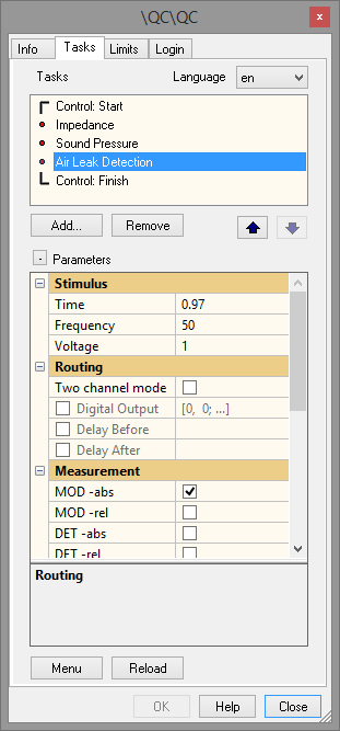
The category Stimulus provides the settings for the stimulus and system type properties.
- Time
With this option the measurement time can be selected from a list of predefined values. Only discrete values are provided due to the requirements of the signal analysis. A long measurement time improves the sensitivity but increases the processing time. The given values include a default pre-loop time to achieve steady-state conditions before the measurement starts.
- Frequency
This parameter defines the single tone stimulus frequency. It should be set below the driver’s resonance frequency for high membrane excursion in case of measuring a closed speaker box or a driver in free air. See Finding the Optimal Stimulus Frequency for details regarding vented boxes.
- Voltage/Level
Here the RMS voltage or digital level of the stimulus signal is specified. A high sound pressure should be achieved in the device under test in order to stimulate leak air flow and other defects.
Depending on the parameter Output in the category Routing this value either defines the voltage at the speaker terminals for passive systems (Speaker 1, Speaker 2) or at the selected Line output of the analyzer or 3rd party audio interface for active systems, respectively .
Warning
A too high voltage can damage your speakers!
Routing#
The category routing provides the settings for the input and output routing as well as digital output configuration.
Two Channel Mode#
The ALD offers two operational modes. In the default mode one dedicated measurement channel is used. The second channel may be used for ambient noise measurement.
Activating Two channel mode offers two equal and independent channels for parallel measurement with two test microphones. Although not directly measured, limited ambient noise detection is provided using Noise Post-processing. Two channel mode is useful for larger test objects to cover a wider test angle with two microphones at different positions. A measurement enclosure providing proper ambient noise attenuation should be used in any case.
Note
In a noisy environment it is recommended to use the default measurement setup with an additional ambient noise microphone due to the sensitivity of the ALD task. In case you are using a KA3 or 3rd party audio interface, the Signal Sharing feature is the recommended approach for multi-microphone testing while keeping full noise disturbance detection. Also, a multiplexer can be used if the number of input channels is limited. See Measuring Large Objects for further details.
Viewing ALD Results#
The Summary window shows the results measured by the ALD Task. For better overview, the provided measures are divided and displayed in measure groups.
The available results in default single channel mode are:
MOD ulation:
MOD abs (abs olute MOD ulated noise)
MOD rel (rel ative MOD ulated noise)
DET erministic:
DET (L)abs (abs olute DET erministic L eak distortion)
DET (L)rel (rel ative DET erministic L eak distortion)
DET abs (abs olute DET erministic distortion)
DET rel (rel ative DET erministic distortion)
Rand om (Random or sporadic distortion)
The table below gives a short explanation of the single-valued parameters measured by ALD. See Definition of Results for further details.
- MODabs
The MODabs represents the absolute peak SPL of amplitude modulated (AM) noise. Thus, it perfectly quantifies turbulent flow noise as caused by leaks and other defects causing periodic noise (e.g. coil rubbing). MODabs It should be used in conjunction with the MODrel as a qualitative measure, because MODabs can be influenced by other noise sources.
- MODrel
The \(MOD_{\text{rel}}\) is a relative measure derived from \(MOD_{\text{abs}}\) for qualitative evaluation. The amplitude of the modulation envelope is related to the noise floor to give information about the defect symptoms. It may be compared to the modulation index in amplitude modulation. As an absolute indicator for modulated noise it is useful to detect leakage and similar defects even without reference limits. Values significantly above the minimum of 0 dB (default: 5 dB) indicate turbulent leak noise or other defects causing semi-random distortion. Thus, it verifies the quantitative results of \(MOD_{\text{abs}}\).
- DET(L)abs
The \(DET(L)_{\text{abs}}\) is a high-level measure exploiting specific harmonic distortion caused by air leaks. It is useful for very small leaks which do not generate flow noise. It represents the averaged deterministic distortion peak SPL. In contrast to the MODulation measures, DET(L) is a unique symptom for small leaks with weak air flow. Thus, it cannot be masked by port turbulences und provides high sensitivity to identify leaks.
- DET(L)rel
The \(DET(L)_{\text{rel}}\) is derived from \(DET(L)_{\text{abs}}\) as a relative level measure. It is comparable to a crest factor of the average leak distortion.
- DETabs
The \(DET_{\text{abs}}\) is a measure for high order harmonic distortion. It is a measure for deterministic (strictly periodic) Rub&Buzz distortion as caused by hard limiting or loose wires. The measure represents the peak value of the deterministic distortion on an absolute scale in dB(SPL).
- DETrel
The \(DET_{\text{rel}}\) is derived from \(DET_{\text{abs}}\) as a relative level measure. It represents the crest factor of high-order harmonic distortion (e.g. Rub&Buzz).
- Random
Random is a measure for impulsive distortion which happens sporadically (e.g. caused by loose particles). It represents the peak SPL of non-deterministic distortion.
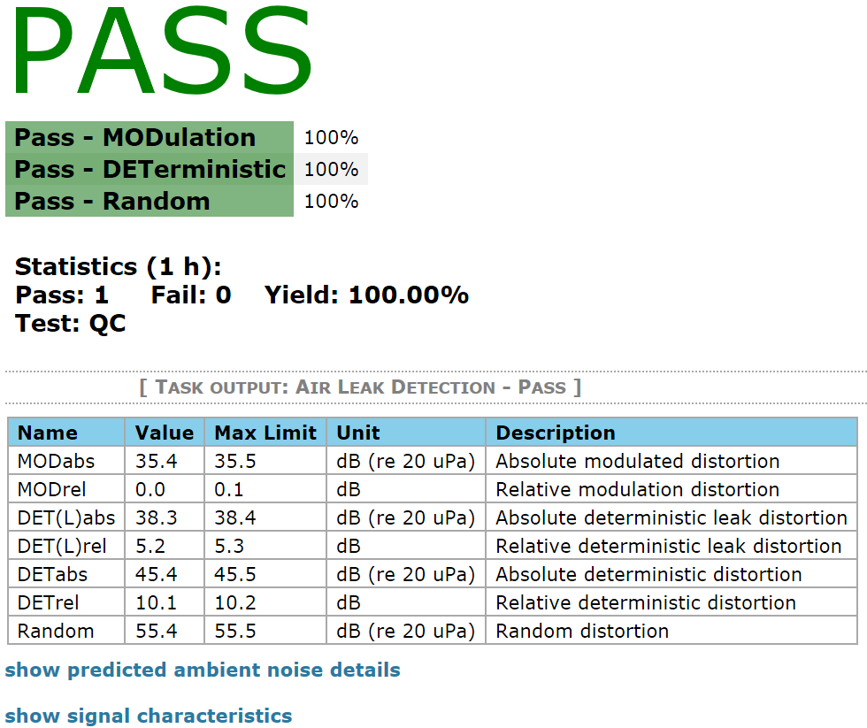
The summary window below is taken from a measurement with limits. It directly shows whether the speaker passed or failed the tests. To pass the test means that the measured parameters are all within the defined limits. In case any of the above-mentioned measures failed the corresponding measure group will be highlighted red and details about the failed measure are specified as a suffix behind the group name.
The result table below the group verdicts gives details about the single results, which are the sub-elements of measure groups MODulation, DETerministic and Random.
See Measurement with Limits for creating own limits.
Working with the ALD Task#
This section offers a short overview about working with limits and ambient noise detection.
Limits#
In the QC Engineer mode, the user is enabled to set tolerance limits for the QC test using Limit Calculation Mode.
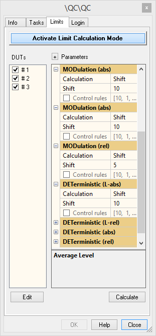
While this mode is enabled, each measured and selected driver will become a reference unit and the limits for further measurements are derived from these units.
Measurement with Limits#
If limits have been set, the measurement results of each test are checked against them to derive a PASS/FAIL decision.
Open a test in Engineer mode and choose proper setup parameters.
Select Limits tab in Properties window and click Activate Limit Calculation Mode.
Now start the measurement by clicking the Start button in the control window. An arbitrary number of reference units/measurements can be collected, as long as the Limit Calculation Mode is activated.
In this example shown in the screenshot, three references have been measured.
When the number of reference units is sufficient, click Calculate or deactivate the Limit Calculation Mode by clicking Activate Limit Calculation Mode. The tolerance limits for valid DUTs are now calculated according to the Parameters and displayed in the summary window as shown below.
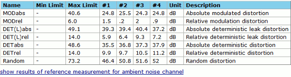
All following measurements will be checked against these limits.
Note
Absolute limits can be calculated and applied also without reference DUTs.
Reference DUT Check#
To ensure the validity of the calculated limits and to identify possible defect reference units, all measured reference DUTs are checked against the calculated limits automatically after deactivating Limit Calculation Mode. In case any reference DUT fails the check, the summary window shows additional information as shown below.
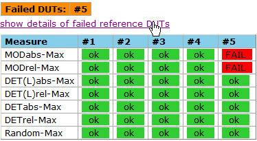
All failed reference DUT’s are listed. To identify the failed measure a hidden table shows the single verdicts. To solve this conflict, go back to Limit Calculation Mode and either remove the concerning reference unit from the reference DUT list or readjust the limit calculation settings.
Testing your First Device#
Once you have created limits, you may run a test to obtain the test verdict. If the results are within the tolerances the Summary window will show PASS.
If the measurement results exceed any limit, the relevant measure group will be highlighted red in the Summary window. This results in an overall FAIL decision. The suffix of the group measure name shows which measure failed the test. Additionally, the failed measure name is highlighted red in the result table below the verdicts.
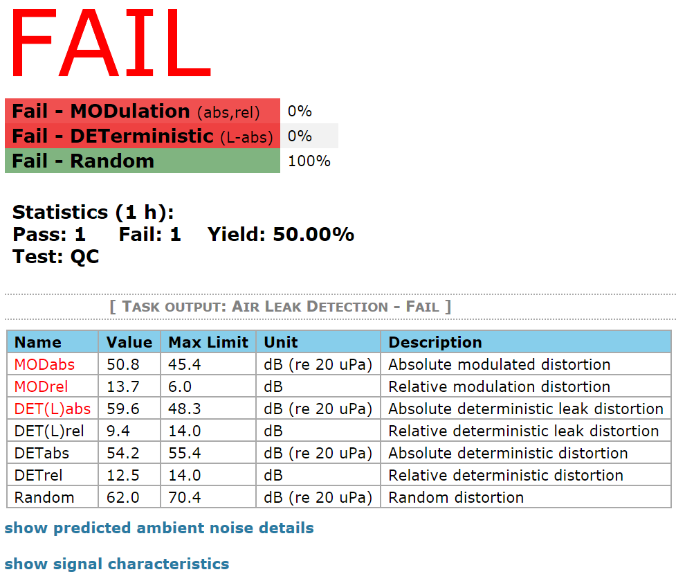
If activated, the measurement results are saved as individual files and a summary log-file is created. See the QC User Manual section Storing Results for detailed information.
Ambient Noise Detection#
If Noise Monitoring is active and one or more measures failed due to noise corruption, the overall task verdict will be NOISE as shown below. The label - Noise will be added to the corrupted measure group to identify partly corrupted measurements.
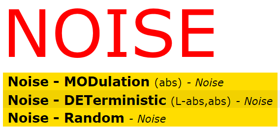
See Ambient Noise Detection for further information.
Changing Limits#
In ALD task limits for the following measures can be defined:
- MODabs
absolute, shift, statistic
- MODrel
absolute, shift
- DET(L)abs
absolute, shift, statistic
- DET(L)rel
absolute, shift
- DETabs
absolute, shift, statistic
- DETrel
absolute, shift
- Random
absolute, shift, statistic
Type of limit#
- Absolute
Gives absolute values for the lower upper (\(=\) max) limit. This value is independent of the average value of the reference units.
- Shift
The shift value is added to the average value of the reference units for the upper limit.
- Statistic
Sigma is the standard deviation factor for a uniform distribution of measurement values. Statistic limit calculation is only reasonable for more than ten measured references.
For additional information about limit calculation mode see QC Manual section Limit Calculation.
Optimizing your ALD Task#
Finding the Optimal Stimulus Frequency#
The performance of leak detection strongly depends on the proper stimulation of leakage symptoms (air flow). A sufficiently high air pressure at the leak is necessary. In case of measuring drivers in free air or closed loudspeaker cabinets, the frequency is rather uncritical, as long as it is chosen below the resonance frequency in order to guarantee high air compression through high displacement.
Choosing a proper stimulus frequency for vented system requires considering different aspects. Turbulences caused by ports mainly occur close to its resonance frequency because of maximal particle velocity. Depending on the port characteristic the emitted flow noise can mask turbulent leak noise in case of an actual defect. This means an effective loss of sensitivity. Although the box pressure is maximal at the port resonance frequency, it may be better to choose a slightly higher frequency (e.g. 1/3 octave) to minimize the influence of probable port noise. Of course, the ALD can also be used for quality control of port noise itself.
Alternatively, it is recommended to seal the port during ALD measurement. This prevents measuring port noise and guarantees high box sound pressure (below the system’s resonance frequency). In this case make sure that port sealing itself is not leaking.
The discussed aspects should be considered depending on the DUT characteristics and the measurement goal.
Note
Measuring Rub&Buzz distortion caused by the driver can be very frequency dependent. Measuring DETerministic distortion does not replace sweep-based Rub&Buzz measurement.
Setting the Amplitude of the Stimulus#
Use a sufficiently high stimulus voltage to excite loudspeaker defects and air leakage flow noise as shown in the example below. The absolute threshold level depends on the DUT and leak properties.
The example plot shows the relative MODulation vs excitation voltage for a leaky and a sealed speaker. The minimal leakage detection threshold voltage for this speaker is 1 V.
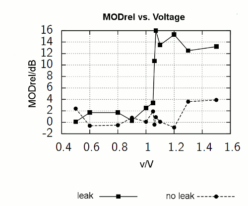
Note
Air leakage flow noise requires a sufficiently high stimulus voltage to be excited, but the distortion level does not necessarily rise with the stimulus level. Measuring deterministic leak distortion (\(DET(L)_{\text{abs}}\) , \(DET(L)_{\text{rel}}\)) does not require high stimulus levels.
Warning
Measuring vented box systems may also produce modulated noise caused by turbulences at high voltages or close to the port’s resonance.
Ambient Noise Detection#
Due to the high measurement sensitivity, the ALD task provides ambient noise detection in order to ensure valid measurements. Full functionality is only available in default single channel mode using one test microphone and one dedicated ambient noise microphone in at least one-meter distance to the DUT as shown in the figure below.
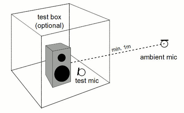
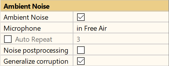
The setup parameters for ambient noise detection are available in task parameter section Ambient Noise. Activate Noise Monitoring to enable the feature.
It is crucial to adjust the settings correctly according to your physical test setup. The position of the ambient noise microphone is set by parameter Microphone. In case a test enclosure is used, make sure to select in Box or Custom (see next section for more information).
Note
Ambient noise monitoring requires limits calculated from reference DUTs.
The default microphone input channel for noise monitoring is Mic2. However, the input routing may be set manually or automatically depending on the global routing settings in Control:Start task. For more information please refer to QC User Manual section Input Routing for Klippel Hardware.
Custom Test Box Attenuation#
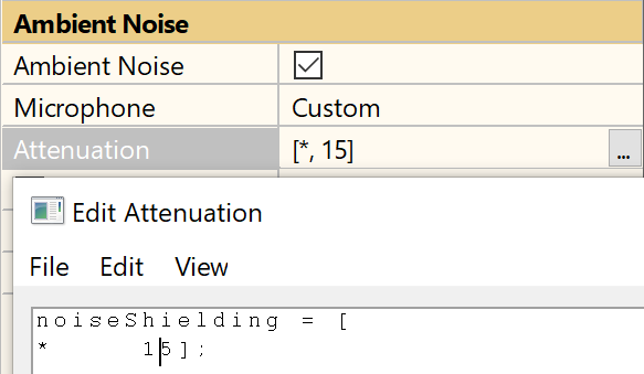
The default box attenuation applied in mode Microphone – in Box is 15 dB for all frequencies (above minimal analysis frequency, normally 1 kHz). In case your test box provides better damping, you may enter a custom box attenuation curve as shown below in case a measurement enclosure is used for ambient noise shielding. See Acoustical Requirements for further details.
Note
Due to the high sensitivity of the ALD it is recommended to use a measurement enclosure providing maximal sensitivity and to prevent corruption and time-consuming auto repeat in a noisy environment.
Noise Post-processing#
In addition to ambient noise measurement the ALD offers noise detection without an additional microphone based on interpreting MODulation measures (consistency check). It works independently for every measurement channel if limits have been defined and the option is enabled in parameter category Ambient Noise.
The concept is based on the assumption that both the absolute level (\(MOD_{\text{abs}}\)) and the modulation symptom level (\(MOD_{\text{rel}}\)) have to correlate in case of a defective DUT. Any disturbance, which is not correlated to the stimulus, will not produce modulation symptoms (\(MOD_{\text{rel}}\)). Thus, an independent increase in \(MOD_{\text{abs}}\) can be interpreted as ambient noise.
Note
Both \(MOD_{\text{abs}}\) and \(MOD_{\text{rel}}\) measures have to be activated for noise post-processing. Noise post-processing is mainly meant for identifying ambient noise corrupted measurements without the use of an ambient microphone. Nevertheless, it is highly recommended to use a dedicated noise microphone. Although noise post-processing is a simple and effective tool, it requires properly set limits. If \(MOD_{\text{abs}}\) limit is too sensitive in comparison to \(MOD_{\text{rel}}\) , noise post-processing may produce wrong noise verdicts due to misinterpretation. Please raise the limit in this case (check the Noise Details table in summary window). Using the default limit setup should prevent this situation.
Noise Details#
To see further details about the noise detection of the last performed measurement open the noise details table by clicking show ambient noise details in the summary window as shown below. The single noise verdicts can be checked here.
The predicted noise levels for the individual measures at the test microphone position as well as the applied limits are also shown in the table, if an ambient noise microphone is used and activated.
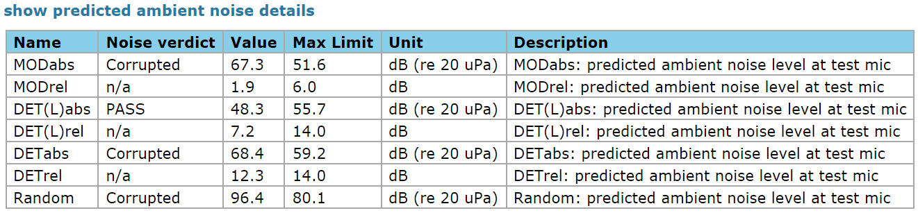
In case only Noise Post-processing is activated, the table will only contain noise verdict information.
Auto Repeat#
Activating auto repeat forces corrupted measurements to be repeated automatically. The maximal number of repetitions is specified by the task parameter Ambient Noise - Auto repeat.
Acoustical Requirements#
For optimal performance of the ALD, the following conditions should be taken into account.
Noise Shielding#
The ALD requires a high acoustical sensitivity to detect leakage symptoms flow noise. Therefore, the acoustical conditions are crucial for best performance. Although ambient noise corruption can be detected reliably using an ambient noise microphone (see Ambient Noise Detection), a test enclosure should be used to provide noise attenuation.
This ensures high sensitivity (low noise floor), precise results in a noisy environment and fast measurement without auto repeat. Even if a test enclosure is used, external noise may falsify the results. Therefore, ambient noise measurement should be employed in any case.
Activating Noise monitoring while measuring in free air using microphones with equal noise levels can lead to a loss of sensitivity for all absolute distortion measures through higher noise level. In this case a warning is displayed after limit calculation showing the maximal sensitivity loss in dB and the corresponding measure. The tolerance limits are widened by this value.

To prevent this, follow the instructions displayed.
How to Obtain the Box Attenuation#
When testing with ambient noise detection, it is important to know, how much the production noise is attenuated by the measurement enclosure in order to predict the possible impact on the test results. Thus, the transfer function from the ambient microphone to the near field test microphone has to be known.
To determine the attenuation curve versus frequency of a measurement enclosure, please see section How to Measure Box Attenuation? in QC Manual.
However, the effective mean attenuation for the ALD Task can be measured using the ALD Task passively in combination with external excitation. High-level broadband noise can easily be generated by clapping hands or by other means causing percussive noise.
For proper results the measurement should be set up as shown below. Both microphone position should be of the same type (equal noise level) and have approximately the same distance to the noise source of at least 2 m.
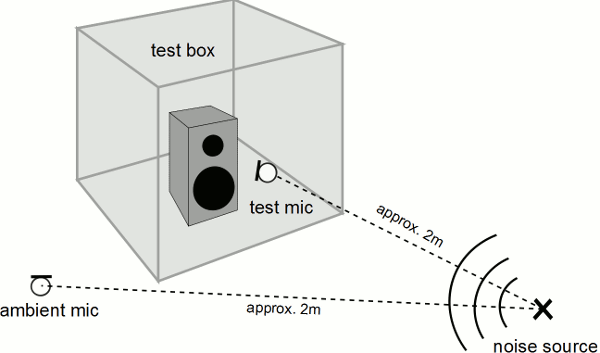
To setup the ALD Task, follow this sequence:
Create a new test and add the ALD Task.
Adjust the parameters as shown below.
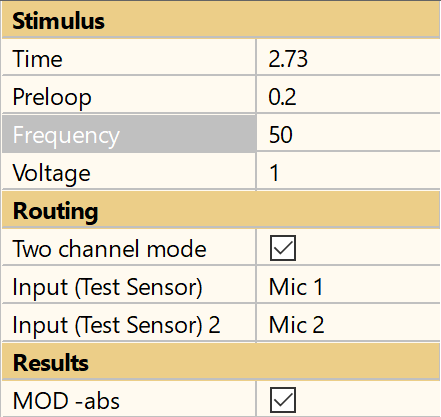
Activate Limit Calculation Mode.
Ensure that the production noise is minimal and perform a first measurement. Both channel’s MODabs values should have roughly equal levels.
Perform a second measurement while broad band noise is present
Leave Limit Calculation Mode to display both measurements’ data. Ignore the warning that the second reference DUT failed. Now there are two sets of data. The second set should be at least 20 dB above the first representing the noise floor. The difference between channel 2 (ambient mic) and channel 1 (test mic) of the second set represents the mean box attenuation in the analyzed frequency range (2 kHz respectively 10 \(\cdot f_{\text{stim}}\) to \(\frac{f_{\text{sample}}}{2}\)). In the displayed case the attenuation would be roughly 25 dB.

The determined attenuation can now be entered in the property field Attenuation in any ALD Test choosing Microphone – Custom in the property page as shown below
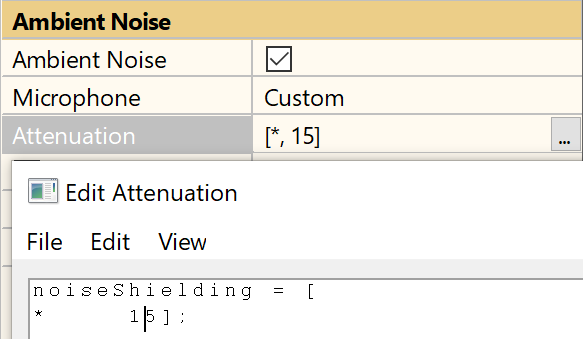
Making the Measurement as Fast as Possible#
The total test time is a sum of the measurement time (incl. default pre-loop) and the calculation time of the results. The calculation of the results can be performed while the next task (e.g. SPL task) is running, as long as the auto repeat and digital output routing is deactivated.
The measurement time is not a very critical parameter for measuring absolute sound pressure level of defect symptoms (e.g. leak noise). However, a longer measurement time can yield better results due to averaging for the relative symptom measures (e.g. \(MOD_{\text{rel}}\)).
Measuring Large Objects#
The performance of the ALD using the standard hardware setup with one test microphone depends on the geometry and size of the measured object. Assuming that the location of possible leaks in the DUT is not known in advance, the microphone position will influence the results.
The main difficulty is less the measurement distance, but shadowing effects (e.g. edges or opposing surfaces). Leak noise mainly contains high frequency components which are shadowed by any obstacle, easily. To minimize such effects for large test objects, it is recommended to use more than one measurement microphone. Good performance can be achieved by arranging an array of microphones (e.g. 4 mics) around the DUT. Up to four microphone channels may be measured simultaneously with KA3 or 3rd party audio interfaces. If the number of microphone input channels is limited (e.g. with Production Analyzer) a KLIPPEL microphone multiplexer can be used to measure up to eight microphones sequentially with parallel ambient noise monitoring using the second microphone input channel. See the hardware specification A8 Multiplexer for more information.
Alternatively, both available microphone channels can be used to measure the DUT simultaneously activating Two Channel Mode. In this case, only Noise Post-processing is available. Therefore, a proper acoustical shielding should be provided to minimize ambient noise impact.
Air Leak Detection in SPL Task#
Overview#
The standard Sound Pressure (SPL) task is based on a sine sweep measurement. Typical air leaks show their specific symptoms (see section Definition of Results for details) usually in a certain frequency range where the sound pressure pushing the air through the leaks is high. The bandwidth of this range is about one octave or more, if the test level is sufficiently high.
Thus, the leak symptoms can also be found from a part of a sweep rather than from a single sine tone (which is used in the separate Air Leak Detection Task). The processing method is similar in both implementations; the derived results are very similar as long as leak symptoms are present in the chosen bandwidth.
How to Use Leak Detection in the SPL Task#
Licensing#
To operate Leak Detection in the SPL Task, a license for both the ALD and SPL is required. The leak detection feature can be combined with all other modules related to the SPL task.
Enable ALD Measures#
On property page Tasks select the Sound Pressure task and open the section Results from the parameter list.
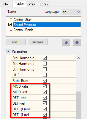
Enable the measures required for your application. More information about the usage and benefits of each measure can be found in the section Definition of Results.
If at least one ALD measure is enabled, you can select the center frequency and bandwidth for the frequency range, where leak symptoms are searched.
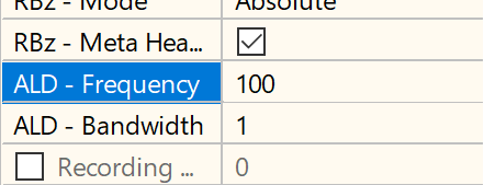
Choose a range, where the sound pressure causing leak symptoms (turbulent air flow) is high. You may use the manual sweep option to verify the range using a defective DUT showing leak symptoms.
For transducers and closed box systems the preferred setting for the center frequency is around the resonance, where the displacement and consequently the pressure in the box or below the dust cup is highest. For more details, also refer to section Optimizing your ALD Task for stimulus and level selection.
Measurement Time#
Air Leak Detection requires a minimal number of periods in the specified frequency range to extract reliable results. In addition to the specified frequency range some more bandwidth is required for processing (fading in and out).
If the measurement time is too short, ALD results cannot be calculated and an error message appears in the summary chart. See also section Errors and Warnings.
The required time depends on the chosen bandwidth and test sweep configuration.
Example#
For a full band sweep from 20 Hz to 20 kHz with the default sweep speed profile [1000, 5], a center
frequency of 100 Hz and a bandwidth of one octave, a total test time of 0.6 s is required.
Especially testing subwoofers with a low frequency test range for leak symptoms, a longer test duration is required. In this case, it also helps to decrease the lower end of the sweep frequency.
Note
Make sure you have sufficient SNR of the frequency response in the defined frequency range. Especially when testing low frequency transducers in free air there might be problems with poor SNR due to the acoustic short cut effect at low frequencies. A test enclosure is recommended.
Both, up- and down sweeps are supported.
Limits#
Limits can be calculated using reference DUTs and limit parameters or can also be imported from external limit files. See QC User Manual section Limit Calculation for more information.
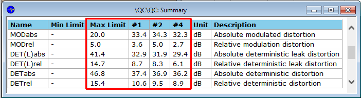
The limits and results of all used reference DUTs are listed in the Summary window after calculating the limits:
Results#
In the Summary chart a table with the results and limits are shown:
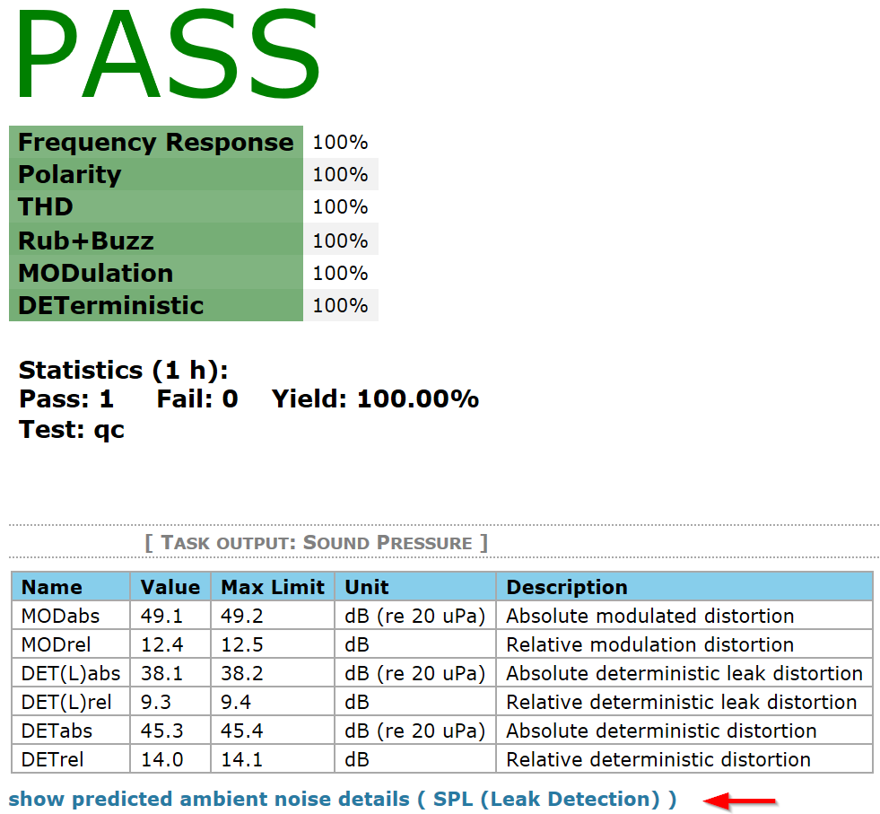
If the ambient noise detection or PNI – Production Noise Immunity option is enabled, the details of noise levels can be investigated using the marked link in the screenshot above. Here the distance of measured noise to the noise limit can be monitored.
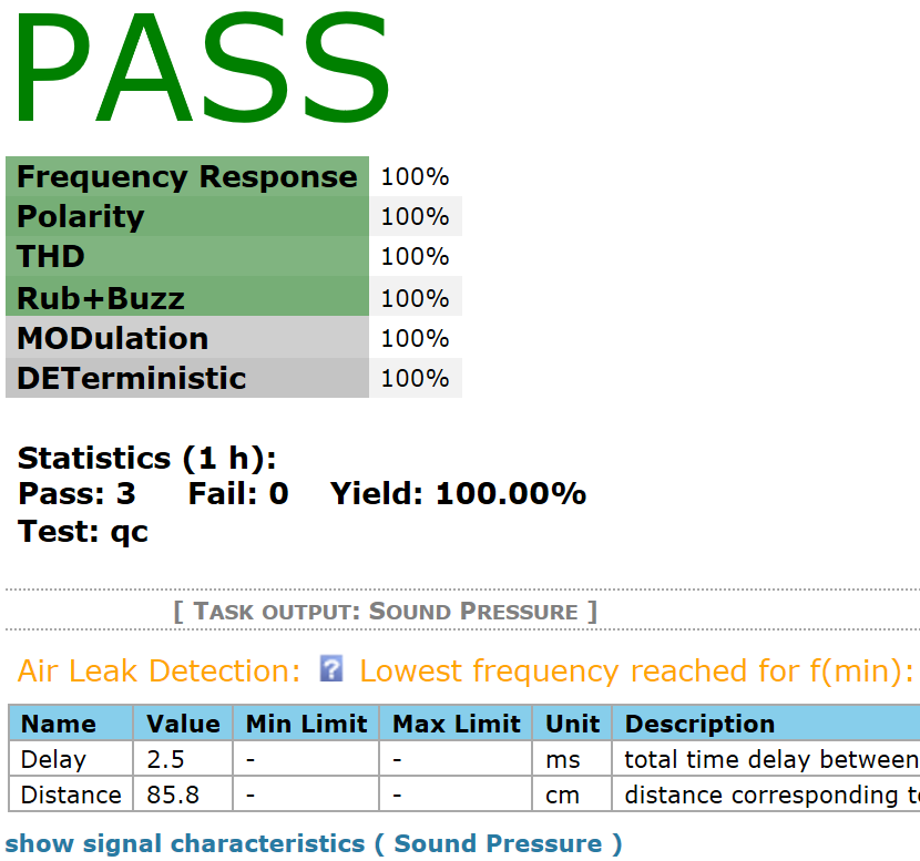
In case of noise problems (DUT not connected, SNR too low, ambient noise too high) the results cannot be calculated. A warning is displayed and the verdicts are set to VOID because no result can be compared against the limits.
Error and Warning Messages#
All errors are marked with a help symbol which provides fast access to the manual (context help).

Errors and Warnings#
Lowest Frequency Reached#
The bandwidth (defined by Leakage Center Frequency and Leakage Bandwidth) for leak detection defines the upper and lower frequency limit. In addition to this range for internal signal processing (lead in and lead out) further bandwidth is required.
Especially if
test levels is low
the DUT is not connected properly
test is performed in free air without a box/baffle (acoustic shortcut)
a minimum signal to noise ratio of the recorded response cannot be obtained. In this case the leakage results are not calculated and a warning is issued. The verdict for the leak results is VOID.
If this warning is persistent, the following causes may apply:
- Cause:
The required Leakage Bandwidth is too large for the given setup or the required Leakage Center Frequency is too low.
- Solution:
- - Decrease the bandwidth or increase the Leakage Frequency (in Processing section).- Lower the minimal sweep frequency (in Stimulus section).- Increase the measurement time. This extends the available response useable for leak detection analysis (in Stimulus section).
Highest Frequency Reached#
The bandwidth (defined by Leakage Center Frequency and Leakage Bandwidth) for leak detection defines the upper and lower frequency limit. In addition to this range for internal signal processing (lead in and lead out) further bandwidth is required.
The parameter check on the property page for leak frequency and bandwidth is estimating the valid range. Depending on the exact values of test time, speed profile, start and stop frequencies the actual high frequency limit can be beyond the measured sweep range.
- Solution:
- - Decrease the upper leakage band limit by reducing the leak frequency or bandwidth.- Increase the upper measurement frequency range
Cannot Calculate Leak Results#
- Cause:
The center frequency Leak frequency in section Noise Post-processing on the property page Tasks is beyond the defined sweep range.
- Solution:
- - Extend the sweep frequency range that it covers the requested leak detection bandwidth- Modify the frequency range used for leak detection to be included in the measurement bandwidth
Bandwidth Limited (Poor SNR)#
Leak Detection results cannot be derived from the measurement since the Signal to Noise Ratio (SNR) is too low. Possible causes are low level measurements or transducer tests in free air (acoustical shortcut degrades the level of the fundamental and hence the SNR at low frequencies considerably).
Note
In case of a disconnected DUT or a transducer with an open circuit defect, this warning is normal. It indicates that the algorithm cannot detect the response delay.
- Solution:
- - Increase test level, if the warning appears sporadically using a normal DUT with acoustical output (no open circuit).- Ensure sufficient SNR of frequency response especially at low frequencies. Use a test baffle or box to avoid acoustic cancellation effects.
Too High Bandwidth Requested#
Leak Detection results cannot be derived from the measurement. There are two causes possible:
- Cause:
The measurement bandwidth (frequency range) is very close to the leak detection bandwidth. For leak detection analysis, more bandwidth than requested is required for lead in and out means.
- Solution:
Increase the measurement bandwidth, especially at the lower end.
- Cause:
The measurement is noisy and the SNR is low. Possible causes are low level measurements or transducer tests in free air (acoustical shortcut degrades the level of the fundamental and hence the SNR at low frequencies considerably).
- Solution:
Increase test level or use a test baffle or box to avoid acoustic cancellation effects.
ALD – Reference#
ALD Task – Parameters#
The table below lists and describes all available task parameters of the ALD task. These parameters are necessary to customize the measuring task.
Configuration#
- Import Settings
Activate setup and limit parameter import from external file. Also see section ALD in SPL Task - Settings & Limit Import for a list of parameter import names. Only available if Import Settings in Control task is activated.
- Settings file
file path of settings file, absolute path via file dialog or relative path (test folder) may be specified. Only shown if Import Settings is active.
Stimulus#
- Time
Measurement time (drop-down list with discrete values), pre-loop and fade-out time not included
- Preloop
duration of stimulus pre-excitation before measurement starts to ensure steady-state conditions
- Frequency
Stimulus frequency, Value is adjusted to a discrete frequency defined by signal analysis
- Voltage
RMS stimulus voltage at speaker terminals or respectively at Line output of the analyzer or output device (depends on output routing settings)
- Stimulus level
stimulus peak level for digital output device
Routing#
- Custom File for Import
path of task-specific custom wave file for processing (raw data import), (only available in case of wave file processing)
- Source Task
name and subtitle of ALD task used as signal data source for shared input signals (e.g. for multi-channel testing), only visible if Execution - Allow signal data sharing is activated in Control Task. See Signal Sharing for more information.
- Output
- Options: Speaker 1,2 (loudspeaker terminals); OUT 1, 2, 1+2
Select output of analyzer or playback device. The test voltage/level is specified at selected output (only available if global output routing is set to controlled by task)
- Speaker 1 connect
Connects speaker 1 to power amplifier output
- Speaker 2 connect
Connects speaker 2 to power amplifier output
- Output Channel
select output channel(s) of playback device (only available for 3rd playback audio device output and if global Output is set to controlled by Task)
- Two channel mode
Activates parallel measurement mode with two test microphones; ambient noise measurement with a dedicated microphone is not available in this mode
- Input (Test Sensor)
- Options: Mic 1, Line 1, Mic 2, Line 2, Mic linked to Speaker, Line linked to Speaker, Mic linked to Speaker (swapped), Line linked to Speaker (swapped)Select input channel for measurement channel 1. (only available if global input routing is set to controlled by task)
- Input (Test Sensor) 2
Select input channel for measurement channel 2. Choices are same as for other input. (only available if global input routing is set to controlled by task)
- Input (Noise Sensor)
- Options: Choices are same as for other input.
Select input channel for ambient noise monitoring. (only available if Noise Monitoring measurement is active and global input routing is set to controlled by task)
- Test Sensor Input Channel 1
select channel of capture device or wave file for primary test sensor signal (Only displayed with 3rd party capture device or Execution Mode - Load Input Signals and if Test Sensor Input is set to controlled by Task)
Note
for re-processing exported wave file data (see Qc Manual section Save Input Signals) use channel #1.
- Test Sensor Input Channel 2
select channel of capture device or wave file for secondary test sensor signal (Only displayed with 3rd party capture device or Execution Mode - Load Input Signals)
Note
for re-processing exported wave file data (see Qc Manual section Save Input Signals) use channel #2.
- Noise Sensor Input Channel
select channel of capture device or wave file for noise sensor signal (Only displayed with 3rd party capture device or Execution Mode - Load Input Signals and if Noise Sensor Input is set to controlled by Task)
Note
for re-processing exported wave file data (see Qc Manual section Save Input Signals) use channel #2.
- Digital Output
- Options: Format 1: [Value1, Mask1; Value2, Mask2; …]; Format 2: [Value1; Value2; …]
Bit mask for digital output (GPIO) of KLIPPEL analyzer (e.g. for multiplexer control), pins are set before test. rows correspond to pins 24, (11), 5, 17, 4, 16, 3, 15, 2
- Delay Before
Set delay before measurement starts (after GPIO setting, if requested)
- Delay After
Set delay after measurement (before next task starts)
Results#
- MOD -abs
Measure absolute modulated distortion MODulation (abs) (modulation envelope peak level); indicates turbulent flow noise caused by air leakage (level)
- MOD -rel
Measure relative modulated distortion MODulation (rel) (modulation ratio); indicates flow noise caused by air leakage (symptom intensity)
- DET -(L)abs
Measure absolute deterministic leak distortion, DETerministic (L-abs) (peak level); indicates air leakage (level)
- DET -(L)rel
Measure relative deterministic leak distortion, DETerministic (L-rel) (modified crest factor); indicates air leakage (impulsiveness)
- DET -abs
measure absolute deterministic distortion, DETerministic (abs) (peak level of averaged high-order harmonic distortion); indicates periodic Rub&Buzz (level)
- DET -rel
Measure relative deterministic distortion, DETerministic (rel) (crest factor of averaged high-order harmonic distortion); indicates periodic Rub&Buzz (impulsiveness)
- Random
Measure absolute Random distortion (peak level of randomly occurring distortion); indicates loose particles
Processing#
- Min Frequency
- Unit: Hz
cut-off frequency of high-pass pre-filter; Applied to input signal before signal analysis
- DET - Highpass
minimal harmonic order (multiples of stimulus frequency) for deterministic distortion measurement
- Input gain 1
Input gain for KLIPPEL analyzer inputs corresponding to Mic1/Line1
Note
the effective range and available gain steps depend on used analyzer/card, please refer to hardware specification.
- Input gain 2
Input gain for KLIPPEL analyzer inputs corresponding to Mic2/Line2
Note
the effective range and available gain steps depend on used analyzer/card, please refer to hardware specification.
- Recording Delay
Fixed delay of captured signal relative to generator (in addition to hardware or measured delay)
Ambient Noise#
- Noise Monitoring
Activate ambient noise measurement and/or noise post processing (if requested); use optional ambient noise microphone for full performance (see Ambient Noise)
- Microphone
- Options: In Free Air, In Box (attenuation 15 dB), Custom (use attenuation curve)
Position/location of test microphone; Specify the measurement setup to apply box attenuation, if a measurement enclosure is used (available if Noise Monitoring is active)
- Attenuation
- Frequency in Hz, Attenuation in dB
Acoustical attenuation of ambient noise at near field mic due to box enclosure (attenuation vs. frequency (available if Noise Monitoring is active and Microphone – Custom is selected)
- Auto Repeat
Measurement is repeated automatically in case measurement is corrupted by ambient noise (available if Noise Monitoring is active)
- Noise postprocessing
Activate ambient noise postprocessing, Checks the consistency of the MODulation measures to identify corrupted measurements; This feature should only be used if no ambient noise mic is available
- Generalize corruption
All FAIL verdicts are invalidated, if at least one measure was identified as corrupted by ambient noise This option is active by default to guarantee valid measurement results. (available if Noise Monitoring is active)
ALD Task - Settings & Limit Import#
Most task properties (setup and limit parameters) are available for import from an external parameter file during login.
Setup Parameters#
The following table lists the IDs of the parameters and the corresponding text labels (English version) as shown in the user interface. Only use the IDs for import.
Note
The parameters for External Synchronization are identical in all tasks. Please refer to ref:syn-manual.
- Time
- Type: numerical value (discrete values)
Parameter Name (EN) |
ID (in parameter file) |
|---|---|
Time |
|
|
|
|
|
|
|
|
|
|
|
|
|
- Preloop
- Type: numerical value
Parameter Name (EN) |
ID (in parameter file) |
|---|---|
Preloop |
|
- Frequency
- Type: numerical value
Parameter Name (EN) |
ID (in parameter file) |
|---|---|
Frequency |
|
- Voltage
- Type: numerical value
Parameter Name (EN) |
ID (in parameter file) |
|---|---|
Voltage |
voltageAtOut (output routing)voltLev_dBFS (ext. audio device) |
- Custom File for Import
- Type: string
Parameter Name (EN) |
ID (in parameter file) |
|---|---|
Custom File for Import |
|
- Two Channel Mode
- Type: bool
Parameter Name (EN) |
ID (in parameter file) |
|---|---|
Two Channel Mode |
|
- Output (Routing)
- Type: string
Parameter Name (EN) |
ID (in parameter file) |
|---|---|
Output (Routing) |
|
|
|
|
|
|
|
|
|
|
|
- Speaker 1 Connect
- Type: bool
Parameter Name (EN) |
ID (in parameter file) |
|---|---|
Speaker 1 Connect |
|
- Speaker 2 Connect
- Type: bool
Parameter Name (EN) |
ID (in parameter file) |
|---|---|
Speaker 2 Connect |
|
- Output Channel
- Type: integer vector
Parameter Name (EN) |
ID (in parameter file) |
|---|---|
Output Channel |
|
- Input (Test Sensor)
- Type: string
Parameter Name (EN) |
ID (in parameter file) |
|---|---|
Input (Test Sensor) |
|
|
|
|
|
|
|
|
|
|
|
|
|
|
|
|
|
- Input (Test Sensor) 2
- Type: string
Parameter Name (EN) |
ID (in parameter file) |
|---|---|
Input (Test Sensor) 2 |
|
|
|
|
|
|
|
|
|
|
|
|
|
|
|
|
|
- Input (Noise Sensor)
- Type: string
Parameter Name (EN) |
ID (in parameter file) |
|---|---|
Input (Noise Sensor) |
|
|
|
|
|
|
|
|
|
|
|
|
|
|
|
|
|
- Test Sensor Input Channel 1
- Type: numerical value
Parameter Name (EN) |
ID (in parameter file) |
|---|---|
Test Sensor Input Channel 1 |
|
- Test Sensor Input Channel 2
- Type: numerical value
Parameter Name (EN) |
ID (in parameter file) |
|---|---|
Test Sensor Input Channel 2 |
|
- Noise Sensor Input Channel
- Type: numerical value
Parameter Name (EN) |
ID (in parameter file) |
|---|---|
Noise Sensor Input Channel |
|
- Digital Output
- Type: numerical matrix
Parameter Name (EN) |
ID (in parameter file) |
|---|---|
Digital Output |
|
- Delay Before
- Type: numerical value
Parameter Name (EN) |
ID (in parameter file) |
|---|---|
Delay Before |
|
- Delay After
- Type: numerical value
Parameter Name (EN) |
ID (in parameter file) |
|---|---|
Delay After |
|
- Results
Type: bool
Note
These parameters can only be imported if no reference DUTs are available.
Parameter Name (EN) |
ID (in parameter file) |
|---|---|
MODabs |
|
MODrel |
|
DETabs |
|
DETrel |
|
DET(L)abs |
|
DET(L)rel |
|
Random |
|
- Min Frequency
- Type: numerical value
Parameter Name (EN) |
ID (in parameter file) |
|---|---|
Min Frequency |
|
- DET - Highpass
- Type: numerical value
Parameter Name (EN) |
ID (in parameter file) |
|---|---|
DET - Highpass |
|
- Input Gain 1
- Type: numerical value
Parameter Name (EN) |
ID (in parameter file) |
|---|---|
Input Gain 1 |
|
- Input Gain 2
- Type: numerical value
Parameter Name (EN) |
ID (in parameter file) |
|---|---|
Input Gain 2 |
|
- Recording Delay
- Type: numerical value
Parameter Name (EN) |
ID (in parameter file) |
|---|---|
Recording Delay |
|
- Noise Monitoring
Type: bool
Note
This parameter can only be imported if no reference DUTs are available.
Parameter Name (EN) |
ID (in parameter file) |
|---|---|
Noise Monitoring |
|
- Microphone
- Type: string
Parameter Name (EN) |
ID (in parameter file) |
|---|---|
Microphone |
|
|
|
|
|
|
|
- Attenuation
- Type: numerical matrix
Parameter Name (EN) |
ID (in parameter file) |
|---|---|
Attenuation |
|
- Auto Repeat
- Type: numerical value
Parameter Name (EN) |
ID (in parameter file) |
|---|---|
Auto Repeat |
|
- Noise Postprocessing
- Type: bool
Parameter Name (EN) |
ID (in parameter file) |
|---|---|
Noise Postprocessing |
|
- Generalize Corruption
- Type: bool
Parameter Name (EN) |
ID (in parameter file) |
|---|---|
Generalize Corruption |
|
- Customizations
- Type: bool
Parameter Name (EN) |
ID (in parameter file) |
|---|---|
Customizations |
|
- Parameters
- Type: String matrix
Parameter Name (EN) |
ID (in parameter file) |
|---|---|
|
|
- Setup
- Type: String matrix
Parameter Name (EN) |
ID (in parameter file) |
|---|---|
|
clibSetup |
Note
For general information on importing task parameters, see section Settings Import in QC User Manual.
Limits and Limit Settings#
All limit parameters of the task are available for import. The parameter IDs are a combination of the measure ID as the prefix and the parameter ID as suffix. The following tables list all measure and limit/parameter names (English version) and the corresponding IDs. Only use the IDs for import.
Note
For general information on limit import refer to QC User Manual section Limit Import.
Parameters (Prefix)#
Name |
ID |
|---|---|
Calculation [1] |
|
|
|
|
|
|
|
Max |
|
Shift |
|
Sigma |
|
Control Rules |
|
Measures (Suffix)#
Name |
ID |
|---|---|
MODulation (abs) |
|
MODulation (rel) |
|
DETerminstic (abs) |
|
DETerministic (rel) |
|
DETerministic (L-abs) |
|
DETerinistic (L-rel) |
|
Random |
|
ALD in SPL Task – Parameters#
The table below lists and describes all available task parameters specific for air leak detection in the SPL task.
Results#
- MOD -abs
Measure absolute modulated distortion MODulation (abs) (modulation envelope peak level); indicates turbulent flow noise caused by air leakage (level)
- MOD -rel
Measure relative modulated distortion MODulation (rel) (modulation ratio); indicates flow noise caused by air leakage (symptom intensity)
- DET -(L)abs
Measure absolute deterministic leak distortion DETerministic (L-abs) (peak level) indicates air leakage (level)
- DET -(L)rel
Measure relative deterministic leak distortion DETerministic (L-rel) (modified crest factor); indicates air leakage (impulsiveness)
- DET -abs
measure absolute deterministic distortion DETerministic (abs) (peak level of averaged high-order harmonic distortion); indicates periodic Rub&Buzz (level)
- DET -rel
Measure relative deterministic distortion DETerministic (rel) (crest factor of averaged high-order harmonic distortion); indicates periodic Rub&Buzz (impulsiveness)
Processing#
- ALD – Frequency
Center frequency of range, where the leak symptoms are to be analyzed.
- ALD – Bandwidth
Bandwidth of analyzed range. Must be within sweep start – stop range.
Limits#
- For all absolute measures (abs)
- Options: Shift, Absolute, Statistics
Grading is not supported; Import from text file supported
- For all relative measures (rel)
- Options: Shift, Absolute
Grading is not supported; Import from text file supported
ALD in SPL Task - Settings & Limit Import#
Most task properties (setup and limit parameters) are available for import from an external parameter file during login.
Setup Parameters#
The following table lists the IDs of the ALD parameters and the corresponding text labels (English version) as shown in the user interface. Only use the IDs for import.
- Results
Type: bool
Note
This parameter (group) can only be imported if no reference DUTs are available.
Parameter Name (EN) |
ID (in parameter file) |
|---|---|
MODabs |
|
MODrel |
|
DETabs |
|
DETrel |
|
DET(L)abs |
|
DET(L)rel |
|
- ALD – Frequency
- Type: numerical value
Parameter Name (EN) |
ID (in parameter file) |
|---|---|
ALD – Frequency |
|
- ALD - Bandwidth
- Type: numerical value
Parameter Name (EN) |
ID (in parameter file) |
|---|---|
ALD - Bandwidth |
|
Note
For general information on importing task parameters, see section Settings Import in QC User Manual.
Limits and Limit Settings#
The ALD limit parameter IDs are a combination of the measure ID as the prefix and the parameter ID as suffix. The following tables list all measure and limit/parameter names (English version) and the corresponding IDs. Only use the IDs for import.
Note
For general information on limit import refer to QC User Manual section Limit Import.
Measures (Prefix)#
Name |
ID |
|---|---|
MODulation (abs) |
|
MODulation (rel) |
|
DETerminstic (abs) |
|
DETerministic (rel) |
|
DETerministic (L-abs) |
|
DETerinistic (L-rel) |
|
Parameters (Suffix)#
Name |
ID |
|---|---|
Calculation [2] |
|
|
|
|
|
|
|
Max |
|
Shift |
|
Sigma |
|
Control Rules |
|
Definition of Results#
In this section the measures available in the ALD task and in the SPL task with ALD option are defined.
Modulated Distortion#
This novel measure was introduced to evaluate amplitude modulated broad-band noise as emitted by air leaks and other semi-random defects in loudspeaker systems.
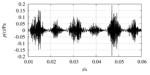
There are two different measures available in this measure group:
Modulation
Absolute \(MOD_{\text{abs}}\)
Relative \(MOD_{\text{rel}}\)
MODabs#
Definition#
The \(MOD_{\text{abs}}\) describes the absolute level of amplitude-modulated noise as generated by turbulent flow in leakages and other semi-random defects:
The modulation envelope peak value is related to the standard reference sound pressure \(p_{0}\) (comparable to SPL).
Relevance for End-of-Line Testing#
This measure is optimal for an absolute assessment of air leakage noise and other modulated noise caused by defective devices. If the amplitude of the modulation envelope is below a permissible limit value the DUT may pass the test because the impact on sound quality is negligible. The limit value may be calculated automatically by measuring good units and using the shift algorithm.
Further remarks#
There is no general threshold of \(MOD_{\text{abs}}\) to indicate a clear defect as the absolute level strongly depends on the DUT and the measurement conditions. A certain noise floor is always present after the demodulation consisting of all kinds of broad-band noise sources during the measurement. Use the \(MOD_{\text{rel}}\) to evaluate the modulation symptom strength.
MODrel#
Definition#
The \(MOD_{\text{rel}}\) is a relative measure derived from the \(MOD_{\text{abs}}\) measure:
The peak value of the (squared) modulation envelope is related to the average broadband floor of the modulation spectrum.
Relevance for End-of-Line Testing#
\(MOD_{\text{rel}}\) describes the modulation symptom strength on a relative scale. The standard value in the optimal case is below 0 dB. If \(MOD_{\text{rel}}\) exceeds this value with a certain tolerance (\(\sim\) 5 dB) significant modulated distortion is present. Thus, this threshold can be used as a universally valid limit for end-of-line testing to indicate e.g. leak noise. In contrast to \(MOD_{\text{abs}}\) it neglects the absolute amplitude of the distortion (which may be dominated by uniform noise), audibility and the impact on sound quality.
Further Remarks#
The \(MOD_{\text{rel}}\) supplements the \(MOD_{\text{abs}}\) because it characterizes the modulation symptoms relative to the modulated distortion signal floor. Thus, it represents modulated distortion qualitatively (comparable to modulation index of AM). Only values clearly above 0 dB indicate significant symptoms (values below are not indicated).
Deterministic Distortion#
This measure group represents any kind (high-order) harmonic distortion (HOHD) generated by reproducible and periodic defect symptoms.
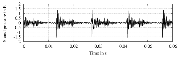
There are two subgroups available representing driver defects and respectively leak distortion:
Deterministic
Absolute \(DET_{\text{abs}}\)
Relative \(DET_{\text{rel}}\)
Deterministic (Leak)
Absolute \(DET(L)_{\text{abs}}\)
Relative \(DET(L)_{\text{rel}}\)
DETabs#
Definition#
The \(DET_{\text{abs}}\) is an absolute measure for deterministic (strictly periodic) Rub&Buzz distortion. Based on long-term spectral analysis it evaluates the averaged high order harmonic distortion. The distortion peak value (using phase and amplitude in time domain) is expressed as a sound pressure level:
Relevance for End-of-Line Testing#
The \(DET_{\text{abs}}\) only considers deterministic distortion, which is caused for example by hard limiting of the voice coil movement or parasitic oscillators, like a beating connection wire. Most rub and buzz defects have a strong deterministic component. If the \(DET_{\text{abs}}\) value exceeds a predefined limit the deterministic distortion has a strong impact on sound quality and the device fails the test.
DETrel#
Definition#
The \(DET_{\text{rel}}\) is derived from \(DET_{\text{abs}}\) as a relative level measure representing the crest factor of deterministic distortion. It is calculated by relating the distortion peak to the distortion RMS value:
Relevance for End-of-Line Testing#
The \(DET_{\text{rel}}\) describes the impulsiveness of deterministic distortion. Noise and regular distortion in loudspeakers are not impulsive and have a \(DET_{\text{rel}} <\) 12 dB. This threshold can be used as a universally valid limit for end-of-line testing but neglects the absolute amplitude of the distortion, audibility and the impact on sound quality.
DET(L)abs#
Definition#
The \(DET(L)_{\text{abs}}\) is an absolute measure for specific deterministic distortion caused by air leaks and is based on averaged long-term spectral analysis. The peak value of the averaged leak distortion is expressed as an SPL:
Relevance for End-of-Line Testing#
The \(DET(L)_{\text{abs}}\) only considers deterministic distortion which is very specific for small air leaks which emit no or only little (modulated) turbulent flow noise, especially at low stimulus levels. Thus, it is a very sensitive and independent measure. Combined with the \(MOD_{\text{abs}}\) measure it is very powerful for detecting leaks by covering all possibly symptoms of leak noise.
DET(L)rel#
Definition#
The \(DET(L)_{\text{rel}}\) is derived from \(DET(L)_{\text{abs}}\) as a relative level measure. It represents the (modified) crest factor of deterministic leak distortion using a cleaned RMS value:
Relevance for End-of-Line Testing#
The \(DET(L)_{\text{rel}}\) describes the impulsiveness of deterministic leak distortion. Noise and regular distortion in loudspeakers are not impulsive and have a \(DET(L)_{\text{rel}} <\) 12 dB. This threshold can be used as a universally valid limit for end-of-line testing. In contrast to \(DET(L)_{\text{abs}}\) it neglects the absolute amplitude of the distortion, audibility and the impact on sound quality.
Random Distortion#
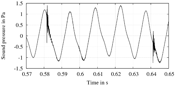
This measure represents strictly non-harmonic distortion in the time domain. As no averaging is applied the full phase information is used to detect even tiniest impulses caused by randomly occurring defects like loose particles.
Definition#
Random is an absolute measure for randomly occurring distortion. It represents the instantaneous peak value of the non-deterministic sound pressure response as an SPL:
The non-deterministic signal is obtained by removing the deterministic distortion components (fundamental and harmonic distortion).
Relevance for End-of-Line Testing#
Random describes the peak value of the distortion signal in the time domain exploiting phase and amplitude information. This measure is very sensitive for loose particles producing random symptoms.
Note
The Random distortion result is available only in the separate ALD task. In the SPL task the Rub&Buzz measure detects random distortion.
