
KCS-ID – Parameter Identification#
Introduction#
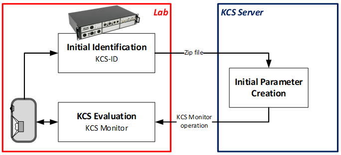
The KCS-ID Parameter Identification is a measurement module which is required for creating initial speaker parameters for the KLIPPEL Controlled Sound Technology (KCS). The KCS-ID uses a multi-tone stimulus to excite a loudspeaker and measures electrical voltage, current and optionally laser and microphone signals. After the measurement, the signals recorded by KCS-ID are sent to the KCS Server which automatically creates initial KCS data comprising linear and nonlinear speaker parameters for the particular KCS hardware platform. This initial data set is stored in a KCS Monitor operation that can be downloaded from the server. The KCS Monitor operation can connect to any supported KCS hardware platform and a KCS control session can be started.
This manual gives step-by-step instructions on how to create the initial data:
Hardware Setup
Performing a measurement
Creating initial data
System Requirements#
The following hardware is required for running KCS-ID:
KLIPPEL Analyzer 3 (KA3)
Power amplifier or KLIPPEL AMP Card
It is highly recommended to use
Microphone
Triangulation Laser
The following software is required for running KCS-ID:
An installation of KLIPPEL dB-Lab of version >= 212.332
KCS-ID license
Internet access is required for creating initial parameters on the KCS Server.
Hardware Setup#
Hardware Connection#
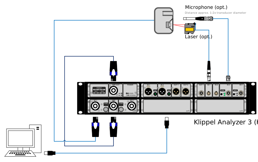
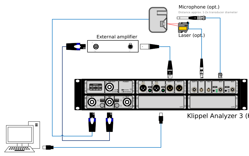
The hardware setups on the KLIPPEL KA3 comprising one Speaker Card, one Laser CARD, one XLR Card and an optional AMP Card is illustrated in the figures underneath. For more information about the hardware, please see the hardware manual.
Laser and microphone sensors are not necessarily required for operating KCS-ID and KCS Monitor. However, these sensors are highly recommended for determining the voice coil’s peak displacement automatically and for getting a comprehensive set of diagnostics information.
The microphone should be placed in the near-field of the device under test to achieve a high signal-to-noise ratio. A microphone calibration is not necessary as a relative measurement comprises all relevant information required by KCS-ID. Make sure that IEPE/phantom power is switched on using the buttons next to the microphone input on the KA3’s front panel.
If a transducer with multiple voice coils shall be used, please see the modified hardware configuration here.
Warning
Keep the polarity consistent. It is crucial that the speaker is connected to the KA3 with the same polarity as later on the KCS target hardware platform. A positive DC voltage should move the voice coil outwards (away from the back plate).
Hardware Setup - Routing#
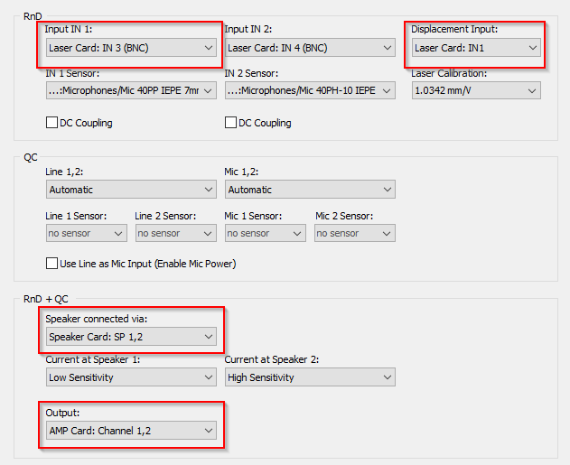
In the dB-Lab software’s tool bar, open the KA3 Signal Configuration  to setup the
routing. Set the correct output channel (AMP if an AMP card is used or XLR if an external
amplifier is used) and input channels for the optional external sensors.
to setup the
routing. Set the correct output channel (AMP if an AMP card is used or XLR if an external
amplifier is used) and input channels for the optional external sensors.
If not done already, calibrate your laser.
Note
The current sense (Low/High Sense) is set dynamically by the KCS-ID operation and does not have to be changed for the measurement.
Performing Measurements#
Basic Measurement Setup#
Open a database by pressing  Select Database in the dB-Lab software. Create
  a new
KCS-ID operation, open its Properties by right-clicking on the operation and set up the
measurement as follows. It is assumed that the hardware is set up as described in the previous
section and laser sensor and microphone are connected to the KA3.
a new
KCS-ID operation, open its Properties by right-clicking on the operation and set up the
measurement as follows. It is assumed that the hardware is set up as described in the previous
section and laser sensor and microphone are connected to the KA3.
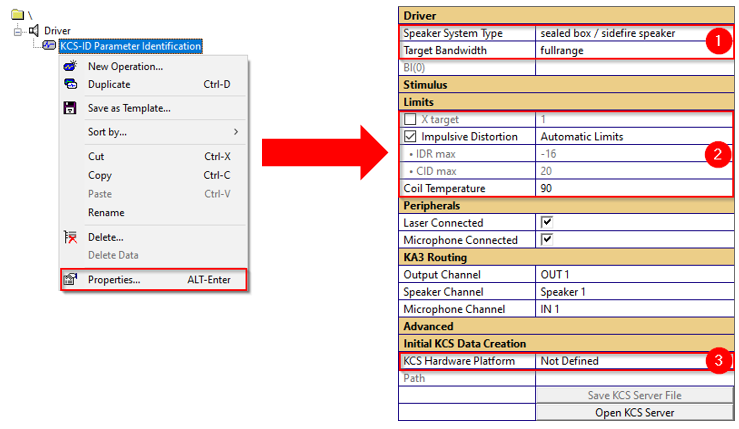
Select the Speaker System Type (free air, sealed box or vented box/passive radiator) and the Target Bandwidth (fullrange, woofer/midrange or subwoofer).
Warning
The KCS-ID measurement has to be performed in an enclosure of similar specification (same volume and same port/passive radiator) as will be used in the KCS on-line mode.
Select Limit Parameters. It is recommended to never switch off the Impulsive Distortion limit which indicates excessive impulsive distortion (Rub&Buzz). If the target displacement xtarget is known, it should be specified here as limit parameter. See the next section for more detailed information about the limit parameters.
Select the hardware platform the initial data shall be created for. Only KA3: Also, the Target amplifier (AMP card or External amp) has to be specified. If External amp is selected, the same amplifier with the same gain settings on which the KCS-ID measurement is performed has to be used as amplifier for running KCS.
This step can also be done after the measurement.
Note
KA3 target platform only: It is highly recommended to use the AMP card for KCS evaluation if its voltage and power capabilities are sufficient for the particular speaker, because DC coupling is not supported on external amplifiers. The AMP card can provide a peak voltage of approx. 20 V and can handle a minimum load of 2 Ω (see specification [H6 Amplifier Card])
Note
Bl(0) can only be imported if no laser is used (switch off Laser Connected in the Peripherals category). If a laser is used (which is highly recommended), Bl(0) is identified accurately on the KCS Server.
Additional Options#
Stimulus#
The Stimulus settings are set to Automatic by default. You can select a higher Start Voltage if you use a big speaker and want to accelerate the ENLARGEMENT MODE. In some cases, the Level might be set to Manual to fine-tune xmax (see How to achieve a higher xmax?)
Peripherals#
Select whether laser/microphone sensors are used in this measurement. It is recommended to use both, however sometimes the laser might not have access to the transducer’s membrane and cannot be used. Note that a microphone calibration is not required for this measurement.
Advanced#
Save Intermediate Results saves the results of each measurement block into a new KCS Monitor operation. It is not recommended to activate this option. However, KLIPPEL support might require this data in case of problems.
Limit Parameters#
In the ENLARGEMENT MODE, the excitation voltage is incrementally increased until the first limit parameter is reached or exceeded. Following limit parameters are available:
X target - Maximum absolute peak voice coil excursion that shall be used in the target application. If a laser is used, the peak displacement value is measured by a laser sensor. If no laser is used, it is calculated by a linear speaker model and a Bl(x=0) import which e.g. can be taken from the driver’s datasheet. Note that in this case, the displacement value can differ significantly from the real voice coil excursion as it depends on a manual Bl(x=0) import and only uses a linear speaker model. See xmax and xtarget for further information about xtarget and xmax.
Impulsive Distortion - Impulsive distortion is identified by exploiting out-of-band distortion in the sound pressure signal. Two parameters indicating excessive impulsive distortion/Rub&Buzz issues are used: The IDRMT (Impulsive Distortion Ratio according to IEC 60268-21 for multi-tone stimuli) limit is the ratio between peak higher order distortion and mean SPL. To be sensitive to very audible short impulsive distortion peaks with low energy (such as beating wires), the crest factor CIDMT of the out-of-band distortion is calculated. High IDRMT or CIDMT values indicate that the speaker is working above its safe working range.
The impulsive distortion metrics IDRMT and CIDMT are calculated similarly like the IDR or CID values for sinusoidal excitation (see TRF Transfer Function module). However, the crest factor of the multi-tone is much higher than that of the sinusoidal tone, which is one reason why the multi-tone impulsive distortion limits are much lower than their counterparts for sinusoidal excitation. It is not recommended to change the default impulsive distortion limits.
Note
The IDR is very susceptible for impulsive distortion (e.g. voice coil rubbing) and not so much for air flow noises which exhibit less impulsive characteristics.
Coil Temperature – Maximum allowed relative voice coil temperature increase. If this limit is exceeded, the measurement is immediately stopped. The measurement of the coil temperature is done by measuring its DC resistance. The reference temperature is measured in the LINEAR MODE.
Note
Voice coils do not heat up homogenously. Usually, the hottest place is at the rims, while it is colder in the gap. KCS-ID measures the average temperature, hence allow some margin to the maximum absolute maximum temperature rating of the voice coil.
Measurement preparation#
Before starting the measurement, check the following:
Microphone: If you are using a microphone requiring IEPE voltage supply, make sure that IEPE is activated for the respective channel on the KA3 (button and green light on the front plate of the laser card). Adjust the microphone in the nearfield of the speaker. Make sure that the microphone is capable of measuring the occurring maximum SPL without clipping.
Laser: Use a sensor with sufficient maximum displacement range and good SNR. Make sure that the relative position of laser and the DUT housing does not change during the measurement. Adjust the laser to the membrane. Check that the sensor is within its allowable range. Apply a white dot of paint or chalk to the diaphragm at the position where the laser beam is pointing. This drastically improves the SNR for diaphragms with dark color.
If the impulsive distortion limit is activated: Avoid any impulsive noise sources apart from the DUT, which can affect the impulsive distortion measurement. Otherwise, the identified allowable maximum excursion xmax might not be identified correctly. Consider countermeasures like:
Transducer: Avoid that the DUT is rattling due to inappropriate placement. Small transducers can be rested on a piece of soft foam or immobilized with clay during the measurement. Larger transducers should be clamped in a good stand that does not rattle when exposed to vibration from the DUT.
Measurement environment: At high amplitudes and inertia forces, the DUT might cause vibration and hence rattling to adjacent objects (typical examples: rattling keys on the office desk or feet of mobile microphone stands that start “jumping”). Be sure to remove these before triggering the measurement.
Running and Interpreting Measurements#
Warning
High sound levels and laser radiation occur during the measurement! Ensure that no living creature including yourself can suffer harm. Use appropriate shielding or protection gear.
Press Run in dB-Lab’s tool bar to perform a measurement.

Now multiple measurement steps are performed consecutively:
LINEAR MODE: Small signal parameters are identified and optimum settings for the NONLINEAR MODE are determined.
ENLARGEMENT MODE: The excitation level is incrementally increased to approach the voice coil’s peak displacement xmax. This mode is finished when any of the limit parameters are reached.
NONLINEAR MODE: This measurement excites the speaker so that the peak voice coil displacement corresponds approximately to its working range xmax in the final application.
THERMAL MODE: If the voice coil heating was not sufficient in the NONLINEAR MODE, another measurement of the voice coil heating characteristic is performed before measuring the cooling curve.
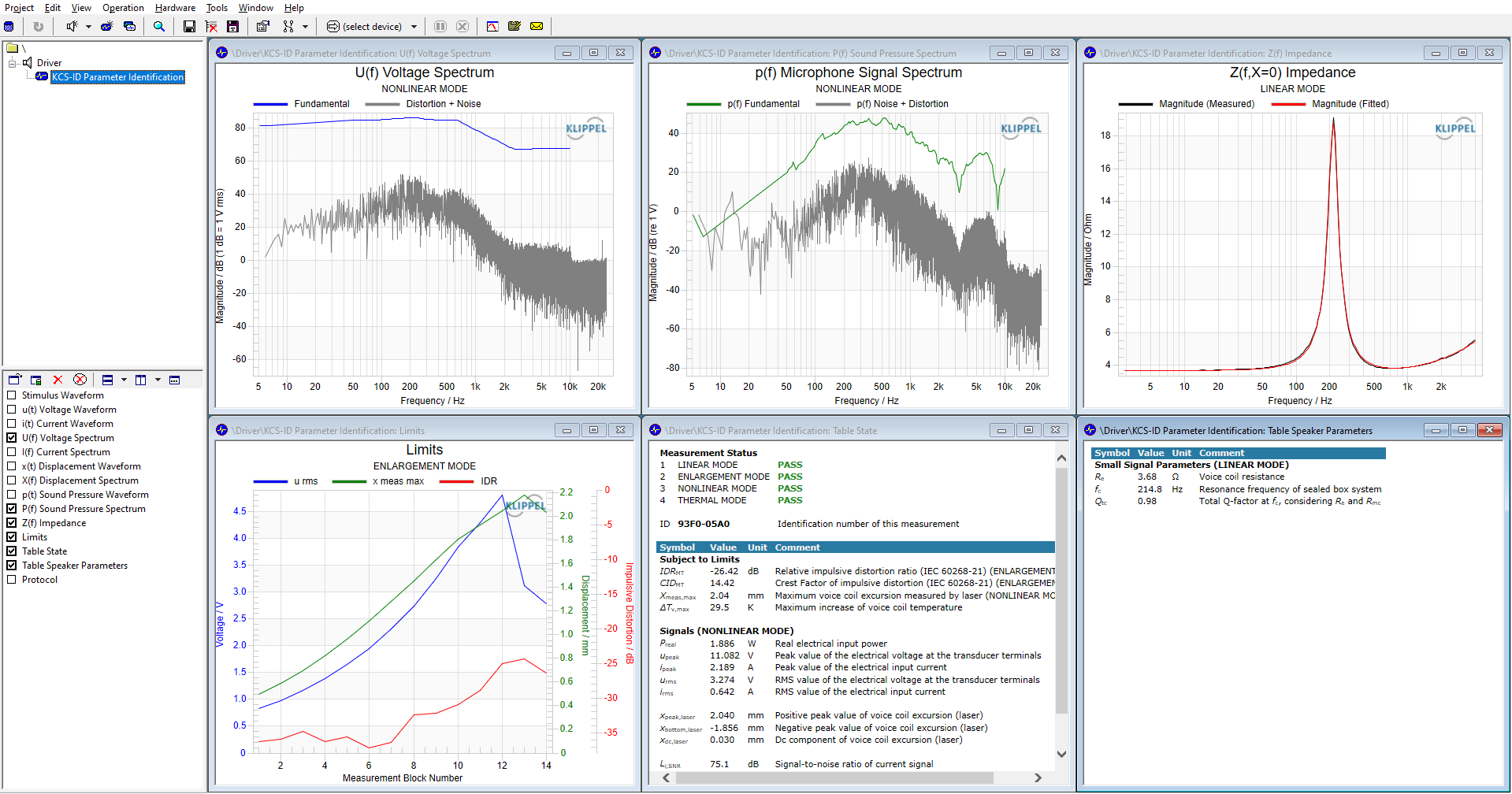
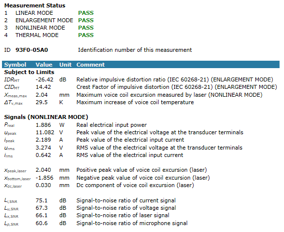
If the measurement has successfully finished, the measurement status overview in the State table displays a PASS after all measurement modes and an 8-character identification number. Initial KCS data can now be created based on this measurement. If the measurement has not finished successfully, check the Speaker Parameters window for any warning messages and follow its instructions.
Creating Initial Data#

The KCS-ID measurement data has to be sent to the KCS Server so that initial data can be created for your specific KCS Hardware Platform. Save the zip file on your hard drive. Now press Open KCS Server which opens KCS Server website www.klippel-hub.de.
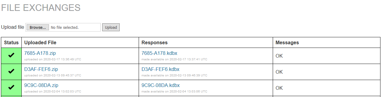
After logging-in, the zip file can be uploaded. Based on this data, the KCS Server creates a full initial data set for operating KCS comprising linear and nonlinear speaker parameters, calibration values and more. After the processing is finished, a KCS Monitor operation is created and can be downloaded.
Now you are ready to start KCS on-line processing. Before evaluating KCS, it is highly recommended to see the KCS Monitor manual, especially the sections Tutorial 4 – Alignment and Equalization and Tutorial 5 – Protection and Limiter which describe steps how to achieve best audio performance.
Note
The hardware platform can be selected after the KCS-ID measurement has finished. If initial data for different target platforms shall be created, it is not necessary to perform another KCS-ID measurement.
Note
Request a KCS-Server account by contacting KLIPPEL support. Note that this login is not connected to the Download Manager log-in on www.klippel.de/dm.
xmax and xtarget#
Why is xmax not equal to xtarget?#
A maximum voice coil displacement xmax is automatically detected in the KCS-ID and on the KCS Server. xmax is the voice coil excursion which shall never be exceeded during KCS on-line operation. The determination of xmax is based on the KCS-ID limit parameters
X target
Impulsive distortion
If one of these limits is reached in the ENLARGEMENT MODE, the corresponding voltage is used to perform the NONLINEAR MODE measurement which is the basis for nonlinear parameter identification.
It can happen that the resulting xmax which the KCS Server determines is lower than the xtarget, even if it was reached in the KCS-ID measurement. This can have multiple reasons:
No Laser in KCS-ID#
If no laser is used in in the KCS-ID measurement, the peak excursion is estimated based on a linear speaker model using a manual Bl(0) import. However, a linear model cannot describe a real speaker with good accuracy. Based on the degree of nonlinearity of the speaker, the peak excursion estimation can be quite significantly lower than in reality. Hence, when the speaker’s nonlinear parameters are identified on the KCS Server, the resulting excursion might be lower than the estimation of the KCS-ID.
Asymmetric Voice Coil Excursion#
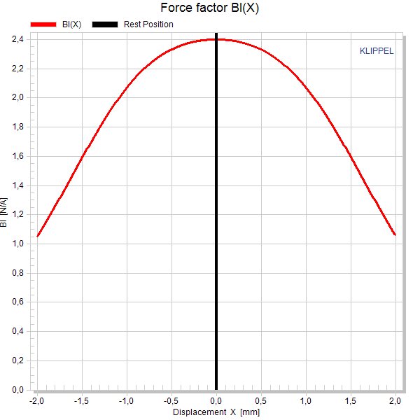
Electrodynamic transducers are nonlinear systems. Based on the particular design, some nonlinearities might exhibit a significant asymmetry which can cause an asymmetric peak excursion. The positive peak displacement can for example be higher than the absolute peak value on the negative side (see curves below).
If the voice coil is never reaching a certain excursion range during the KCS-ID measurement, the parameter identification system running on the KCS Server cannot identify the speaker parameters in this range reliably. In addition it is not known whether impulsive distortion occurs if the voice coil would be driven to this excursion range during KCS on-line operation with other signals.
Hence, the KCS Server determines a safe and conservative xmax value, whereas the peak excursion displayed in the KCS-ID is an absolute peak value.
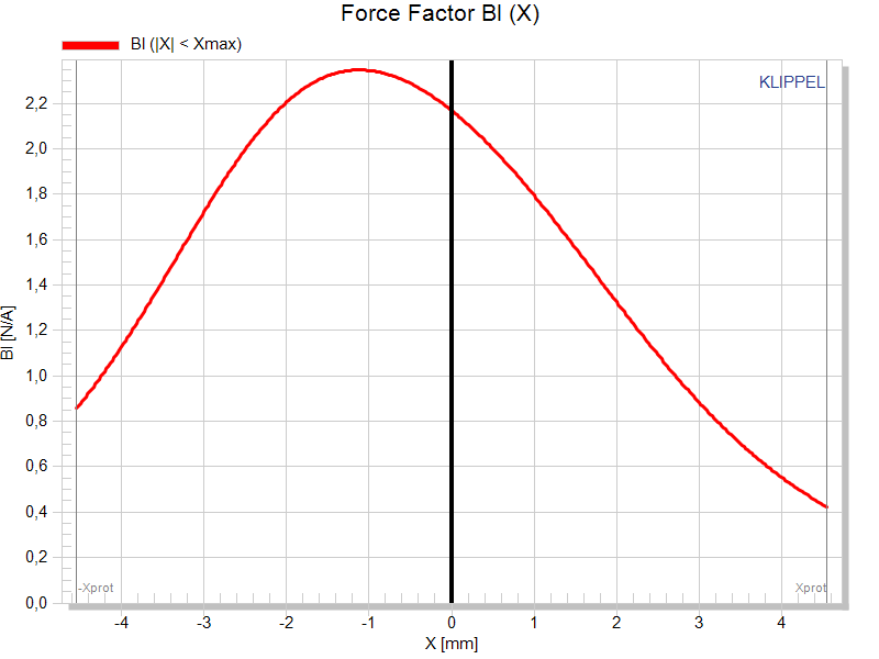
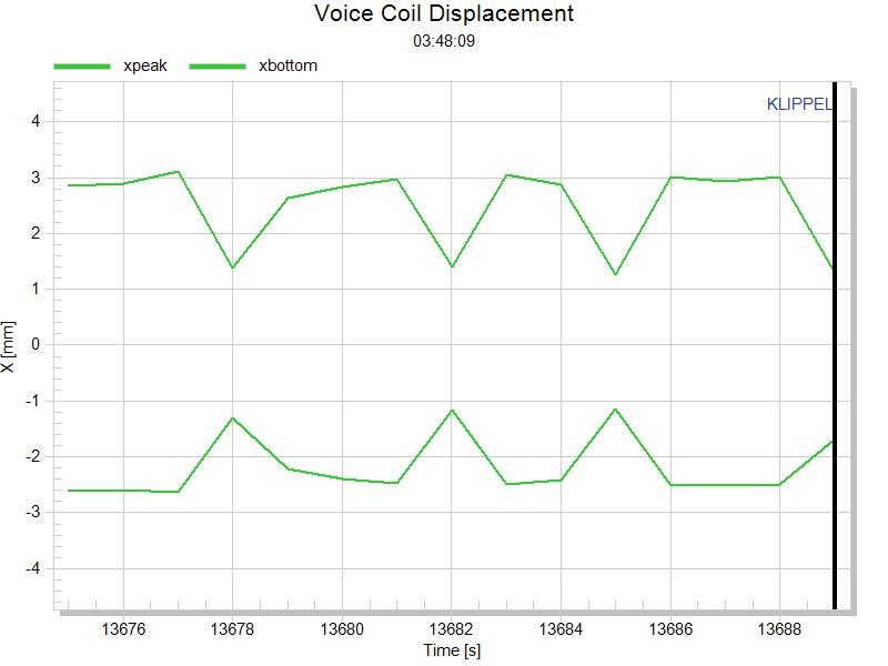
Nonlinear Parameters can cause asymmetric peak excursion in the KCS-ID measurement
Significant Voice Coil Heating during KCS-ID#
If the voice coil heated up significantly during the NONLINEAR MODE, the excursion can decrease during the measurement due to an increasing voice coil resistance. Hence the peak excursion was overestimated in the shorter ENLARGEMENT MODE measurement.
How to achieve a higher xmax?#
If you are sure that the transducer can handle a higher xmax than determined by the KCS Server, you can proceed in two ways. To continue using the automatic mode for determining stimulus level, review the limit settings (see Limit Parameters) along with the measurement conditions (see Measurement preparation). Alternatively, you can manually force the KCS-ID measurement to apply a higher excitation voltage. The easiest way to do that is
Open the KCS-ID operation which lead to an insufficient xmax and copy the operation.
In the KCS-ID Properties (category Stimulus), change the Level from Automatic to Manual

Increase the level depending on how much you want to increase the xmax compared to the previous measurement.

Repeat the measurement and create initial data with higher xmax using the KCS Server again.
Transducers with multiple voice coils#
Initial KCS data can also be generated for transducers with multiple voice coils, each driven by a separate amplifier channel. Connecting the voice coils in parallel increases the driver’s voltage sensitivity. As a result, less voltage is required to achieve the same SPL than with a series connection. This can be advantageous in applications with limited amplifier supply voltage, such as automotive audio systems.
The table below compares the parameters, voltage sensitivity, efficiency, and electrical requirements for parallel and series voice-coil connections. Compared to a series connection, a parallel connection provides N times higher voltage sensitivity (where N is the number of voice coils). The voltage required to achieve the same sound pressure level (SPL) is therefore reduced by a factor of N, while the required current increases by the same factor. The efficiency, resonance frequencies, and Q-factors remain unchanged.
\(Bl\) |
\(K_\text{ms}\) |
\(M_\text{ms}\) |
\(L_\text{e}\) |
\(R_\text{e}\) |
Sensitivity |
Motor Efficiency |
|
|---|---|---|---|---|---|---|---|
Single Coil |
1 |
1 |
1 |
1 |
1 |
1 |
1 |
Parallel |
1 |
1 |
1 |
1/2 |
1/2 |
2 |
2 |
Series |
2 |
1 |
1 |
4 |
2 |
1 |
2 |
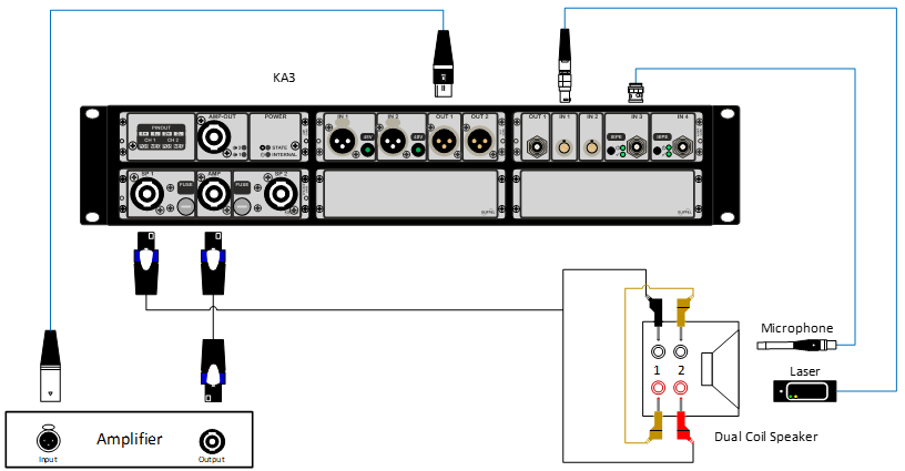
To generate the initial KCS data, perform the KCS-ID operation with the voice coils connected in series, as shown below for a dual voice-coil loudspeaker.
Because the voice coils are connected in series, the amplifier must provide a proportionally higher peak voltage during the KCS-ID measurement. The required peak voltage increases approximately in proportion to the number of voice coils. Ensure that your amplifier is capable of delivering the required peak voltage.
Note
KCS only supports multi coil configurations if all coils show identical small and large signal properties. Please contact Klippel if you are unsure if your transducer is suited.
Troubleshooting#
KCS-ID messages#
Amplifier Headroom exceeded#
The KA3’s amplifier can provide approx. 19…22 V peak (depending on connected the DC resistance). The error message pops up if more voltage is required to reach a certain limit or the excitation voltage is set manually to a level exceeding the amplifier’s capability. Note that the multi-tone stimulus has a crest factor of approx. 3. Hence, the maximum possible voltage is 6…7 V RMS when the internal AMP card is used.
You can use an external amplifier that can provide more voltage to drive the transducer to its limits or to reach a higher excitation voltage.
If 6…7 V RMS are sufficient because the target amplifier used in the KCS online mode cannot deliver more voltage anyway, you can set the level manually to approx. 6 V RMS on the KCS-ID’s property page’s category Stimulus.

High voice coil position change detected#
This message indicates that between LINEAR MODE and NONLINEAR MODE either
the voice coil was shifted significantly due to very asymmetric nonlinear behavior of the transducer or
the distance between laser sensor and transducer membrane position has changed.
Note that the rest position of the NONLINEAR MODE is used as reference rest position used in the KCS on-line mode. The voice coil stabilization feature will shift the voice coil to this reference rest position.
Check correct Speaker System Type setting#
The KCS-ID measurement performs a small signal speaker parameter identification in the LINEAR MODE. If it detects that e.g. the number of distinct impedance magnitude peaks does not correspond to the specified Speaker System Type (e.g. sealed or vented enclosure), this message appears.
Note
In rare cases, the warning might trigger even if the correct speaker type is set. In this case you do not have to do anything.
KCS Server messages#
The KCS Server website might display warnings and information after a KCS-ID file has been uploaded. See explanations of selected info and error messages below.
Info/Warning Messages#
Low both-sided Bl(x) decay. Detection of the voice coil rest position and stabilization might not work optimally.#
For identifying the voice coil rest position, KCS evaluates the nonlinear distortion found in the measured current signal caused by the nonlinear Bl(x) speaker characteristic. If the Bl(x) curve is too linear, not enough distortion is created to perform an identification of the rest position. In this case also an active shifting of the voice coil position using a DC voltage (Stabilization) is not possible.
Note that KCS will work anyway, but higher safety margins for the maximum allowed excursion are required, leading to less acoustical output at low frequencies.
For KCS it is highly recommended to use a speaker with a higher decay of the Bl(x) curve (usually a decay to 50…75 % relative to Bl(x=0). The higher Bl(x) decay leads to higher efficiency and sensitivity and the added nonlinear distortion caused by the more nonlinear Bl(x) is compensated by KCS. In addition, the KCS stabilization allows to exploit the working range of the speaker optimally.
Bl(x) offset > 25%. Use a transducer with centered voice coil offset for maximizing efficiency.#
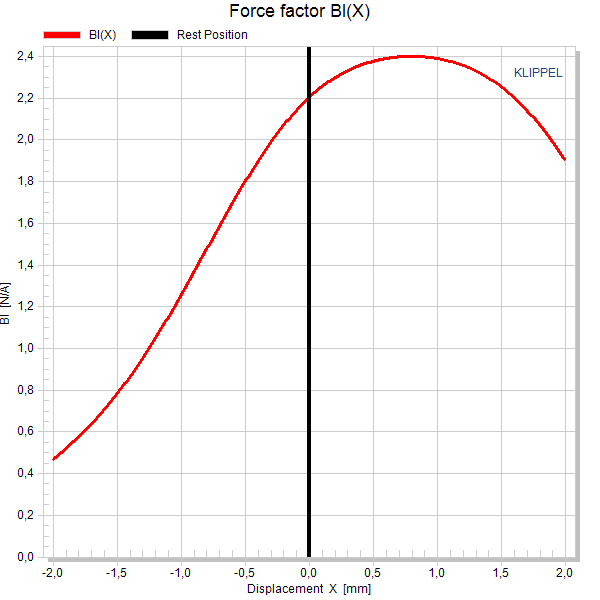
If the voice coil offset is very high compared to the peak displacement (first picture), sensitivity and efficiency drop. For best performance it is recommended to use a transducer with a centered voice coil (second picture).
Xmax had to be reduced. It could not be realized on both positive and negative side of the identified Bl(x) curve.#
See xmax and xtarget.
Xmax was reduced due to exceeded IDR limit.#
xtarget could not be reached because the impulsive distortion limit (IDR Limit) was hit at excursions smaller than xtarget. Either the transducer cannot be used up to the specified peak excursion without producing excessive distortion or the IDR Limit was set too conservatively.
Laser Position has changed by more than 20 % of maximum measured excursion during KCS-ID measurement.#
Amplifier Gain is not sufficient to reach desired Xmax. Xmax has been reduced.#
The gain of the specified target amplifier is not sufficient to drive the speaker to the xmax determined in the KCS-ID. xmax was reduced.
Error Messages#
High Linear Identification error/High Nonlinear Identification error#
The speaker parameters could not be identified with sufficient accuracy. Check if the Speaker System Type was specified correctly on the property page of the KCS-ID operation. If it was, you might contact KLIPPEL support.
Bl(x) variation too high. Reduce limits or excitation level.#
If the Bl(x) curve decays to a value smaller than 0.25*Bl(x=0) at either positive or negative displacements, highest accuracy of the nonlinear parameters cannot be ensured under all circumstances. In addition, a disproportionate high peak voltage is required in KCS on-line mode for linearization. Reduce limits in the KCS-ID or reduce the voltage manually.
Kms(x) variation too high. Reduce limits or excitation level.#
If Cms(x) = 1/ Kms(x) decays to a value smaller than 0.25*Cms(x=0) at either positive or negative displacements, highest accuracy of the nonlinear parameters cannot be ensured under all circumstances. In addition, a disproportionate high peak voltage is required in KCS on-line mode for linearization. Reduce limits in the KCS-ID or reduce the voltage manually.
